Week 9 - Attachment Feature Creation - Challenge 1
RIB DESIGN
DRAFT ANALYSIS
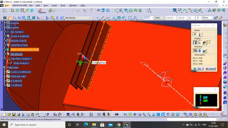
FIG 1.0
The above image(FIG 1.0) shows the draft analysis of RIB 3 with a draft angle of 0.5 degrees.According to design rules the rib draft is 0.5 degree maximum.
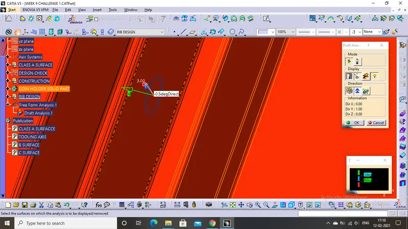
FIG 1.1
The above image(FIG 1.1) shows the draft analysis of RIB 2 with a draft angle of 0.5 degrees.According to design rules the rib draft is 0.5 degree maximum.
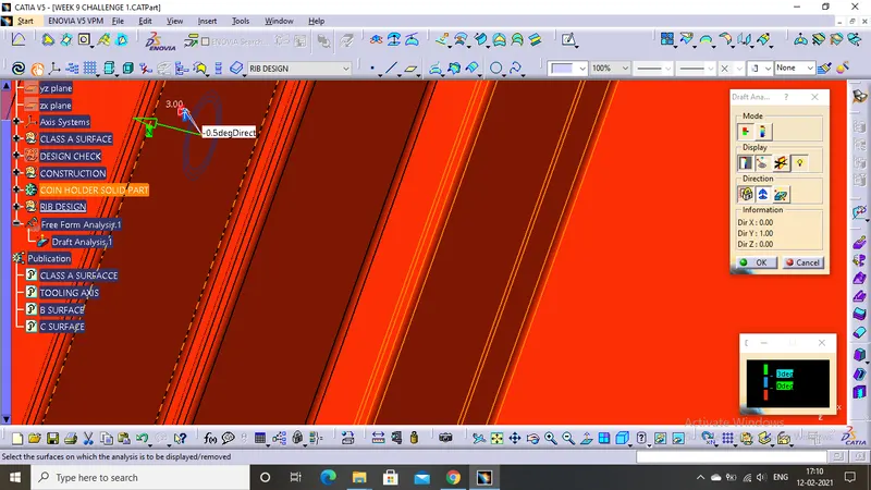
FIG 1.2
The above image(FIG 1.2) shows the draft analysis of RIB 1 with a draft angle of 0.5 degrees.According to design rules the rib draft is 0.5 degree maximum.
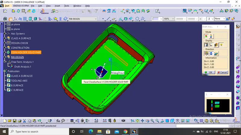
FIG 1.3
The above image (FIG 1.3) shows the draft analysis of the HOLDER BASE with an draft angle of 90 degree.Which clears the 3 degree nominal draft angle and rough patch draft angle of 7 degree.Hence the part is good to go for manufacturing.
*****************************************************************************************************************************************************
RIB DESIGN RULES
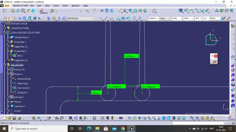
FIG 2.0
FORMULA FOR SPACING= HEIGHT/SPACING=3 , WHERE 3:1 is STEEL , 2:1 PREFERRED
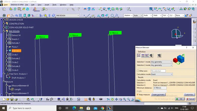
FIG 2.1
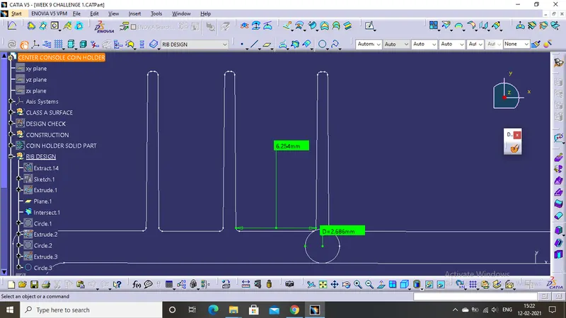
FIG 2.2
RATIO TAKEN AS 2:1
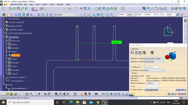
FIG 2.3
*****************************************************************************************************************************************************
TOOLING AXIS
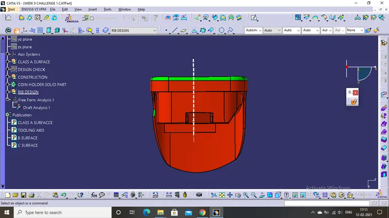
FIG 3.0
The above image(FIG 3.0) shows the TOOLING AXIS in white colour and in this component the draft angle was not available the walls were at 90 degree so the tooling axis is created with the help of point to point command in the lines option.
*****************************************************************************************************************************************************
DIFFERENT VIEWS
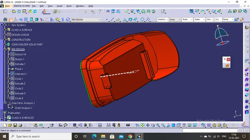
FIG 4.0
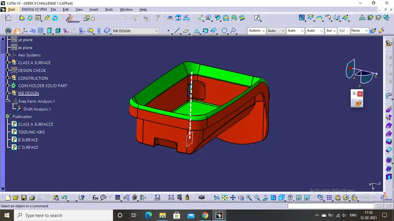
FIG 4.1
FIG 4.2
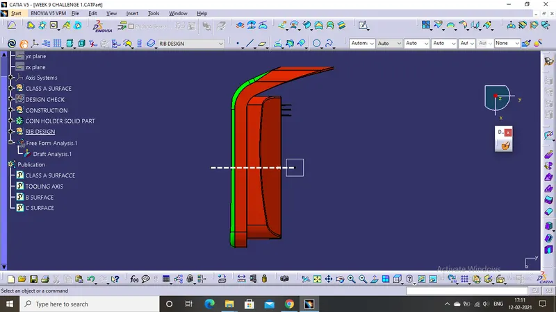
FIG 4.3
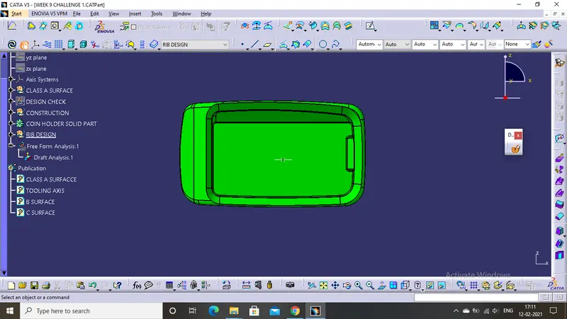
FIG 4.4