Week 9 - Attachment Feature Creation - Challenge 1
NOTE: Draft analysis and the tooling axis creation are explained in the earlier report. In this report, one of the attachment features is explained.
OBJECTIVE:
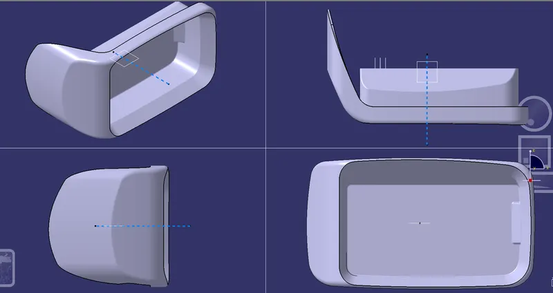
This project intends to create the ribs for the Centre console coin holder.
INTRODUCTION:
- The purpose of modeling ribs to the plastic component is to provide stiffness and strength without increasing the overall wall thickness of the component.
- The attachment feature ribs also make it easier in location and arresting components of an assembly
- It provides alignment in mating parts
- Further also acts as stops or guides for mechanisms
- These attachment features are created on the B side surface of the component
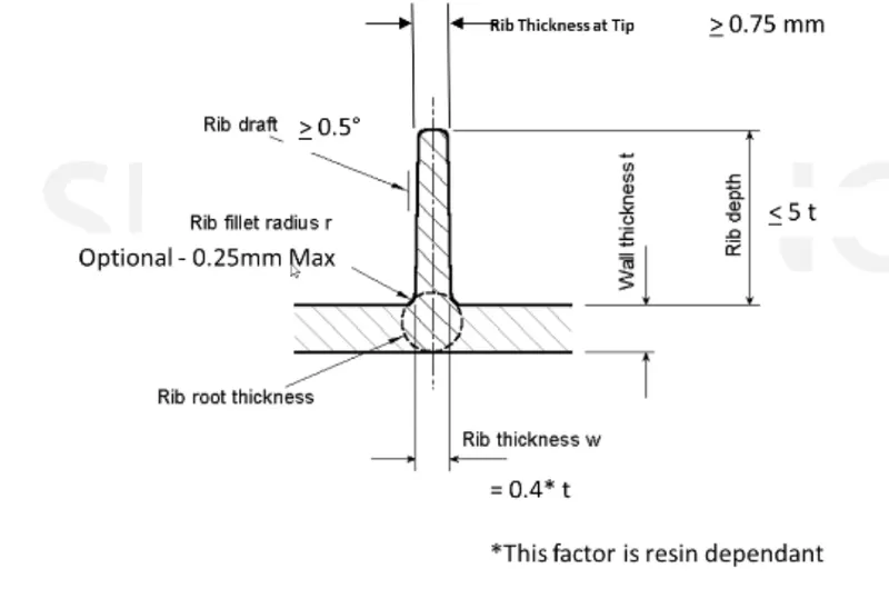
Following are the design rules involved in creating a Ribs on B surface
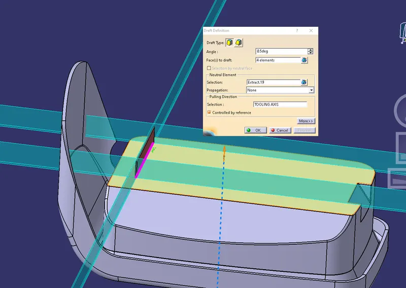
- Draft - We know the draft angle of 3° is ideal for any surfaces in the plastic component. But for the ribs, 0.5° per side is the minimum.
- Wall thickness of the ribs - The wall thickness of the ribs can be 0.4 * wall thickness of the component. If t is the wall thickness of the component, then the wall thickness of the rib is 0.4*t
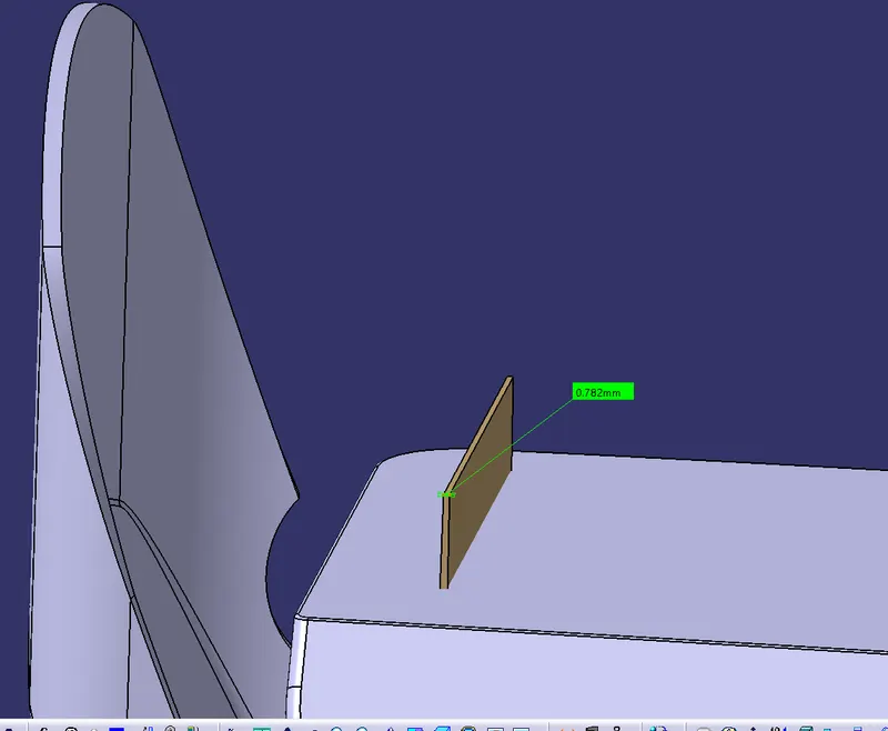
- Minimum wall thickness at Rib tip - The tip of the rib should maintain a minimum wall thickness of 0.75mm. Less than that is not advisable. Because after changing the flow direction of the molten material, it is not easier to reach the very thin area. For ribs, it takes a 90° deviation from the main flow direction.
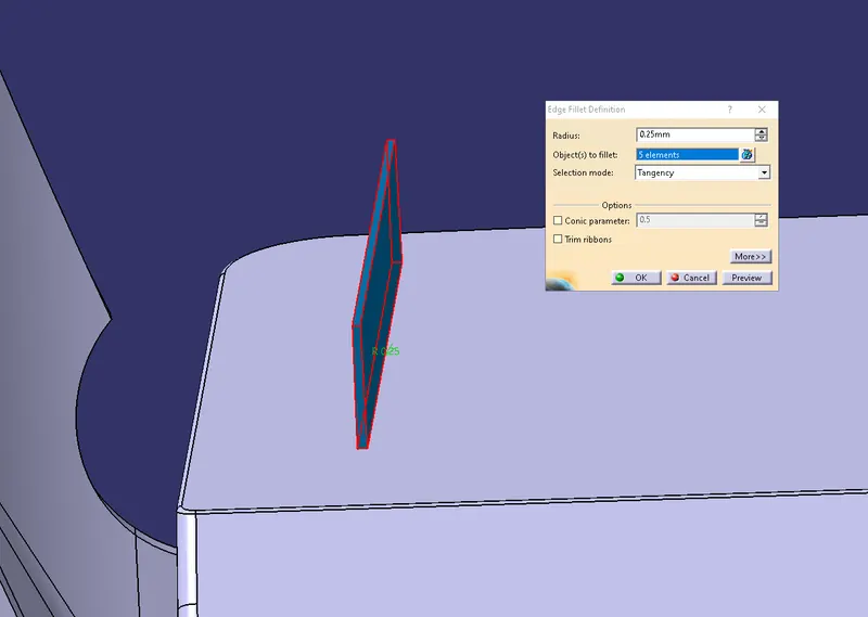
- Rib fillet radius (r) - Optimal rib fillet radius is 0.25mm. But if the component is thicker, we can go until 0.5mm. Above that is not advisable.
- Rib Depth/Height - Rib height must be 5*the component wall thickness
- Spacing b/w ribs - Ribs should be spaced at the H/W ratio when more than one is there. where H is the height of the rib and W is the width b/w ribs. And the accepted ratio is 3:1
- Rib root thickness - The root thickness should not exceed 30% of the component wall thickness
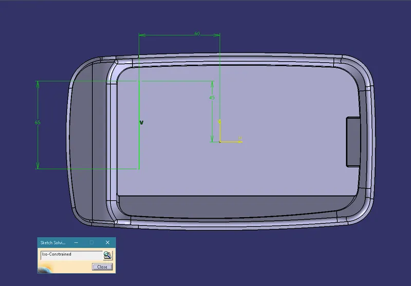
RIB CREATION ON B SURFACE
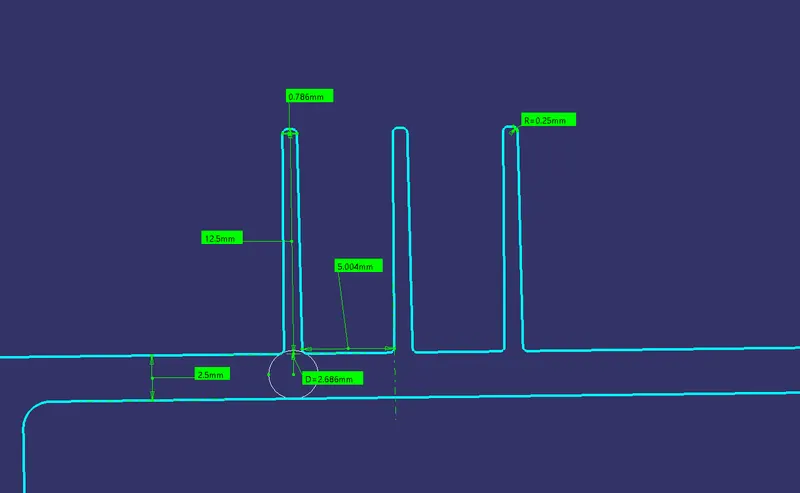
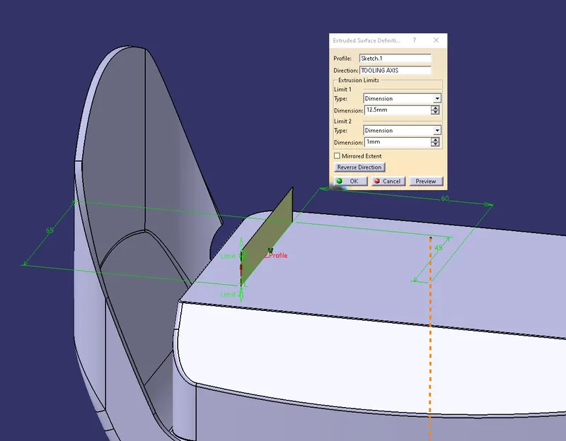
The height of the rib is set according to the above-mentioned rule which is 5*thickness of component = 12.5mm. And the profile is extruded along the tooling direction.
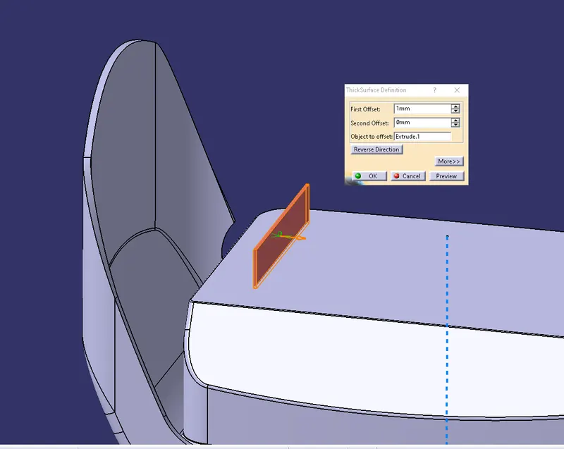
The wall thickness of the rib is given using rule 0.4*t, which gives 0.4*2.5mm = 1mm
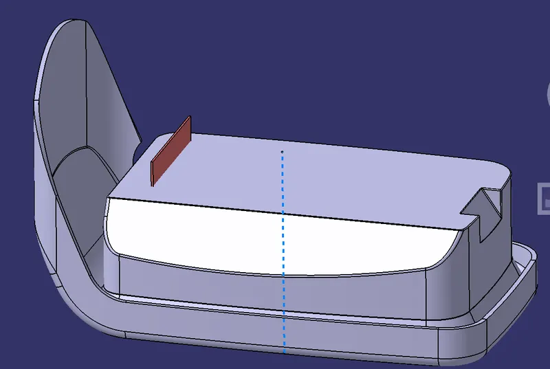
A draft angle of 0.5 degrees on all the faces is given to the rib feature to make it feasible for ejecting.
The rib tip wall thickness is measured after giving the draft angle to make sure whether the minimum thickness is maintained or not. It has a thickness of 0.782mm, which is more than the minimum once.
Here a fillet value of 0.25mm is given to the rib
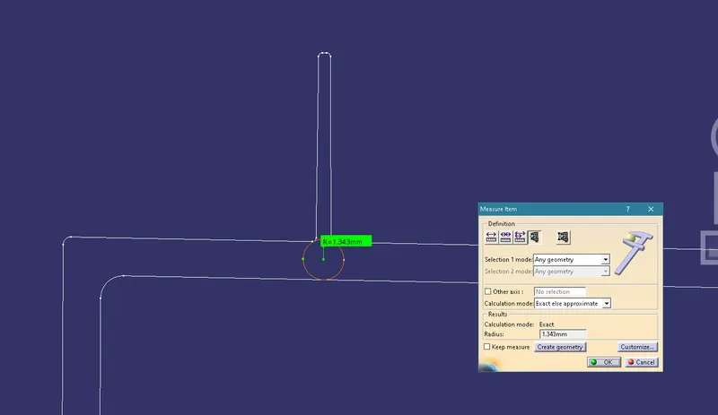
The rib root thickness is also measured to satisfy all the design rules. Which should not be more or less than 30% of the wall thickness. Here the root has a thickness of 2.686mm. Which is not greater than 30%.
Space b/w the ribs
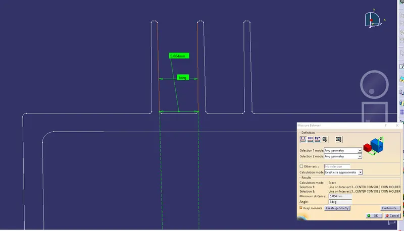
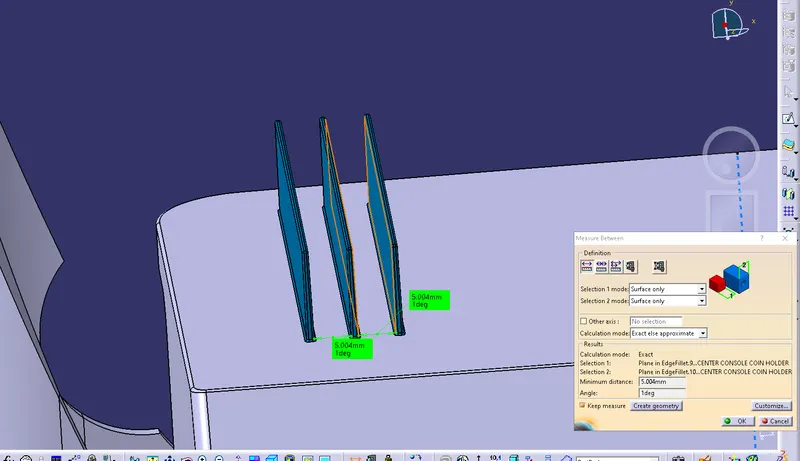
using H/W ration where H is 12.5 and assume W as X.
12.5/X = 3 which give X = 4.16mm. For the safe side the distance b/w the ribs are taken as 5mm.