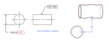
Week 9:- 2D Detailing Challenge
Week 9:- 2D Detailing Challenge
- What are the Drawing templates?
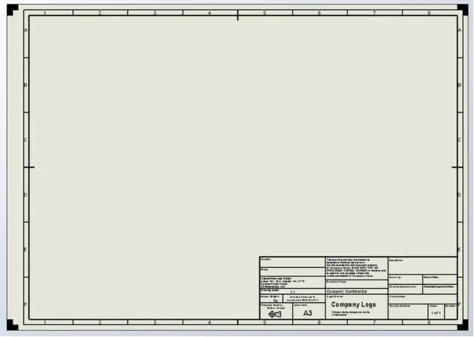
The Drawing sheet with standard information and format is used for all drawings with minor modifications according to the company's requirements. Then the standard sheet is called a drawing template. It consists of quite a lot of information's they are
Company name.
Sheet size.
Scale ratio.
Part name & part number.
Signature or name of the person who drafted the drawing.
Signature or name of the person who checked & approved the drawing.
Material name & properties if required.
They have drawn dates.
Dimension Units.
- What do you understand by 1st& 3rd Angles of projection?
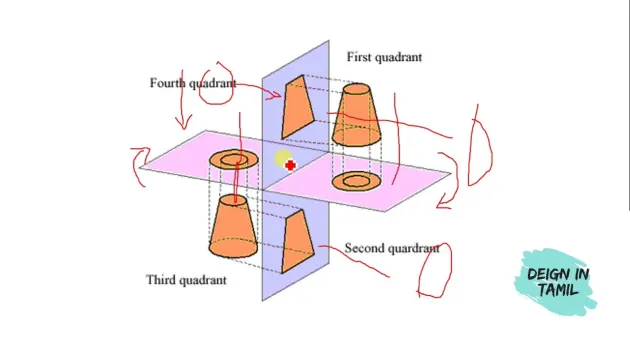
To define an object, technical drawings use 2D views. This is called orthogonal projection. The observer views the projection of the plane. The quadrants should be only rotated in a clockwise direction.
The angles of projection are the view formats for orthogonal views of assemblies or panels. The first and third angles of the arm are majorly used in automotive standards. Understanding the projection angles helps us derive the actual image of a 2D drawing.
The orthographic projection system is used to represent a 3D object in a 2D plane. The orthographic projection system utilizes parallel lines, to project 3D object views onto a 2D plane. According to the rule of orthographic projection. To draw a projection view of a 3D object on a 2D Plane. The horizontal plane is rotated in a clockwise direction.
- What is the First angle & Third angle projection? and why can't we use the 2nd and 4th angle of projection?
The first angle of projection
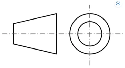
The object lies between the plane & observer.
- The object is placed at the top of the horizontal plane and the front of the vertical plane.
- The first angle projection is widely used in our country and most of the European countries.
- The plane of projection is always taken as solid in the first angle projection.
- The front view is at the top of the horizontal axis.
- Top view at the bottom of the horizontal axis.
- The right view is at the left side of the vertical axis.
The third angle of projection
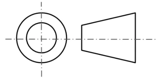
The plane lies between Object & observer.
- The object is placed at the bottom of the horizontal plane and behind the vertical plane.
- Third angle projection majorly opts in the United States.
- The plane of projection is always taken as transparent in the third-angle projection.
- Front view at the bottom of the horizontal axis.
- Top view at the top of the horizontal axis.
- The right view is at the right side of the vertical axis.
- why can't we use the 2nd and 4th angles of projection?
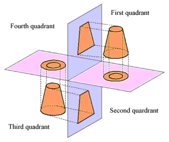
In both the first & fourth quadrants the horizontal plane overlaps with the vertical plane. So we can't get the top and bottom view.
4.What is GD&T? What are the benefits of GD&T?
GD&T is an acronym that stands for Geometric Dimensioning and Tolerancing. It is a symbolic language used by designers to communicate manufacturing constraints and tolerances. This information is conveyed in the form of annotations included in the design of the part.
Benefits of GD&T
GD&T offers the ability to improve quality, decrease cost, and increase speed to market. The GD&T drawing is the continuous thread that connects the design and manufacturing teams and keeps everyone speaking the same language – literally! By engaging the production team during the design, the part functionality can be discussed upfront and the team can jointly develop a manufacturing process that will produce high-precision components - avoiding overly tight tolerances that often drive up cost and result in quality issues during manufacturing. For these reasons, OEMS must partner with an injection molder, such as Crescent Industries, who have Design for Manufacturability (DFM) expertise; this simply means the design and manufacturing teams are integrated to allow manufacturability issues to be identified and addressed during the design process – saving significant time and cost!
Enhanced Communication.
Improved Reliability and Quality.
Increased Flexibility.
It also controls the shape of the part instead of the size.
It can provide bonus tolerance Thereby reducing the rejection Rate.
5. Explain all the symbols used in GD&T?
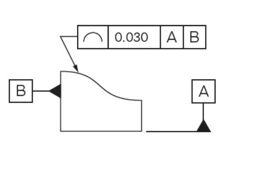
PROFILE OF LINE:
A uniform two-dimensional zone is limited by two parallel zone lines extending along the length of a feature. The amount of deviation that is allowed for a surface to float within a certain dimensional range while maintaining the shape or form of each line element that makes up that surface
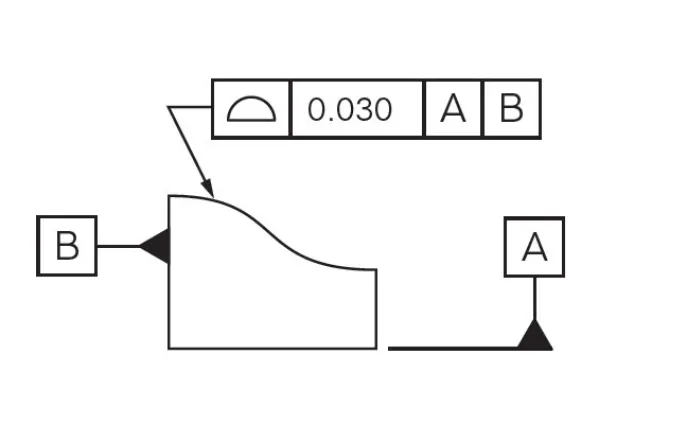
PROFILE OF SURFACE:
It is the amount of deviation that is allowed for a surface. A uniform three-dimensional zone contained between two envelope surfaces separated by the tolerance zone across the entire length of a surface
ANGULARITY:
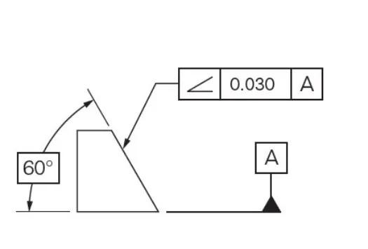
The distance between two parallel planes, inclined at a specific basic angle in which the surface, axis, or center plane of the feature must lie. It requires that all points on a specified feature must form an angle with a datum.
PERPENDICULARITY:
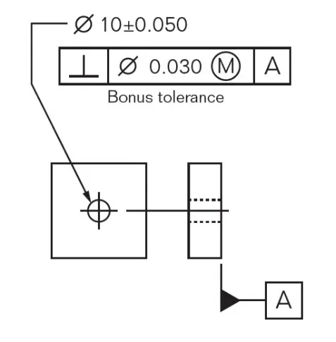
The condition of a surface, axis, median plane, or line which is exactly at 90 degrees with respect to a datum plane or axis. It requires that all points on a specified feature must be perpendicular to a datum.
PARALLELISM:
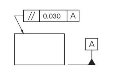
The condition of a surface or axis which is equidistant at all points from a datum of reference. All points on a surface are to be parallel to a given datum, within a specified tolerance.
TRUE POSITION:
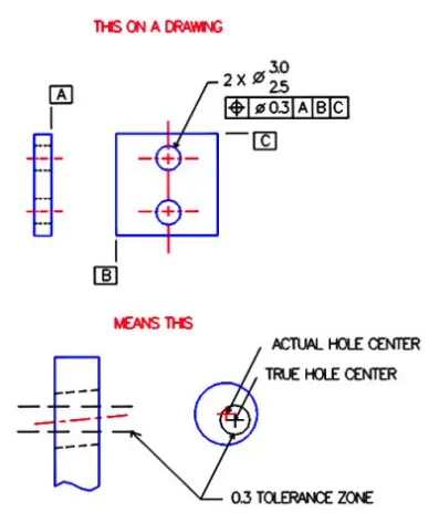
A zone within which the centre, axis, or centre plane of a feature size is permitted to vary from its true position. A position tolerance generates a tolerance zone that confines the centre, centre plane or axis of a feature of size. It is also capable of confining a surfaces within or outside of a boundary known as virtual condition.
CONCENTRICIRY:
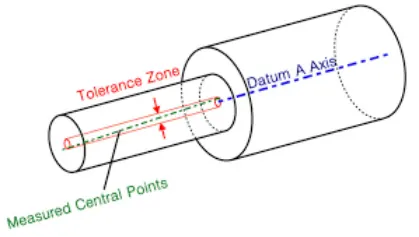
A cylindrical tolerance zone whose axis coincides with the datum axis and within which all cross-sectional axis of the feature being controlled must lie. Concentricity is a geometric control of the median points of all diametrically opposed elements of a figure of revolutions.
SYMMETRY:
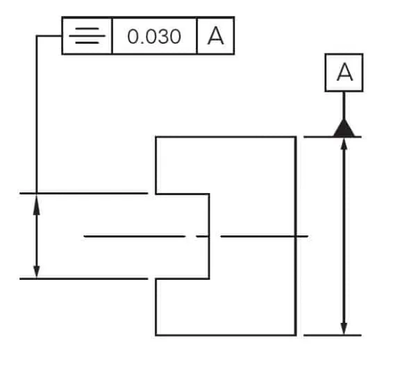
Symmetry is that condition where the median points of all opposed or correspondingly located elements of two or more features are congruent with the axis or centre plane of datum feature.
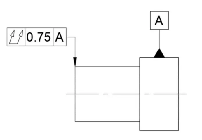
CIRCULAR RUNOUT:
A composite tolerance used to control the relationship of one or more features of a part to a datum axis during a full 360-degree rotation about the datum axis.
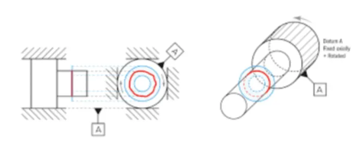
TOTAL CIRCULAR RUNOUT:
All surface elements across the entire surface of the part must be within the runout tolerance.
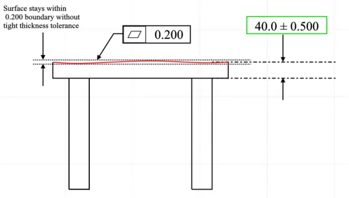
FLATNESS:
A two dimensional tolerance zone defined by two parallel lines within which the entire surface must lie. Basically all the surface elements are constrained to lie within two parallel Planes, separated by the tolerance.
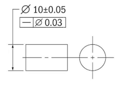
STRAIGHTNESS:
A condition where an element of a surface or an axis is a straight line. One of the surface elements is constrained to lie within two parallel surface planes separated by the tolerance. This means that if any line across the surface is within two parallel lines, the part is acceptable.
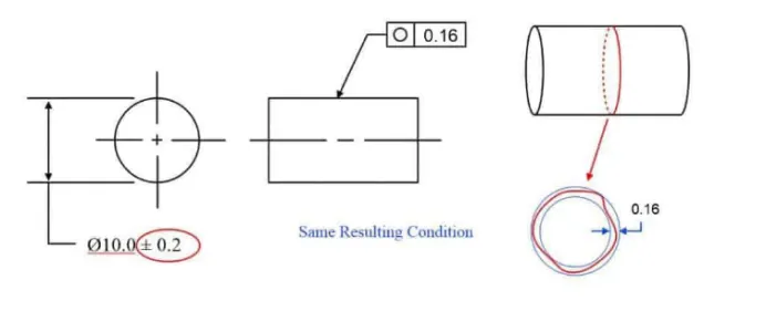
CIRCULARITY:
A condition on a surface of revolution where all points of the surface intersected by any plane perpendicular to a common axis or passing through a common centre are equidistant from the axis of the centre. All of the points on a cylindrical surface are constrained to lie within two circles.
CYLINDRICITY:
A condition on a surface of revolution in which all points of the surface are equidistant from a common axis. It is an extension to circularity that specifies the tolerance along the cylinder. It is a 3D form control which controls roundness, straightness and taper.