Week 9:- 2D Detailing Challenge
1.) What are the Drawing templates?
A drawing template enables you to create exact circles, squares, lines, arcs, and more without reaching for a compass, ruler, or protractor. It's a necessary tool for executing clean-lined blueprints, sketches that demand precision, or crisp compositions for bullet journals.
Templates have pre-dimensional holes that are in the right scale, so engineers can accurately draw a specific symbol or sign. Letter templates can be used to draw text (such as digits and letter characters), while others can be used to draw circles and arcs. Drawing templates are the files of frame & title block which convey the design information that are used to generate 2D drawing from 3D parts.Neat and Detailed Drawing templates convey more information from designed to manufacturer. So, we can avoid misunderstanding and make a very effective parts, which saves time & money.Drawing templates are change as per the company standards.Drawing templates are provide by the customer at the starting of the project , If not then should finalize at starting of project.
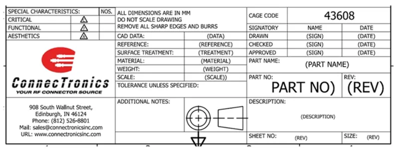
Drawing templates has number of information such as:
- Company name
- project Name
- Sheet size
- Sheet number
- Angle of projection
- Revision Number/ Latter(if its revision drawing)
- Signature or name of drawn by, checked by, responsible engineer & approved by
- parts detail.
- Quantity
- Additional nots (Surface finish, heat treatment, material detailed)
- Additional nots (Surface finish, heat treatment, material detail, etc.)
- Scale, data, unit of measurement.
2.) What do you understand by Angle of projection?
- The so-called equal-angle projection is that the angle between any two lines on the projection plane is equal to the corresponding two-line segments on the ellipsoid, that is, the angle deformation is zero.
- Technical drawing usually consist of various two dimensional views to define an object, this is known as orthogonal projection. The two orthogonal projection methods used internationally are first angle projection & third angle projection.
- If some detailed of view can be inferred from another, then you don’t bother to draw that view.
- The angle at which an observe drawn an object to convert it from 3D to @d plane such as real object image to a plane is known as angle of projection.
- It's wat of showing a 3D object on a 2D piece of paper , & it shows what a part looks like each direction - top, bottom, left & right.
ORTHOGRAPHIC REPRESNTAION
- According to the rule orthographic projection, Horizontal plane is rotated in the clockwise to draw a projection view of 3D object on 2D plane.
- Orthographic projections are 3D representation of 2D objects.
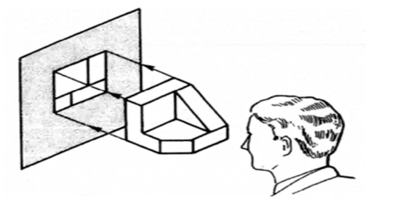
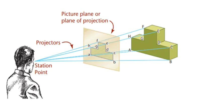
- Features of 3D parts are presented on flat plane, through the outline of part had been projected onto a screen.
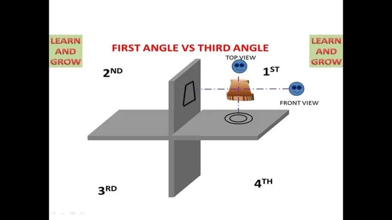
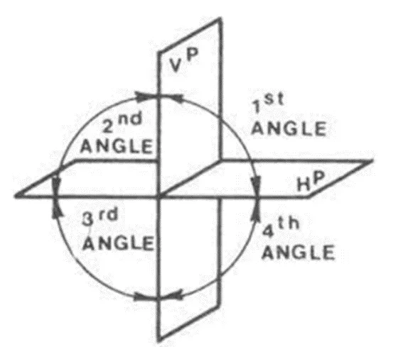
- From the above image, the viewing angles are splint into quadrants of first angle, second angle, third angle & fourth angle.
- First angle quadrant & third angle quadrant are used as they are the pure & proper views of the design,
- The second angle quadrant & fourth angle quadrant are combination of first & third angle projection & can cause confusion to the reader.
- The principle of first angle projection is known. In that image the observer look at the 3D shape 7 projects the image onto a screen behind the component.
3.) What is the First angle & Third angle projection? and why can't we use the 2nd and 4th angle of projection?
- First Angle Projection
The First Angle Projection schema imagines the object in the first quadrant. One can place an object on the top of the horizontal plane and at the front of the vertical planes. The first angle projection is utilized mostly in India and various European countries. It places the object between the projection planes and the observer. You can take the plane of projection to be solid in the first angle projection.
Method Of Projection:
When you divide a plane into four quadrants, you can place any object in the first quadrant in a first angle projection schema.
First angle & Third angle projection kay Difference:
The use of orthographic projection is the representation of a 3D object on a 2D plane. This projection system makes the utilization of parallel lines for protecting the 3D object views on a 2D plane. According to the orthographic projection rule- one needs to rotate a horizontal plane in the clockwise direction in order to draw a protectional view of any 3D object onto a 2D plane.
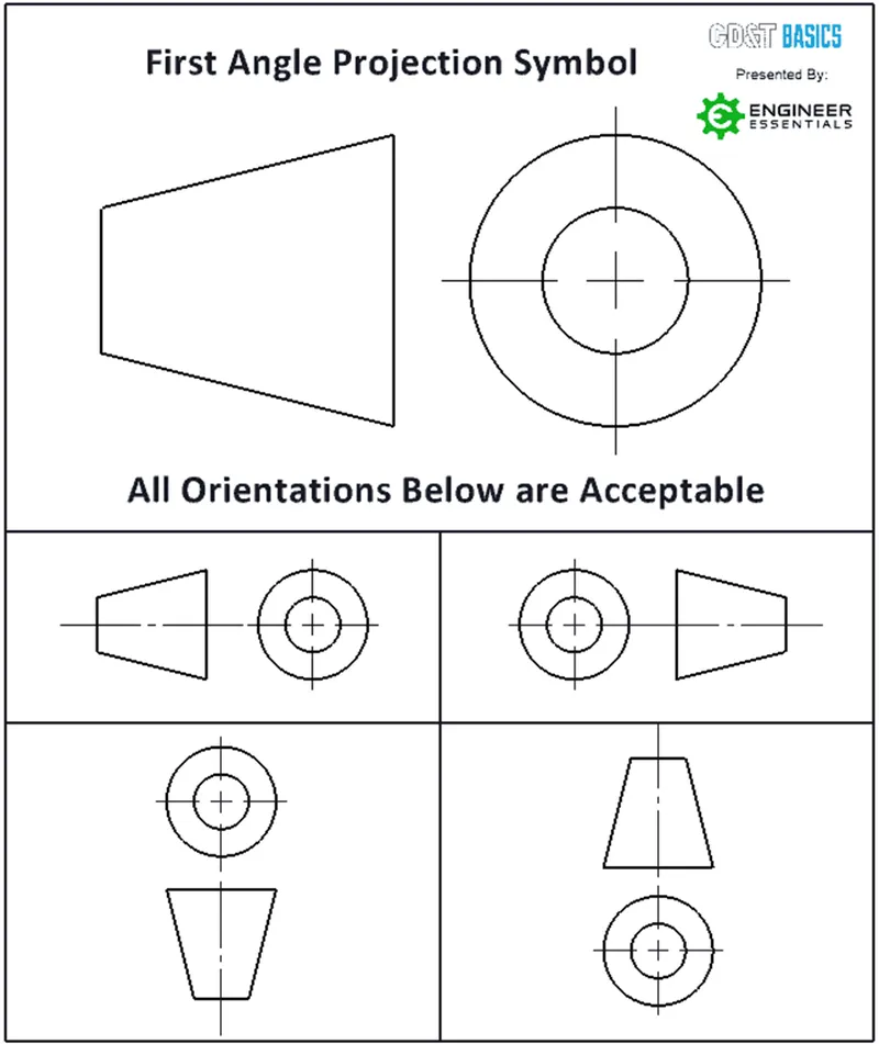
It places the object between the observer and the plane of projection for the first angle projection.
Widely used in India, Europe, Canada.
- Third Angle Projection :
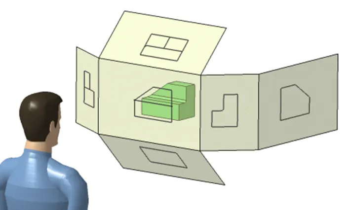
The Third Angle Projection schema imagines the object in the third quadrant. One can place an object on the bottom of the horizontal plane and behind the vertical planes. The first angle projection is utilized mostly in the United States. It places the object between the observer and the object. You can take the plane of projection to be transparent in the third angle projection.
Method Of Projection:
When you divide a plane into four quadrants, you can place any object in the third quadrant in a third angle projection schema. In the third angle projection schema, the top view sits at the top of the front view, and the right view sits on the right side of the front view.Widely used in Australia and the United States.It places the object between the observer and the object for the third angle projection.
why we use the 2nd and 4th angle of projection:
In Mechanical Engineering, drawings are made either in first angle projection or in third angle projection. We do not make drawings in second or fourth angle projection. We will discuss the reason behind doing so in this article..
Let us first understand the concept behind the angle projection system. Imagine you have Vertical Plane (VP) and Horizontal Plane (HP) (Perpendicular to each other), now we have 4 quadrants. For 1st angle projection system, we place object in 1st quadrant, for 2nd angle projection system, we place object in 2nd quadrant and so on.
In Second quadrant, Vertical plane (VP) lies in between object and observer. Therefore, front view of the object will lie on vertical plane whereas top view will lie on horizontal plane. As per rule of projection when horizontal plane is rotated 90 degree in clockwise direction, top and front view will overlap.Overlapping projection views create confusion in the drawing. Therefore 2nd angle projection system is not used. Similarly, when object is placed in 4th quadrant both top and front view will overlap. Therefore, fourth angle projection is also not used. To sum up, because of overlapping of front and top views 2nd and 4th angle projections are not used. First and third angle projection systems are recommended for orthographic projections
4.) What is GD&T? What are the benefits of GD&T?
A design model is an idealized representation of a part design. However, the design model by itself does not fully define the design. Due to imperfections in manufacturing and inspection processes, physical parts never match the design model exactly. An important aspect of a design is to specify the amount the part features may deviate from their theoretically exact geometry (as defined in the design model).
Geometric dimensioning and tolerancing, often referred to as GD&T, is a symbolic language used on engineering drawings and models to define the allowable deviation of feature geometry. The language of GD&T consists of dimensions, tolerances, symbols, definitions, rules, and conventions that can be used to precisely communicate the functional requirements for the location, orientation, size, and form of each feature of the design model. Thus, GD&T is an exact language that enables designers to “say what they mean” with regard to their design models. Production can then use the language to understand the design intent and inspection looks to the language to determine set up requirements.
Geometric Dimensioning and Tolerancing is a system for defining and communicating engineering tolerances and relationships. It uses a symbolic language on engineering drawings and computer-generated three-dimensional solid models that explicitly describe nominal geometry and its allowable variation.
The benefits of GD&T:
GD&T, a vital part of complex machining, offers a number of major advantages:
- Saving Money — GD&T enhances design accuracy by allowing for appropriate tolerances that maximize production. For many projects, the process provides extra or bonus tolerances, further increasing cost effectiveness.
- Ensuring Dimensional and Tolerance Requirements — By explicitly stating all design requirements, a thorough GD&T process guarantees accurate fulfillment of all dimensional and tolerance specifications.
- Assisting Digital Design Methods — Clear, concise GD&T data is readily adaptable to digital design programs, including nearly universally used 2D and 3D CAD files.
- Offering Uniformity and Convenience — As a single, consistent language, GD&T reduces guesswork and interpretation while ensuring consistent geometries across design and manufacturing.
- Providing Accurate Communication — Today’s intricate designs demand the most accurate and reliable communication. GD&T enables designers, manufacturers, and inspectors to communicate clearly with one other, saving time and making the process more efficient.
While many applications benefit from GD&T, there are certain situations in which the process provides fundamental assistance, including scenarios in which critical or interchangeable parts fit into a larger assembly, tolerance analysis needs simplification, or the project requires functional gauging techniques.GD&T replaces complex description notes with a single symbol or set of symbols, allowing for effortless reference and fast, precise communication. The process provides additional clarity when clients are working without a standard interpretation or tolerance, making even the most in-depth and complicated projects easier to complete.
5.) Explain all the symbols used in GD&T?
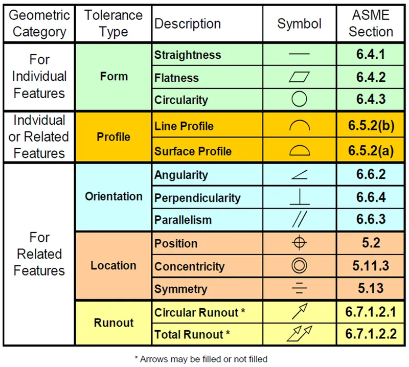
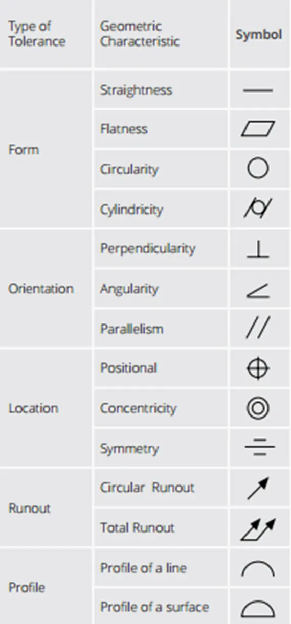
There are a total of fourteen GD&T characteristics & the symbols that represent them are shown in the symbol below.
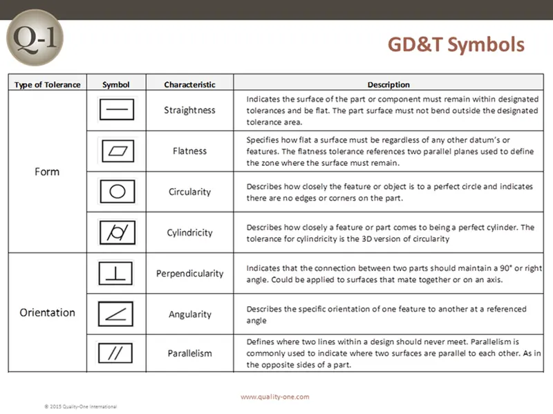
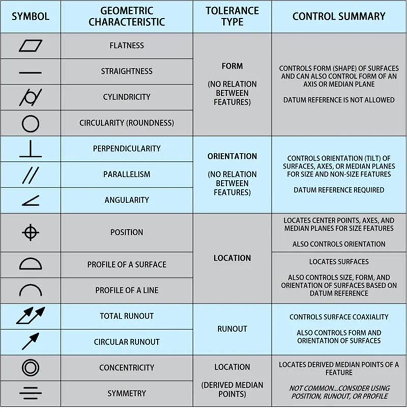
Form tolerances: Control the "shape " of features & are often used as a refinement of size.
Orientation tolerances: Control the "tilt" of feature & are always associated with basic angle dimensions, often used as a refinement to location. If applied to surfaces, orientation tolerances also control from.
Location tolerances: Control location are always associated with basic linear dimensions. Position locates & orients the median plane or axis of features of size. Profile locates feature surfaces. Profile is the most powerful characteristics of all, & also controls orientation & form.