Week 9:- 2D Detailing Challenge
1. What are drawing templets ?
Drawing templets are the blue print which are useful in making the design and are used for manufacturing the product.
- This are the templets according to the customer specification.
- This are the blueprints used for designing the different unit
- There are many templets that are available on the templet which are useful for the various manufacturing.
- Preparing the templet makes saves time.
- This also gives the detail about the angle projection to be used.
2. What do you understand by angle of projection ?
- The angle of projection is the prespective which shows the 3 dimensional part in a 2 dimensional plane
- The angle of projection is allows the manufacture to understand the part dimension
- The angle of projection shows part in front, top and side view
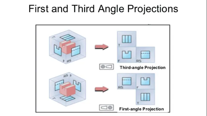
- The are two angle of projection used in engineering drawing: First angle projection and Third angle projection
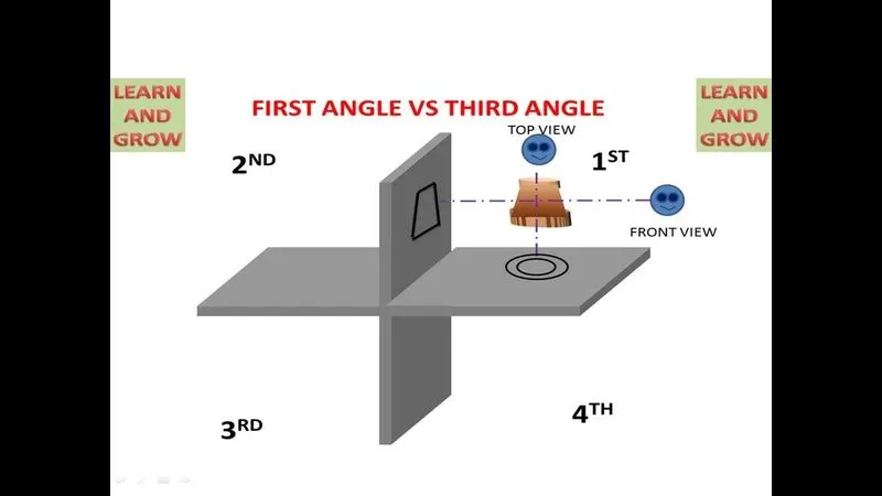
3. What is first angle and third angle projection ? Why don't we use 2nd and 4th angle projection ?
First angle projection:
- In this projection, the object is placed in the first quadrant.
- The object is between the observer and the plane of projection
- The plane of projection is opaque
- Front view is on the top of the horizontal axis
- Top view is on the bottom of the horizontal axis
- Right view is on the left side of the verticle plane
- Left side is on the right side of the verticle plane
Third angle projection:
- In this projection, the object is placed in the third quadrant
- The plane of projection is between the observer and the object
- The plane of projection is trasperant
- The fornt view is on the bottom of the horizontal axis
- top view is on the top of the horizontal plane
- Right view is on the right side of the verticle plane
- Left view is on the left side of the verticle plane
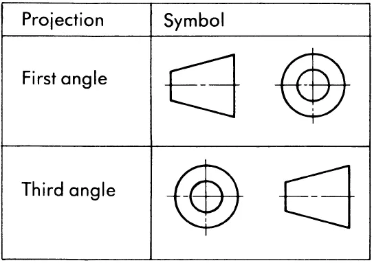
Why is 2nd and 4th angle is not used?
When the 3 dimensional drawing is to be viewed on a 2 dimensional plane, the horizontal plane is to be rotated clockwise according to the orthographic rule.
Therefore, the top view and the side view will overlap making the view confusing.
4. What is GD&T ? What are the benefits of GD&T ?
Geometric Dimensioning and Tolerancing is the way to define the Geometry, dimensions and the tolerance of the product.
GD&T is symbolic language which helps engineer and manufacturer to make a proper product
It ensures that the manufacturer is making the part as per the design criteria of the customer.
ASME Y14.5M-2009 standard is currently being followed.
Benefits of GD&T:
- Save cost of manufacturing
- Save manufacturing time
- Reduces waste
- Avoids mistakes
- GD&T makes inspection easy
- Easy communication between the engineer and the machine operator.
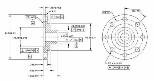
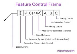
GD&T is given by using a feature control frame
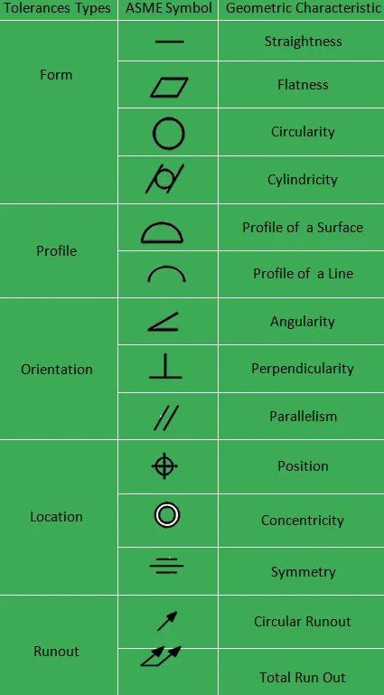
5. Explain all the symbols of GD&T ?
- Form tolerances: This tolerance indicates the shape of the part
- Straightness: This symbol gives the information about the how straight a surface or a line. The line should lie between two parallel lines.
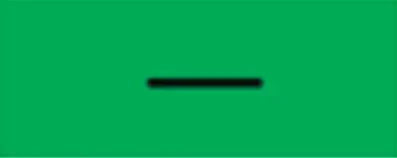
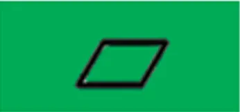
- Flatness: This symbol gives information about the how flat a surface. The surface should lie between two parallel planes.
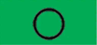
- Circularity: The circularity is the symbol which indicates that a circle must lie within the boundries of the two concentric circles
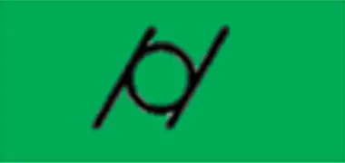
- Cylindricity: This indicates that the surface of the cylinder must lie within the boundires of two concentric cylinder.
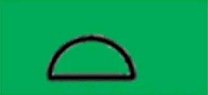
2. Profile:
- Profile of a Surface: The profile of the surface indicates that the surface should lie between the boundries of the two other surfaces. Here the surface can be in any form
- Profile of a line: This indicates that the a line is to be within the boundries of two other line. This is different from straightness in a way that the two lines are necessarly straight.
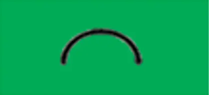
3. Orientation Tolerances: This tolerances are used to define the orientatojn of the surface or the line.
- Angularity: The angularity of the indicated the angle at which a line, plane or a surface must be with respect to a datum plane.
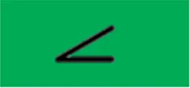
- Perpendicularity: The perpendicularity indicates that the surface or line must be 90 deg. with respect to the datum plane or surface.
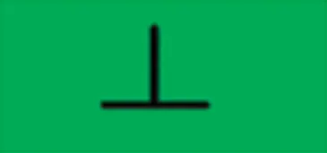
- Parallelism: This indicates that a line or a surface must be parallel with respect to the datum plane or surface
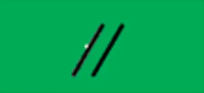
4. Location tolerance: The location tolerance is used to define the locatoin of a axis or a plane.
- Position Tolerance: This indicates the position of a center axis, or midplane, or surface.
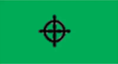
- Concentircity: This gives the information about the concentricity of two circles
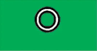
- Symetricity: This indicates that the plane must line within two parallel planes.