Advanced Sheet Metal Design Using NX Cad Challenge_2_Box Assembly
Design of Box assembly using NX 12
Objective:
- Create box assembly using NX 12 Software
- Create a flatpattern of the box assembly
- Make a Drawing on an A4 sheet
Introduction:
- In this challenge a sheetmetal box is created in NX 12 software and a lid is created for the box. Various commands are used for the creation of the box. The box is then made into flat pattern and drafted on an A4 size sheet.
Design methodology:
- Make a shetch on XY plane --> Make a rectangle 150 by 200 mm in dimension --> Use Tab to make a sheetmetal of 1 mm thick --> Used Flange to make a flange on both edged with bend radius of 10 mm lenght: 200mm --> Make anorher flange on previous flanges with bend radius: 10mm lenght: 70mm --> Used Close corner with Type: close and relief; treatement: close; Overlap: close; Gap: 0mm --> Make a flange on previous flanges with bend radius: 0mm; length: 0.02mm --> Make a another Flange of Length: 6.5mm; bend Radius: 0.5mm; Length reference: inside; Inset: Bend outside --> Do the same on the other flange --> Make a Hem Flange Type: open; Inset: Bend outside; Bend radius: 0.5mm; Flange length: 5mm --> Do the same on the other flange --> Use Mirror Body to mirror the part along the YZ plane --> Used Unite to make the part body into one --> Make a Sketch on one face --> Use Dimple feature --> Depth: 2mm; Depth Reference: Inside; Side Wall: Material Outside --> Use Mirror Feature to mirroe the sketch and the dimple to the other face --> Make another sketch on the base of the box and make a dimple --> make four beads on the base of the Box --> Use Datum Plane make a plane 203mm parallel to XY plane --> Make a sketch on the new plane --> Make a Lid By using TAB Thickness: 2mm --> make a flanges on the long edges --> Length: 3mm; Length Reference: Web; Inset: Material Outside --> Do this for the other edge as well --> Darw a sketch on the smaller side of the box --> Make rectangle 20 by 55 mm --> Use tab and make a part --> Use BREAK CORNERS to make rounded corners --> Used flange Length: 4mm; Angle: 40deg.; Length reference: Web; Inset: Material Outside; Bend Radius: 0.5 --> Make another flange on the same flange --> Length: 4mm; Angle; 40deg.; Length Reference: Web; Inset: Material Outside; --> Make a HEM Type: Open Loop; Inset: Bend Outside; Bend Radius: 5mm; Sweep angle: 325deg.; --> Unbend the hem and the flange --> Draw a sketch on the part --> Make verticle lines 14mm apart --> Use Normal Cut to cut the flanges --> Rebend the Flange and the Hem --> Use mirror feature to mirror the Tab, Flange and the hem along ZX Plane --> Make a Sketch on the Lid --> Make a tab --> Make a flange --> Length: 13mm; Angle: 39deg.; Length Reference: Web; Inset: Material Outside; --> Make a Sketch on the Flange --> Make it constrained with the sketch for the previous cut --> Use norma cut to make the cut --> Use FlatPattern to make a flat pattern --> Make a drawing on the A4 sheet.
Description:
- Tab: This feature is used for making a sheetmetal
- Flange: This is used for making flanges on the sheetmetal
- Hem: This is used for bending the sheet metal
- Sketch: This is used for making a sketch on the plane or face
- Normal Cut: this is used for making cut outs in the sheetmetal
- Break Corners: This is used for makin rounded corners on the sheet metal.
- Mirror Body: This is used for making copy of a part along a plane.
- Mirror feature: This is used for copying features along a plane.
- Close corners: This is used for closing the open corners.
- Datumm Plane: This is used for making a new plane with refernce to an existing plane.
Part Images:
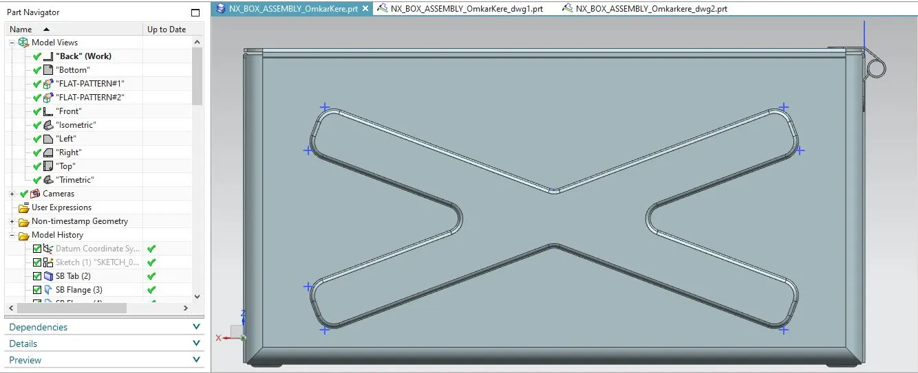
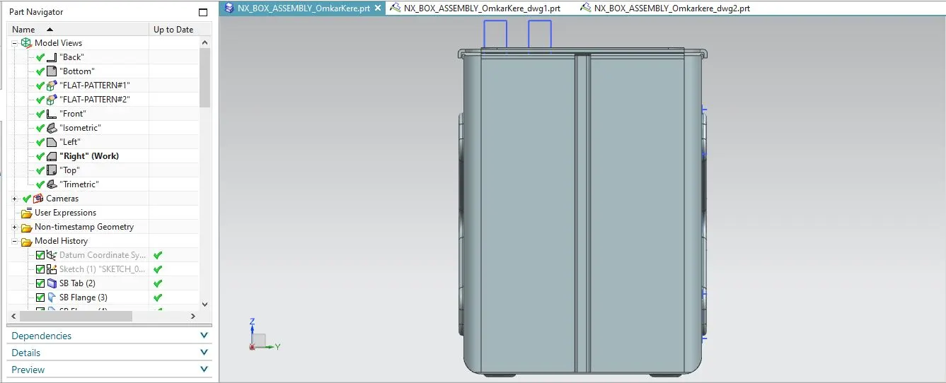
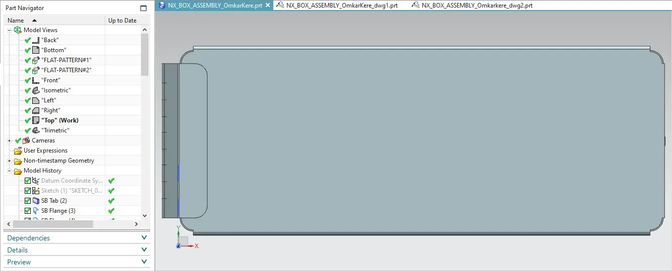
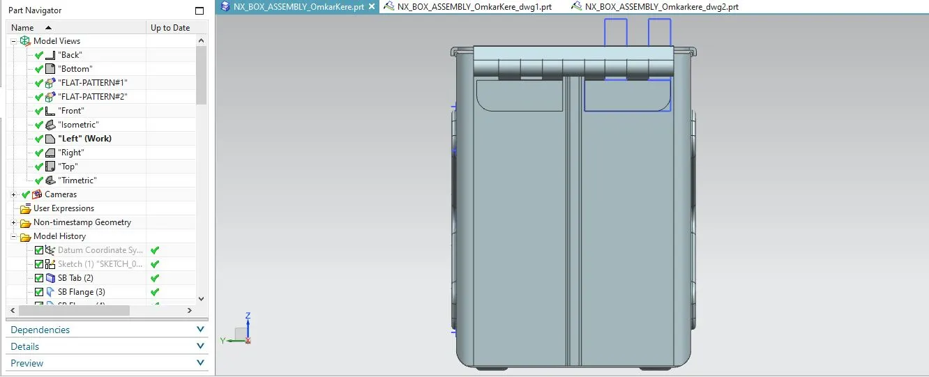
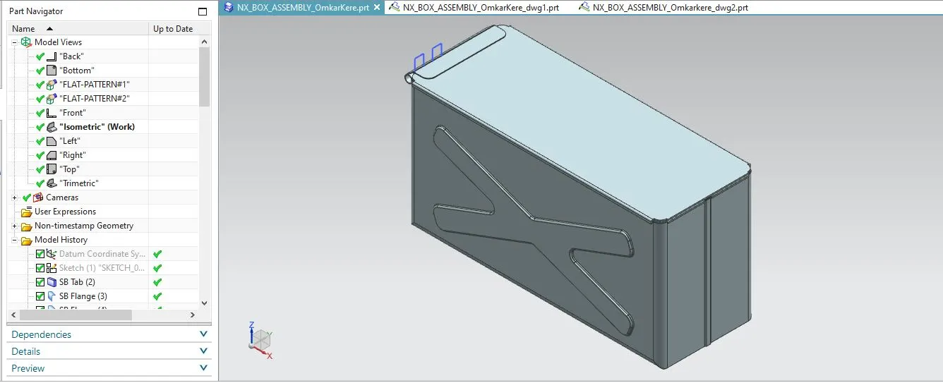
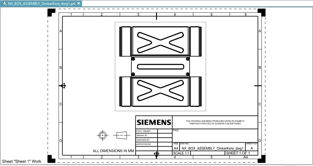
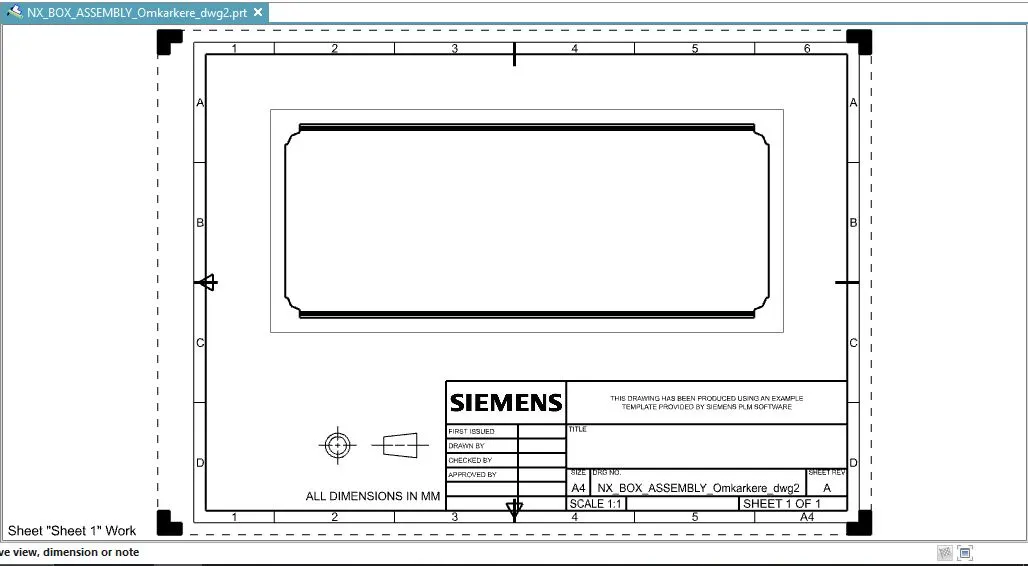
Drawing Sheet:
Conclusion:
The Sheet Metal box assembly was created in NX 12 using the above features and the Drawing was made on an A4 size sheet.