Advanced Sheet Metal Design Using NX Cad Challenge_1_Casing Design
Design of casing using NXCAD 12 software
Objective:
- To design a sheetmetal casing using NX 12.
- Draft the part drawing on an A4 size paper.
Introduction:
NX 12 is a sheetmetal design software used for making complex sheetmetal parts and then draft them on a paper.
Design Methodology:
Start the NX 12 --> Create a sheetmetal Part --> Start a sketch on the XY datum plane --> Make a rectangle of 60*50mm and exit the sketch --> Select Tab option make the sheet 1mm thick --> Sketch on the sheet and make a rectangle of 5*40mm --> Rectangle should be coincident with the left edge and symetric to X-axis --> Cut the rectangle throuh the sheet using NORMAL CUTOUT --> Draw two lines one 10mm away from the upper edge and other 10 mm away from the lower edge --> Use dthe BEND option to bend the two sides using the sketches as the reference --> Add flanges using FLANGE to the Four ends two inwards and two outward --> Unbend the Part using UNBEND option --> Make a sketch on the Small flange and create a point in the middle --> Make similiar points on the other flanges --> Use HOLE option and select the four points --> Use Screw type: General Screw Clearence Type --> Screw size: M2 --> Fit:H13 --> Depth Limit: Through Body --> Make a sketch on the XY-Plane --> Make a cross with half length 5mm and center at 0,0,0 co-ordinates --> Use STUDIO SPLINE option --> Select all 16 points clockwise -->make a spline -->Use MOVE CURVE option and rotate the spline at 45deg. angle --> Use DIMPLE option --> Select the spline--> depth: 1mm --> Side wall: Material Inside --> Change all rounding values to 1mm --> make a dimple--> Make a circle on the XY-plane --> Diameter: 5mm --> Used BEAD option --> Set Depth: 1mm --> Radius: 1mm --> Rounding: 1mm --> Make a bead --> Use MIRROR FEATURE option and mirror the bead along YZ and XZ plane --> Rebend the part using REBEND option --> Create a flat pattern --> Select central flat face --> Make a new drawing (Draft file) --> Paper size:A4 --> Select BASE VIEW option --> FLATPATTERN#1 --> scale: 2:1 --> Save.
Description:
- Sketch: This tool is used to make sketches on the Datumm plane or the surface of the part.
- Rectangle: This is used to make a rectangle.
- Line: This is used to make a line.
- Circle: This is used to make a circle.
- Tab: This is used for making a sheet metal with a certain thickness.
- Normal Cut: This used for making cuts in the sheetmetal.
- Bend: This is used for makng bends on the parts with a reference curve.
- Flange: This is used for making Flat flanges at an angle or a planar face.
- Unbend: This is used to unbend the already bended part.
- Hole: This is used for making holes in the sheetmetal part
- Studio Spline: Used for making spline along the points of a sketch.
- Move Curve: To move or rotate the curve.
- Dimple: Used for making punch in the sheetmetal.
- beads: Used for making beads
- Mirror feature: Used for mirroring the existing features on the sheetmetal.
- Rebend: This feature is used to rebend the unbended parts.
Part Images:
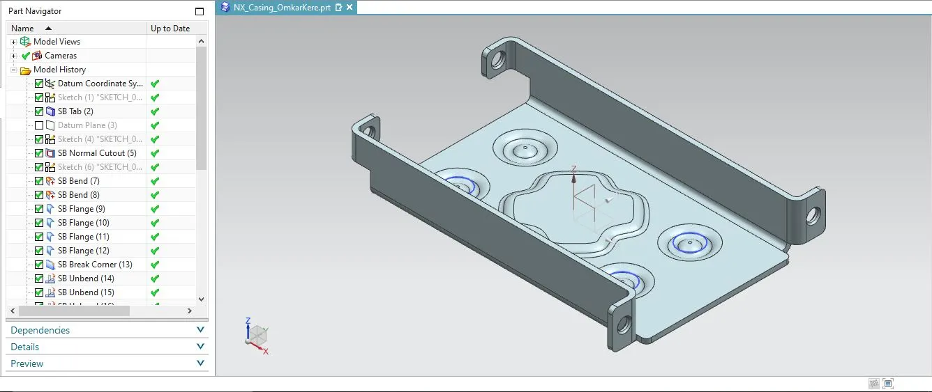
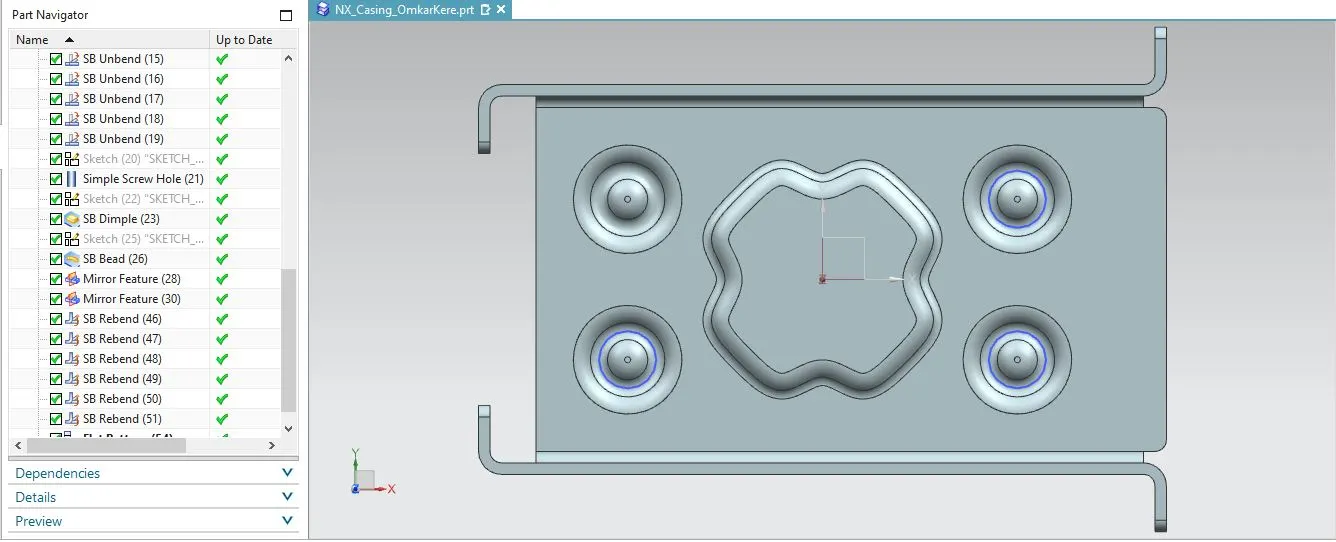
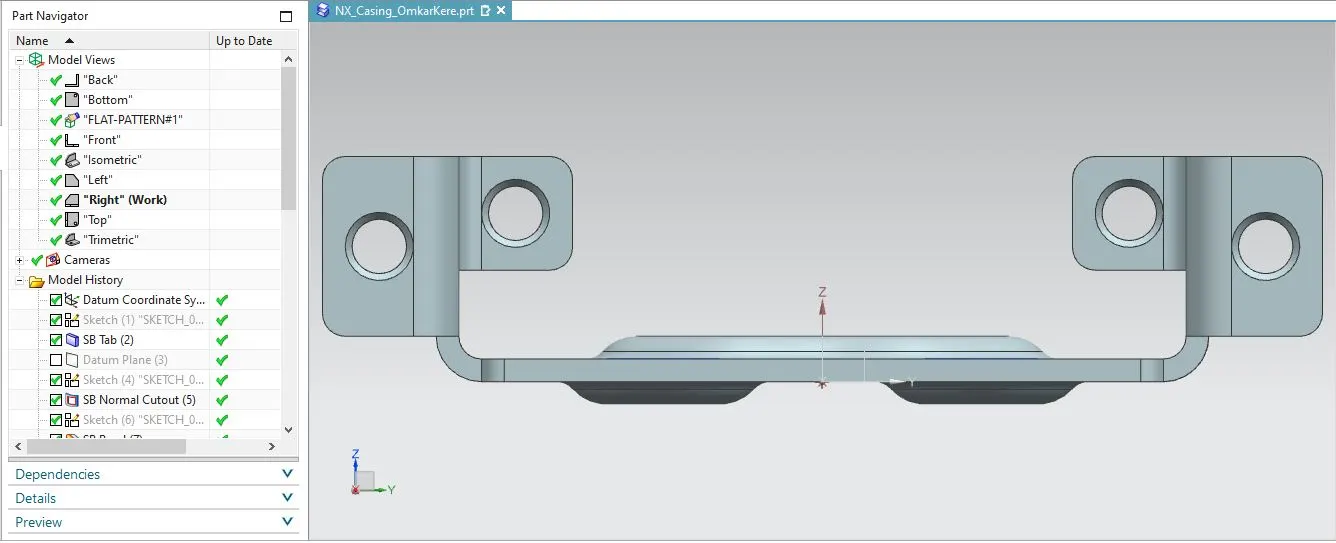
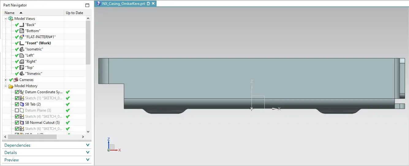
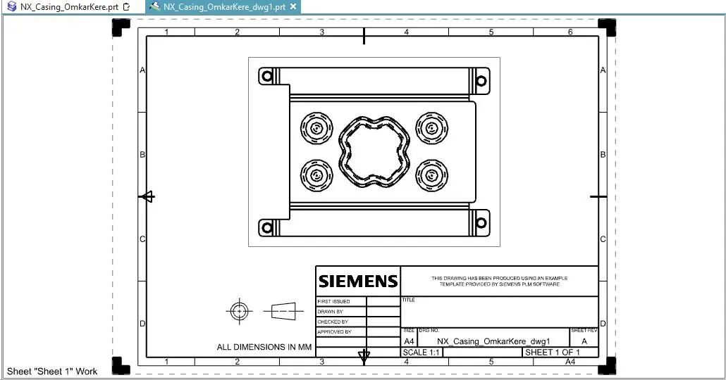
Drafting part on an A4 sheet
Create a new drwing file and chooose A4 size paper--> Goto Base view option and select the FLATPATTERN#1 and place it on the sheet.
Conclusion:
The part was created using NX 12 software and the part drawing was drafted on the A4 size sheet.