Assembly of Yacht
Design, assembly and rendering of Sunseeker Predator Yacth using Solidworks
Objective:
- Model the parts of a Sunseeker Predator Yatch using SolidWorks
- Assemble all the parts using solid works
- Give appropriate appearence to the parts in solidworks
- Render images using photoview 360
Introduction:
SolidWorks is a 3D modeling sofware which is used in many industries such as automobile, aeronautics, etc to create models of parts and assemble them into a final product. SolidWorks is a parametric modeling software; this mesan that the model can be altered in size anytime. In this project a Sunseeker Predeator Yacth is modeled starting with 1. Propeller 2. Radar 3. Hull 4. Garage Door 5. Front, Middel and Rear seat 6. Superstructure 7. Radar mast. After modeling these components the yacth is assembled in solidworks asswmbly. The assembled yacth model is then used for rendering.
Parts to me modelled:
- Propeller
- Radar
- Hull
- Garage Door
- Front seat
- Middle seat
- Rear seat
- Superstructure
- Radar Mast
- Tools and Features used:
- Line: This feature allows us to create a straight line. The line can be a solid line or a construction line.
- Circle: This feature allows us to create circles.
- Rectangle: This feature allows us to create squares or rectangles.
- Spline: This allows us to make curved lines
- Arc: This allows us to create arc.
- Projected Curve: This is used to make curve using two sketches.
- Split: This feature is used to split to bodies using a sketch.
- Trim: This is used to trim sketches.
- Extend: This feature allows us to extend the sketches.
- Extrude Bose: This feature allows us to create solid bodies.
- Extrude cut: This feature allows us to create cuts or holes of any shape in the solid body.
- Swept Bose: This feature allows us to make a solid body along a curve path or create a curved solid body.
- Mirror: This feature allows us to create exact copy of the solid body using a reference plane or face.
- Revolve: This allows us to create revolve solid body around an axis.
- Linear Pattern: This allows us to create a pattern in a straight line.
- Circular Pattern: This allows us to create a pattern in a circle
- Fillet: This is used to create circular edges.
- Chamfer: This is used to create inclined edges.
- Plane: This feature is used to create new planes.
- Loft: This feature allows us to make solid bodies with uneven geometry.
- Dome: This feature is used to make a dome shaped solid over a flat solidbody.
- Shell: This is use to make a hollow solid body.
- Mirror Entities: This is use to create a mirror of sketch.
- Split Entities: This is used to split a line into two or more parts.
- Shell: This is used to make hollow parts.
Surface Features used:
-
- Extruded Surface: This is used to make a surface from a sketch.
- Extruded Loft: This is used to make uneven surfaces.
- Surface trim: This is used to cut surfaces.
- Surface Sweep: This is used to create a surface along a curve or a line.
- Boundry Surface: This is used to make a surfaec from boundry
- Ruled Surface: This is used to make surafaces from the edges.
- Extend Surface: This is used to extend the existing surface.
- Surfece offset: This is used to offset any surface.
- Parts Moddelled:
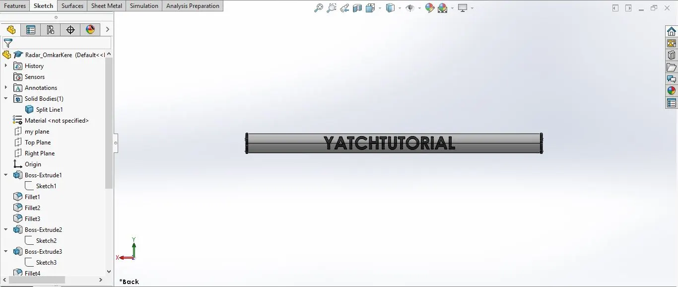
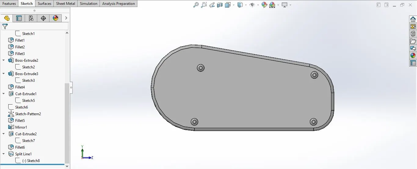
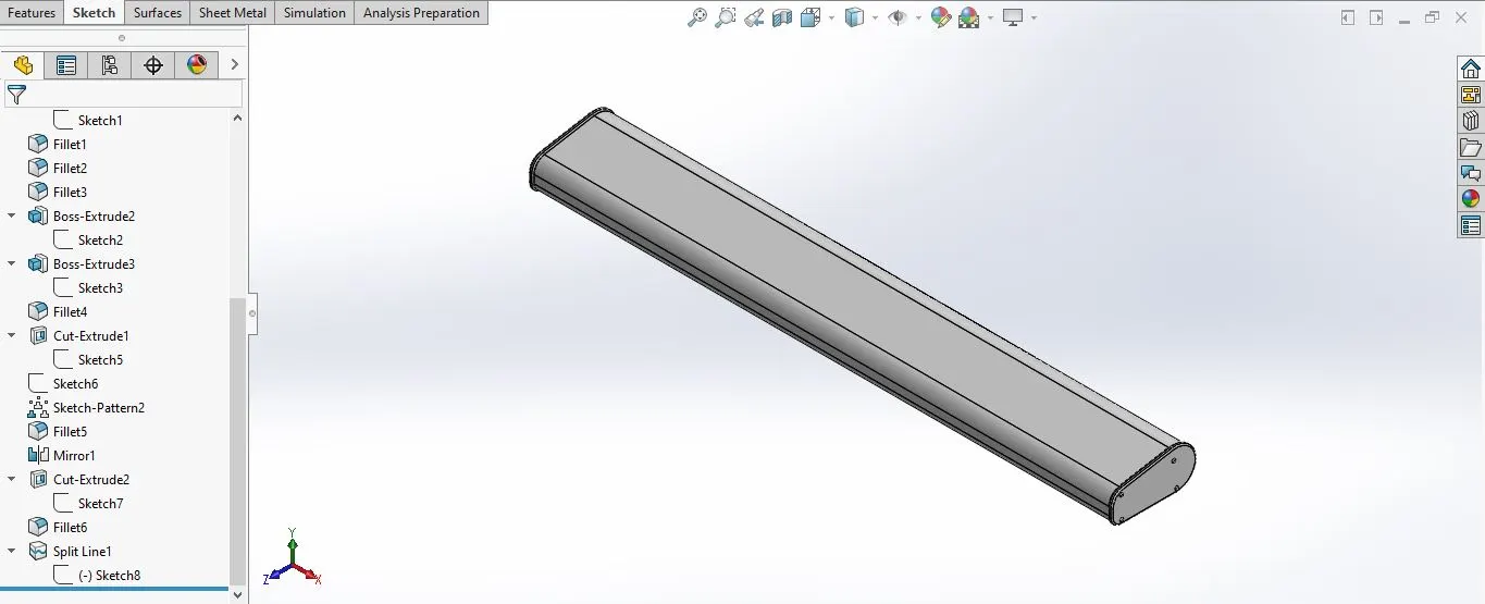
1. Radar:
This is the part used for the GPS and navigation of the ship.
Tools and features used:
- Sketch
- Extrude
- Fillet
- Line
- Polygon
- Circle
- Text
- Mirror
- Design methodology:
Make a sketch--> Extrude the sketch-->Offset the sketch to make the outer ends of the radar-->Extrude the sketch-->make circles for the screw--> Extrude the circles and amke a pplygon extrude cut--> Add fillets to the solid body-->Mirror the part to make the radar.
- Part with expanded feature tree:
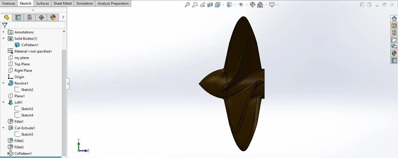
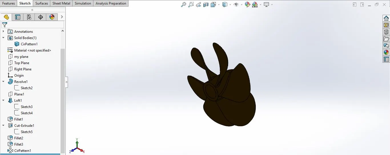
2. Propeller:
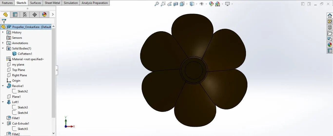
- This is used to impart forwar motion to the yacht.
Tool and Features used:
- Sketch
- Line
- circle
- Loft
- Rectangle
- Revolve
- Cirular Pattern
- Fillet
- Extrude cut
- Design Methodology:
Make a sketch on the plane-->Make the sketch according to the profile of the propeller-->Revolve the sketch on the axis-->make a reference plane on the surface of the revolve part-->make a rectangle on the palne --> Make aonther rectangle at different angle as per dimensions and relations using a reference plane-->Do an extrude loft and create blade-->Create fillet as per dimensions-->Make a circular pattern along the rim with 6 instances.
- Part with expanded feature tree:
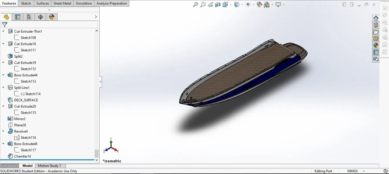
3. Hull:
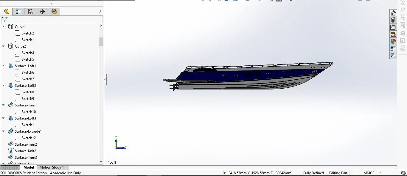
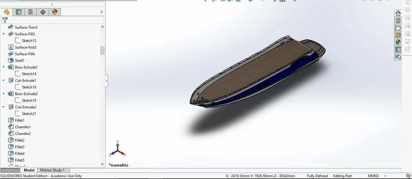
- This is the main structure of the yacht which is in contact with the water
Tools and Features used:
- Sketch
- Line
- Circle
- Projected Curves
- Linear Pattern
- Mirror
- Surface Extrude
- Surface Loft
- Extrude Cut
- Fillet
- Chamfer
- Sweep
- Surface Knit
- Surfae Trim
- Offset
- 3D Sketch
- Plane
- Shell
- Helix
- Design methodology:
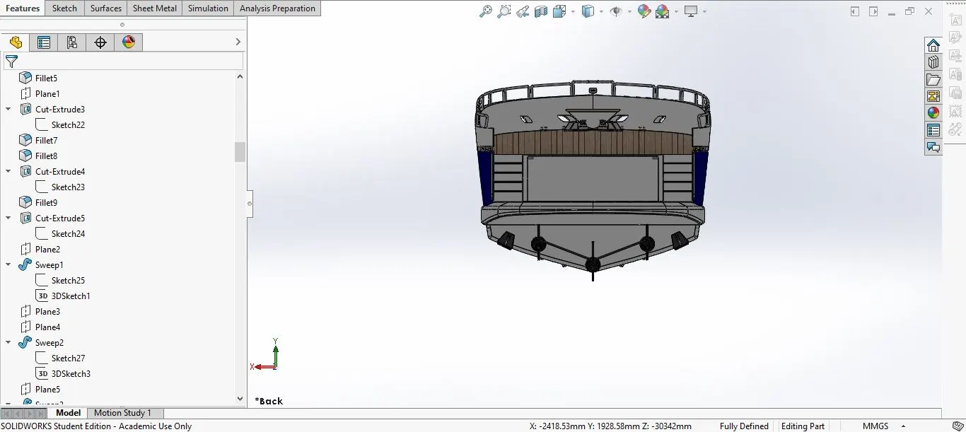
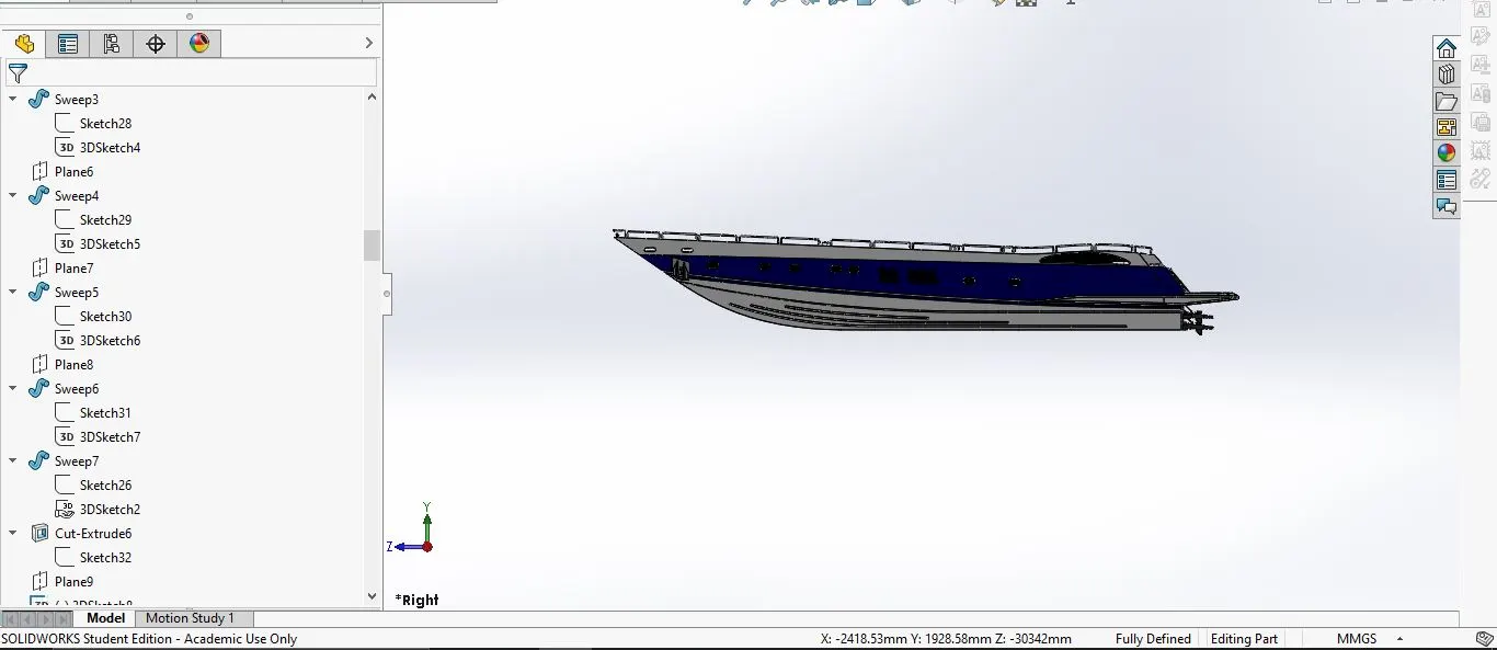
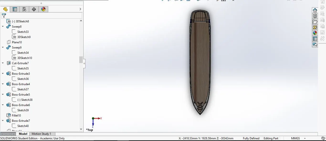
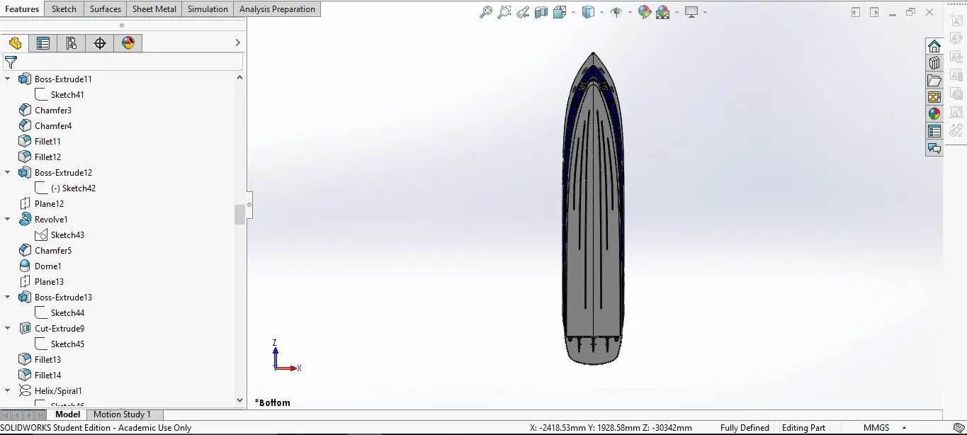
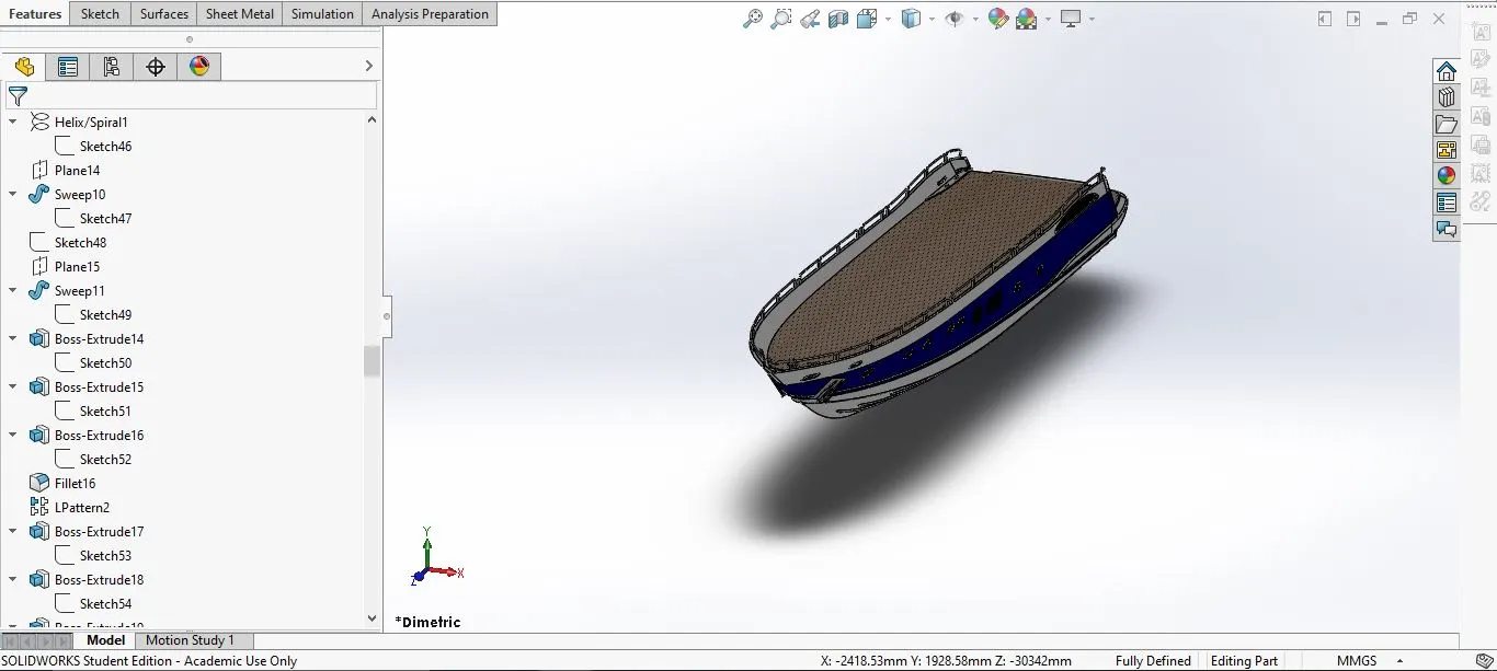
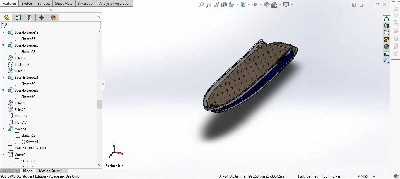
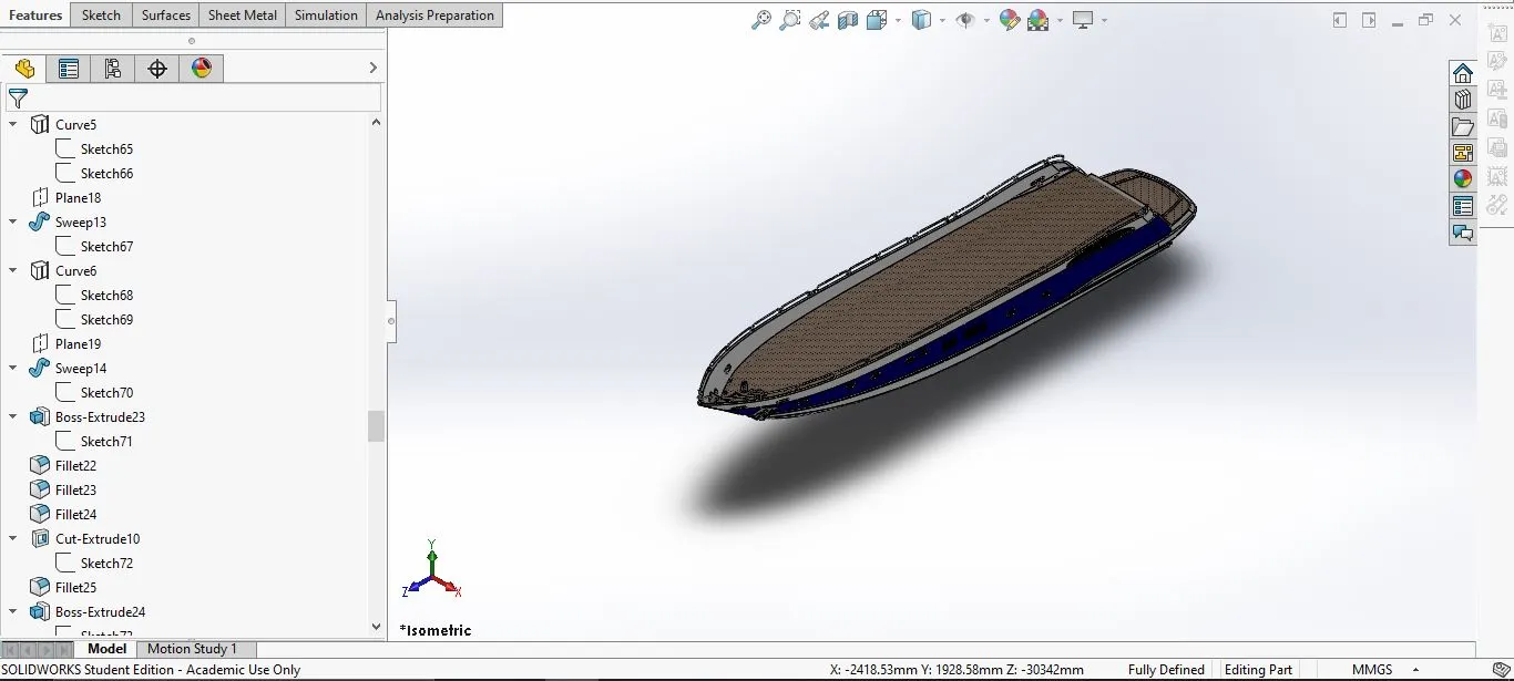
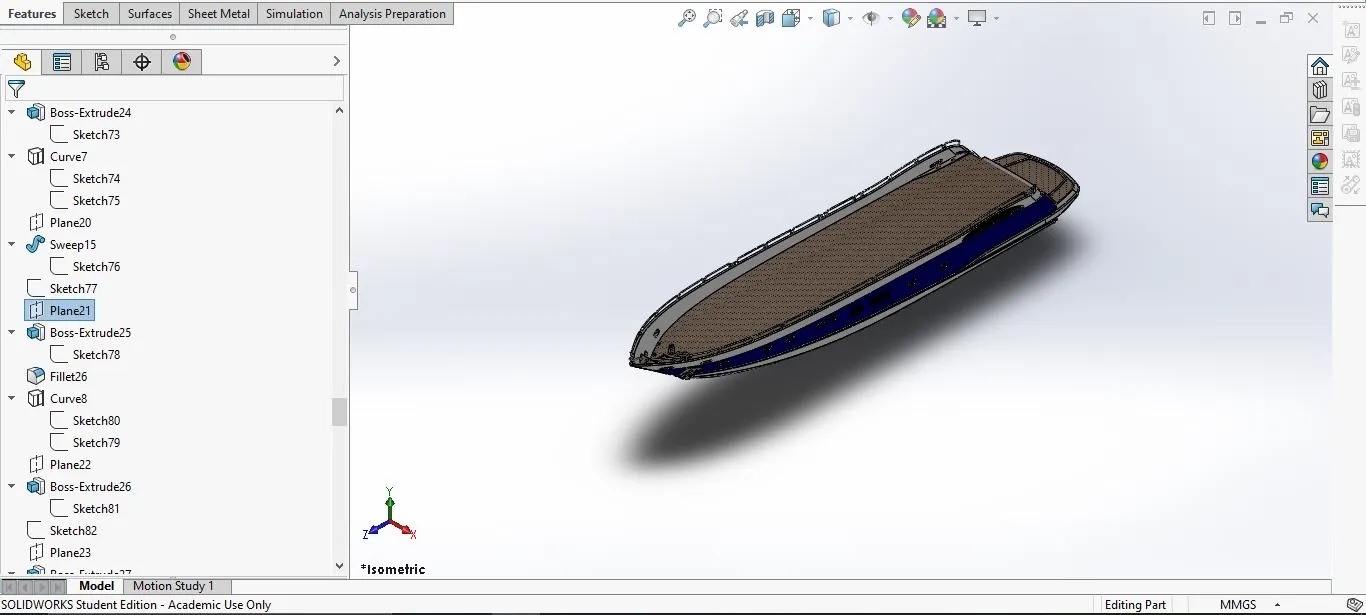
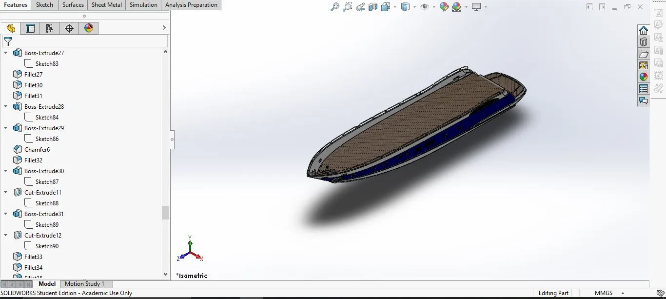
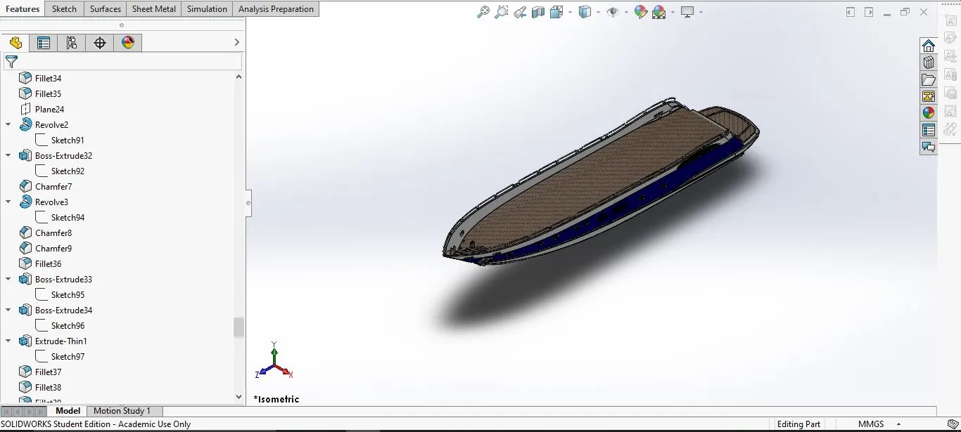
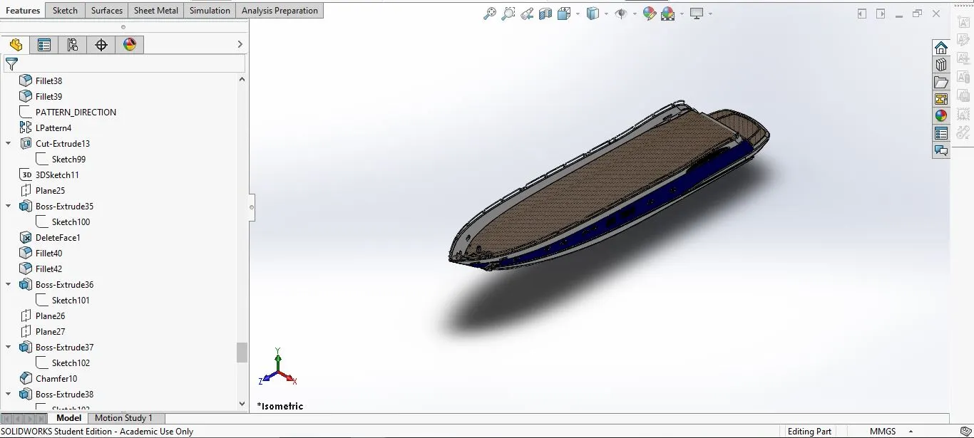
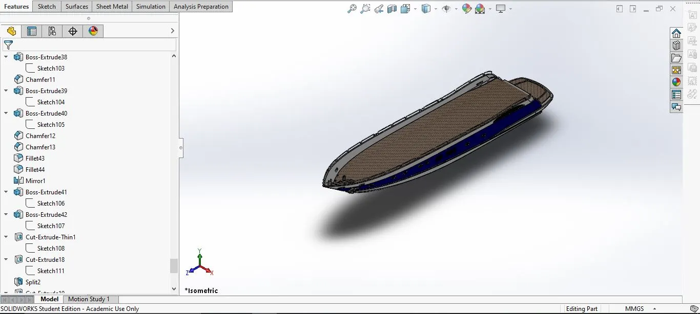
Select the sketch plane-->Using add sketch option add the sketch blueprints of the yacht-->Using the side and bottom blueprint make the sketch-->Make the first two sketches using the two blueprint and spline and line option-->Use projectrd curves option to make a curve-->Make two more sketches refering the two blueprints-->Make the curve using the projected curves -->close the sketch and used Surface loft option to make the surface-->Similiary make the other surfaces of the hull-->Use trim and knit options to join the surfaces-->make windows and cuts in the hull whereever in the blueprint-->MAKE the railing using projected curves and the sweep option-->Make the anchors-->Make the lights--Make the propeller support-->Cut the rear part of the hull portion to make the garage door-->Make the Hull a solid part --> Use mirror option to mirror the hull and make the entire hull-->Apply the decals where necessary.
- Part with expanded feature tree:
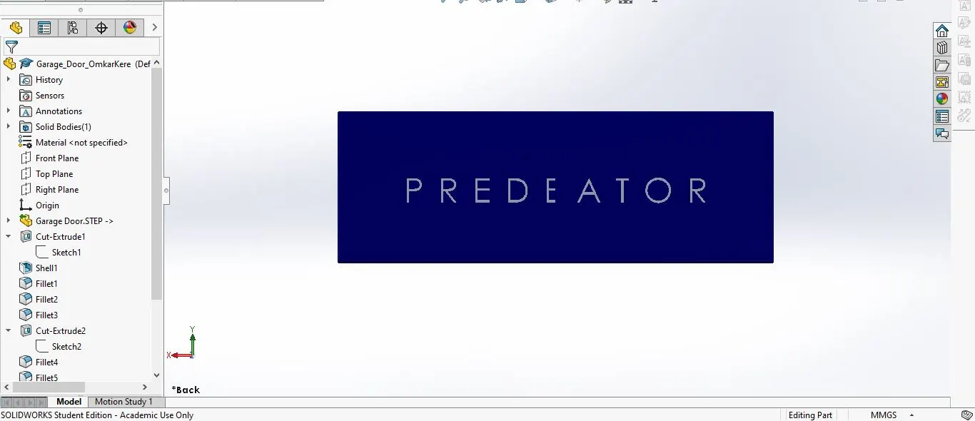
4. Garage Door:
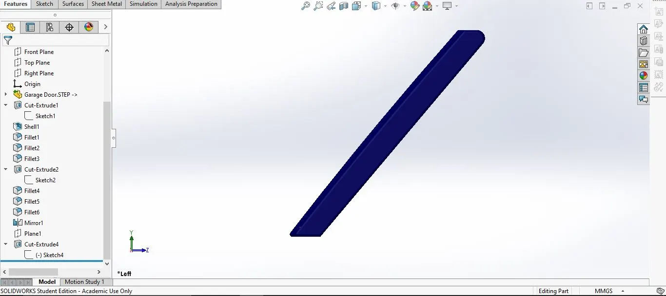
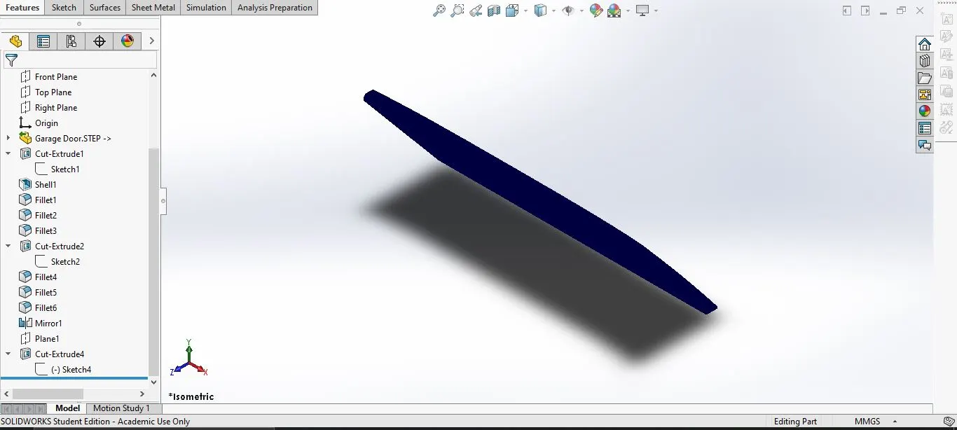
This is the main door of the garage.
- Tools and features used:
- Extrude cut
- Mirror
- Text
- fillet
- shell
- plane
- Design methodology:
Use the part cut from the hull sketch-->Perform the extrude cut to remove exsive portion-->Add fillets and chamfer where necessary-->do a shell operation the back of the door-->Mirror the door-->Use the text option to write a text-->Extrude cut the text.
- Part with expanded feature tree:
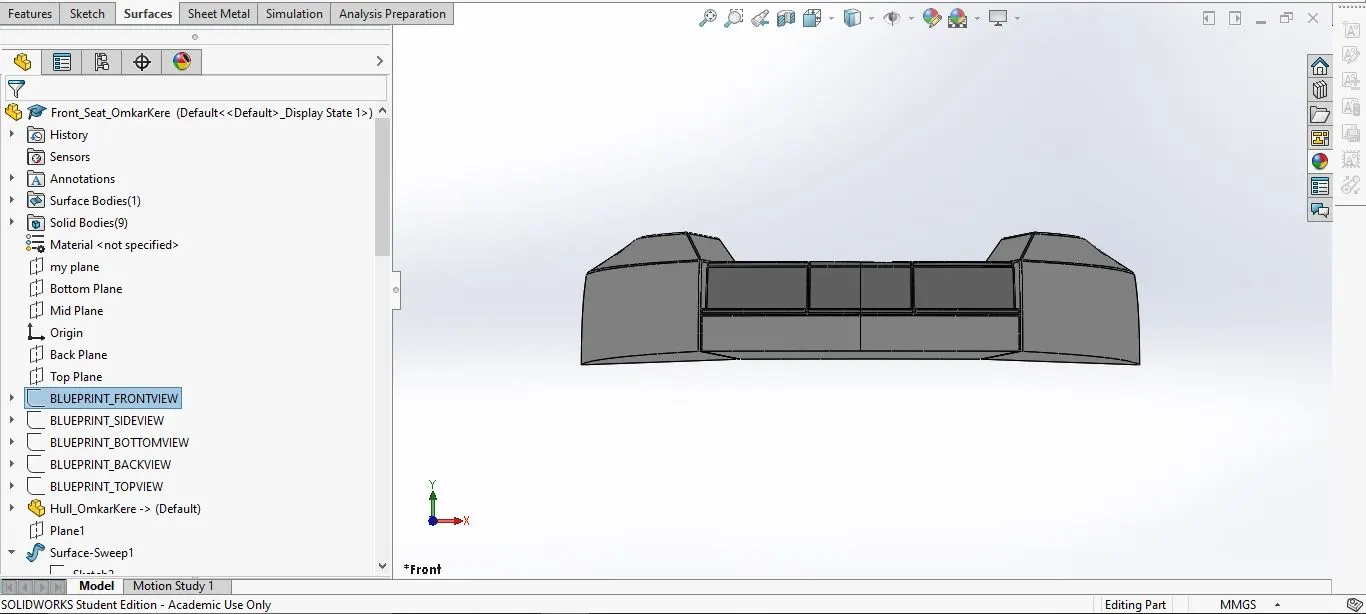
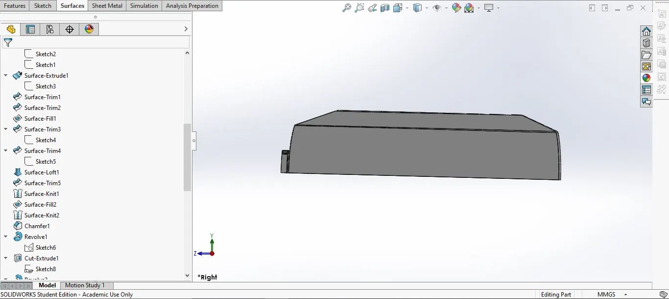
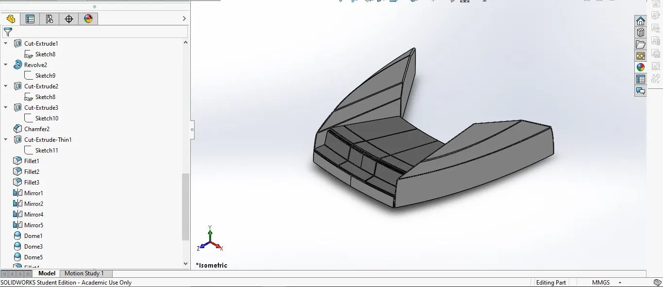
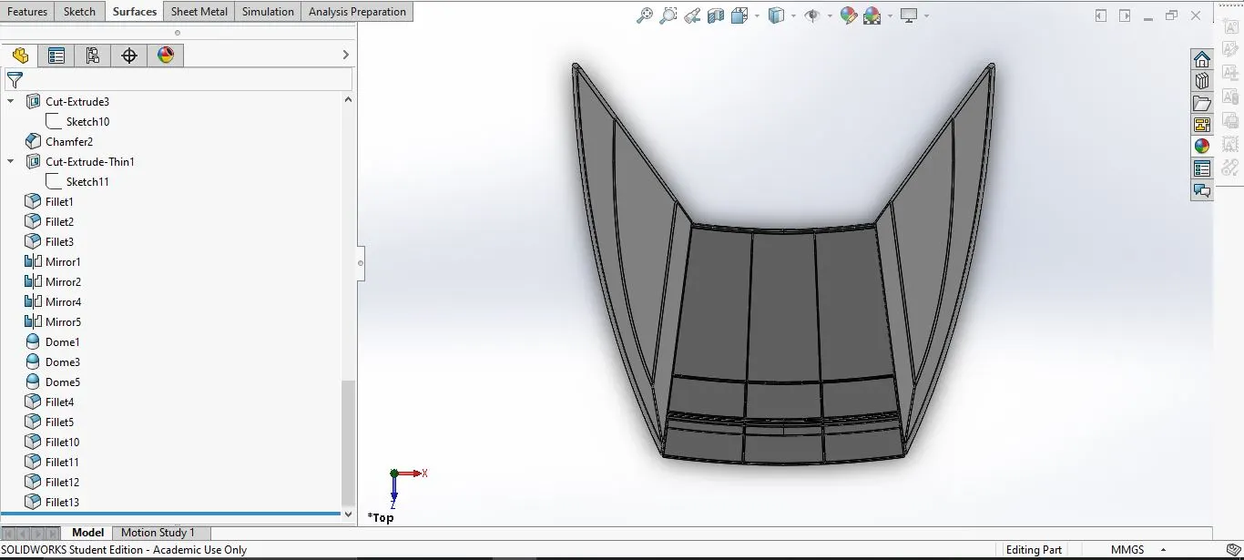
5. Front Seat:
Located in front of the superstructure.
- Tools and features used:
- Plane
- Sweep
- Surface Loft
- Surface Trim
- Extrude Cut
- Revolve
- Surface Knit
- Surface Fill
- Dome
- Mirror
- Fillet
- Chamfer
- Design methodology:
Insert the deck surface from the hull-->using the top and side blueprints start the sketch-->Draw two sketches according to the blueprint-->Use surface options to make the surfaces-->Make the seats-->add fillet and chamfer-->Mirror the seat and make a solid body.
- Part with expanded feature tree:
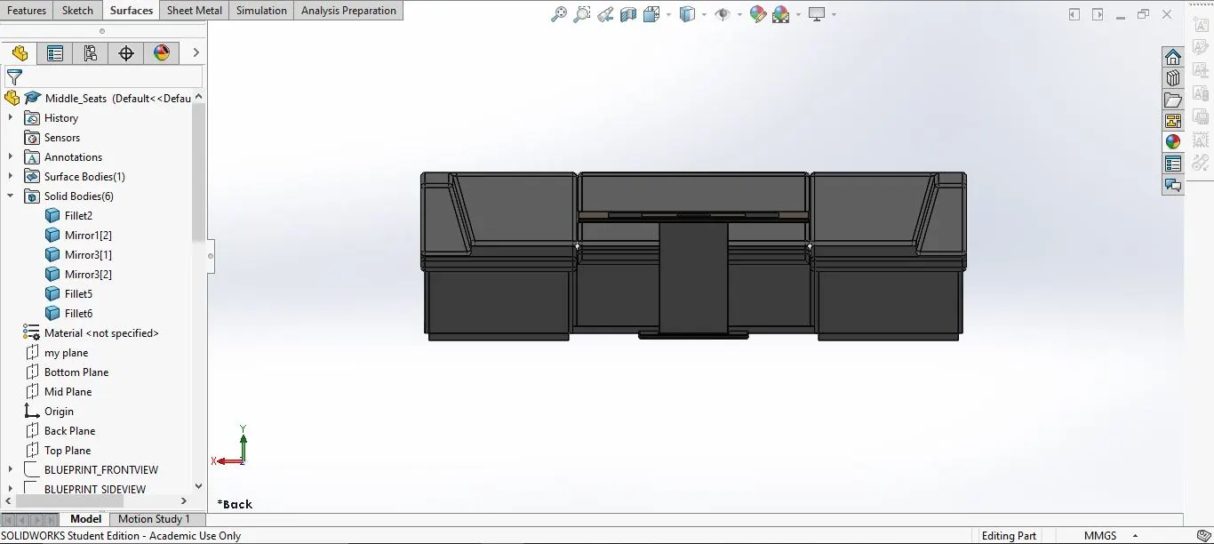
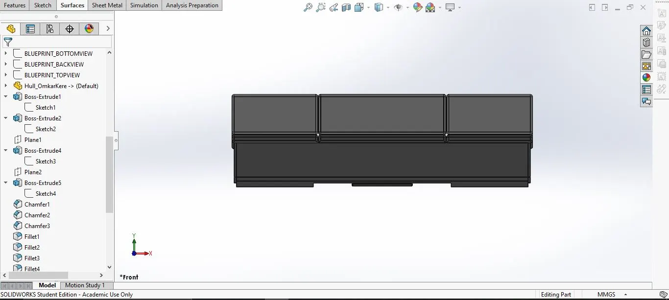
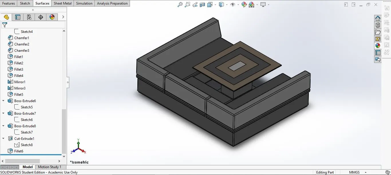
6 Middle Seat:
This is located between superstructure and the rear seat.
- Tools and features used:
- Extrude Bose
- Chamfer
- Fillet
- Mirror
- line
- Rectangle
- Part with expanded feature tree:
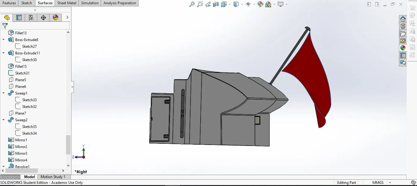
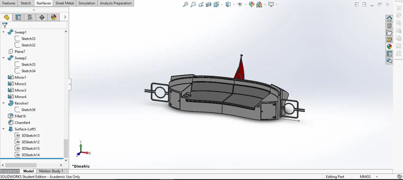
7. Rear Seat:
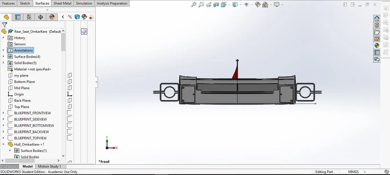
This seat is located at rear end of the yacht.
- Tools and features used:
- Surface loft
- Surface extrude
- Surface Offset
- Surface trim
- Sweep
- Ruled Surface
- Surface Extend
- Surface Knit
- Surface Extend
- Extrude Bose
- Chamfer
- Extrude Cut
- Mirror
- Plane
- Fillet
- Design methodology:
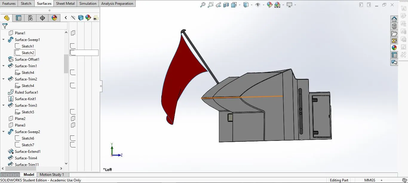
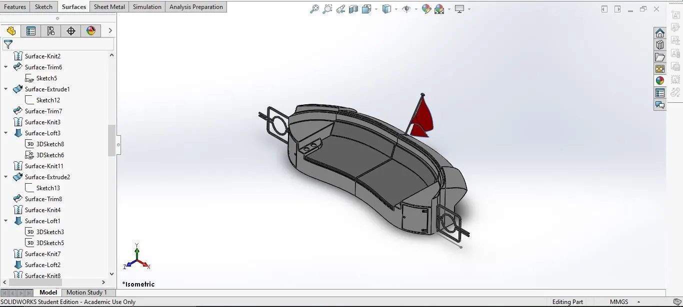
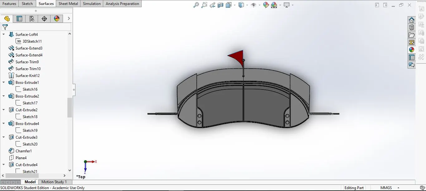
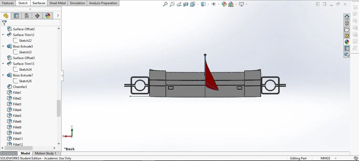
The desig methodology is same for the middle seat as well: Use the top and side blueprints and the hull surface--> MAKE the sketch-->add dimensions-->add fillets and chamfer-->mirror the seat and form the solid body.
- Part with expanded feature tree:
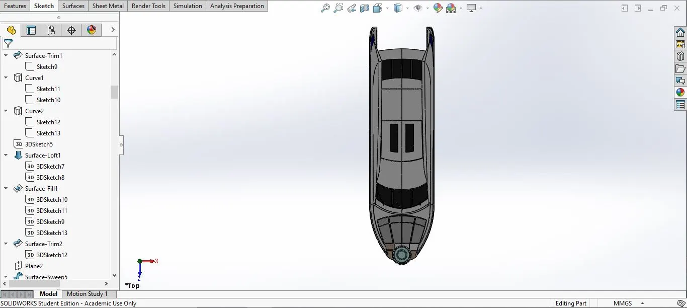
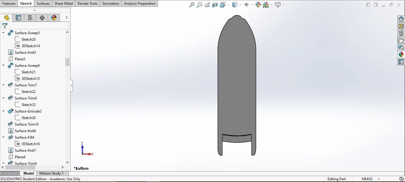
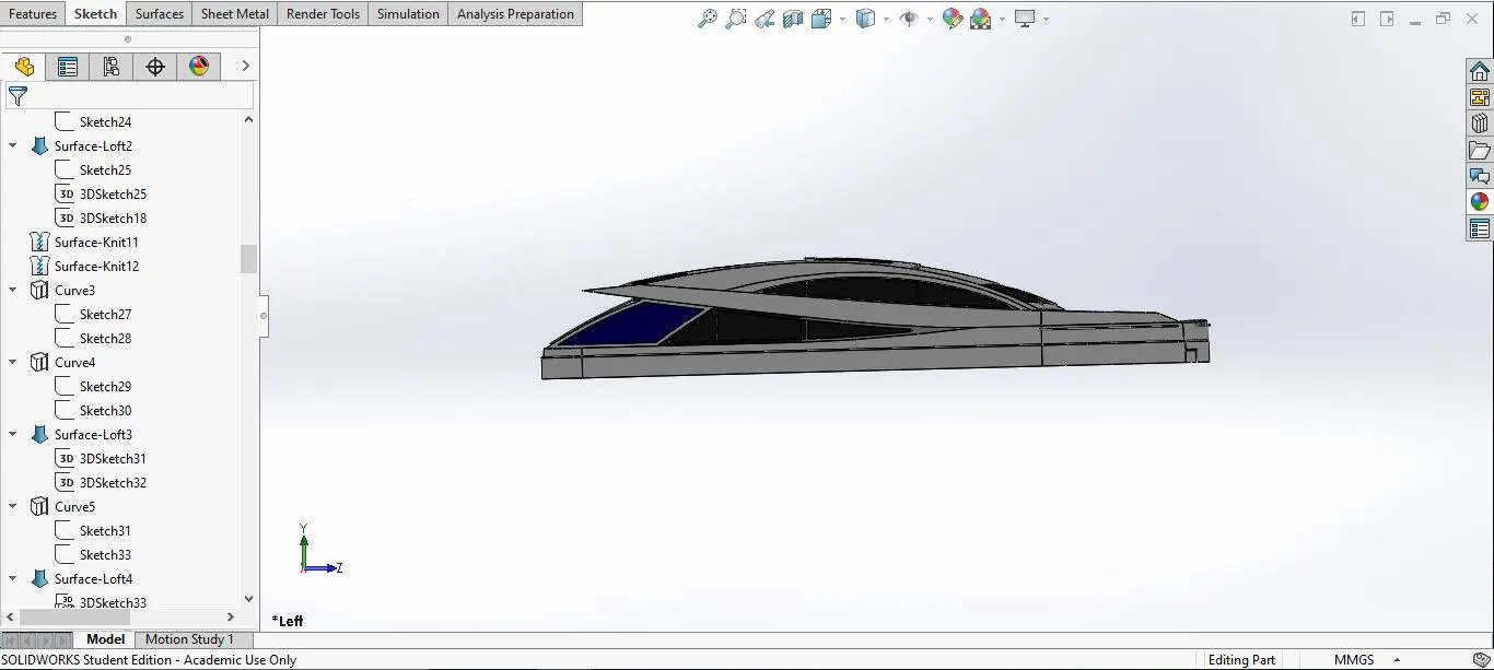
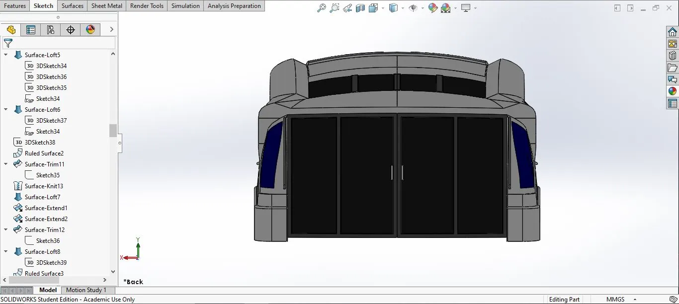
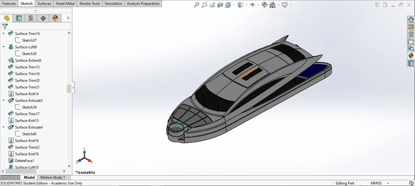
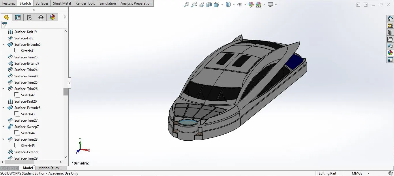
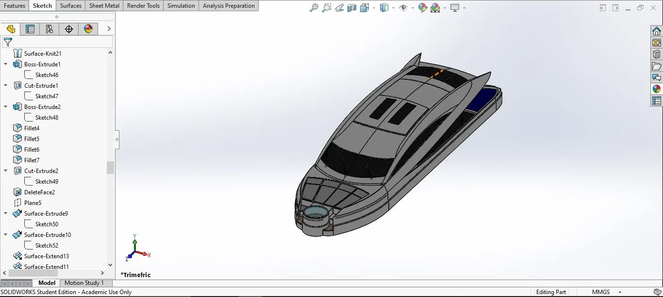
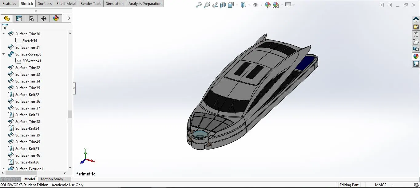
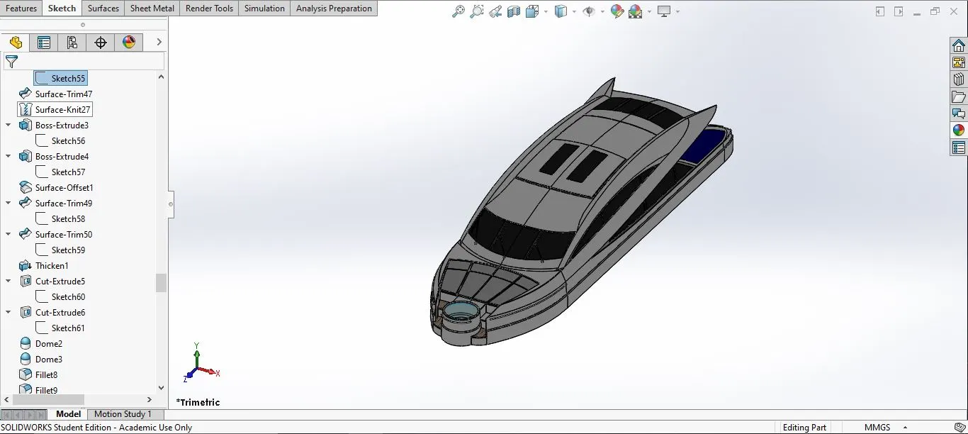
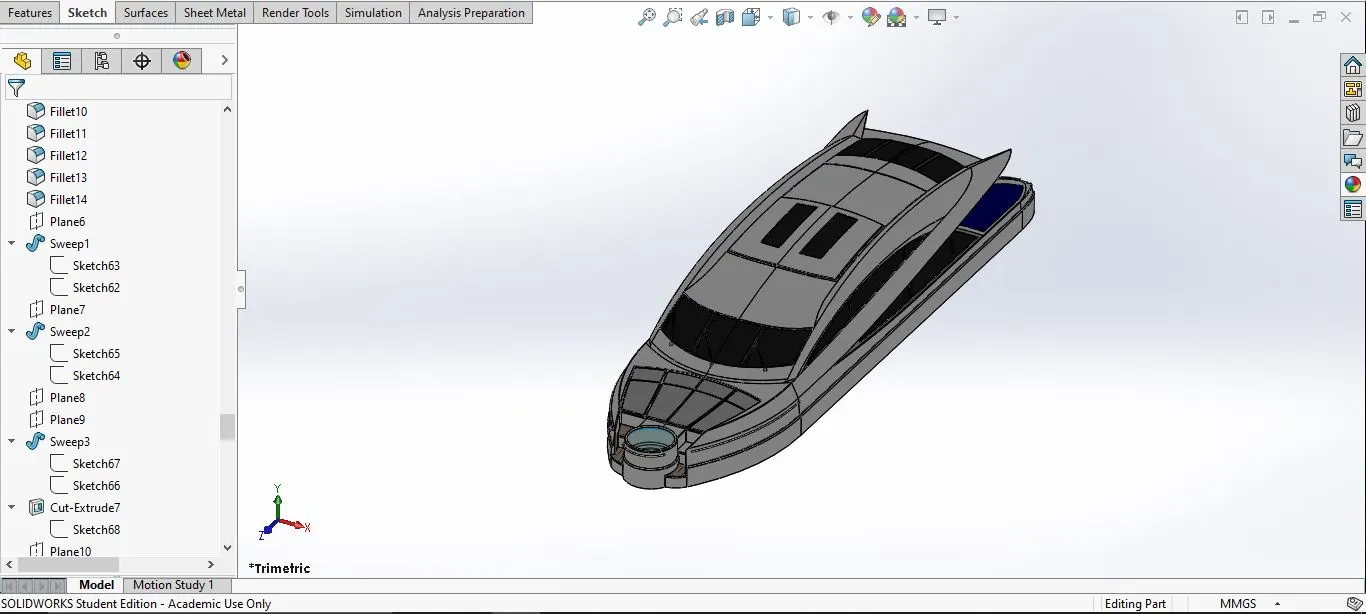
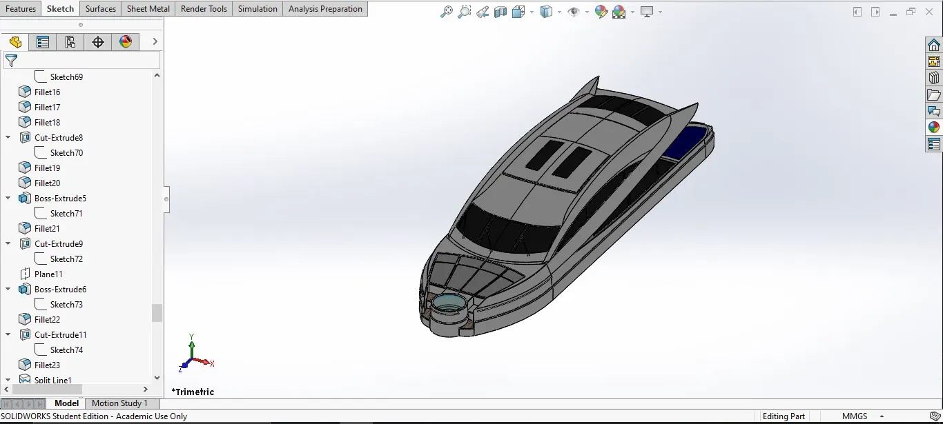
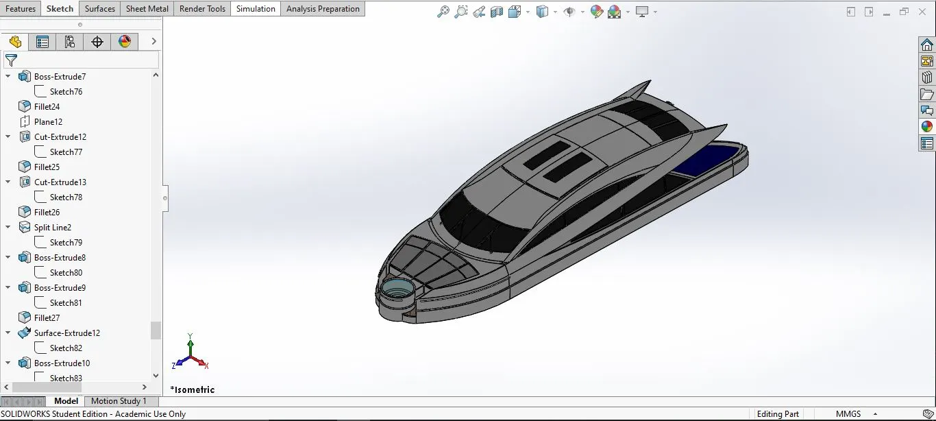
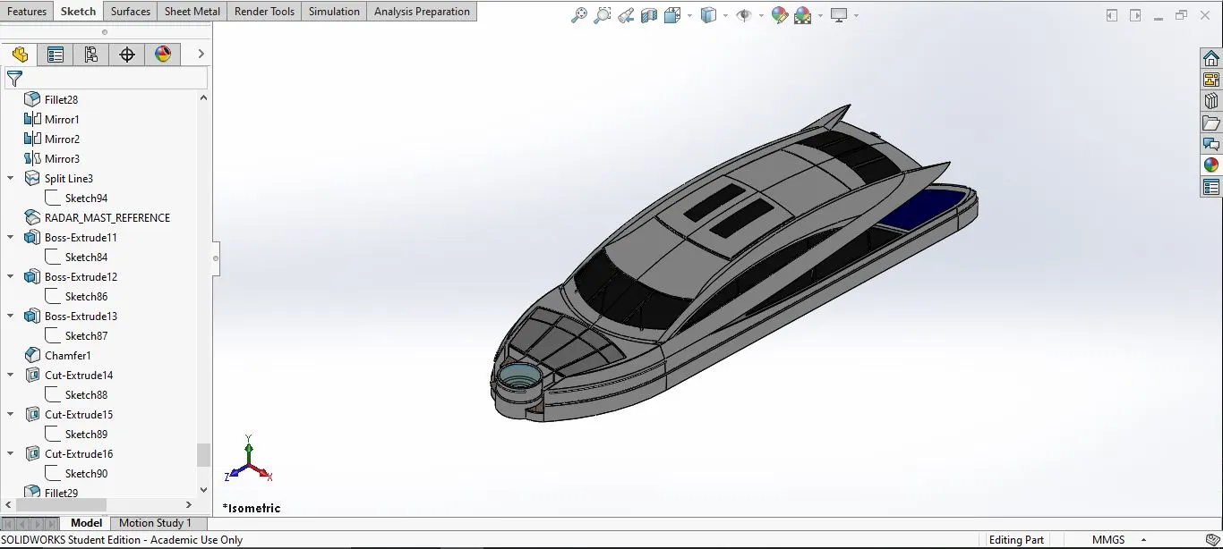
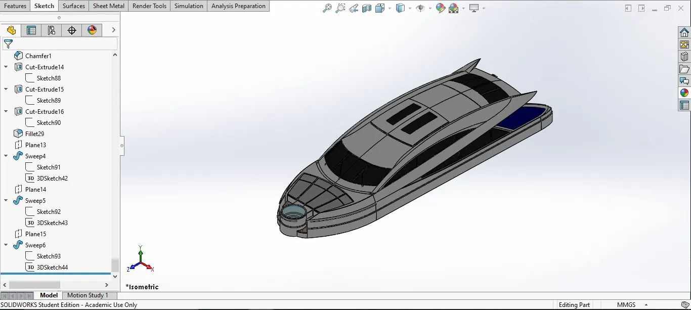
8. Superstructure:
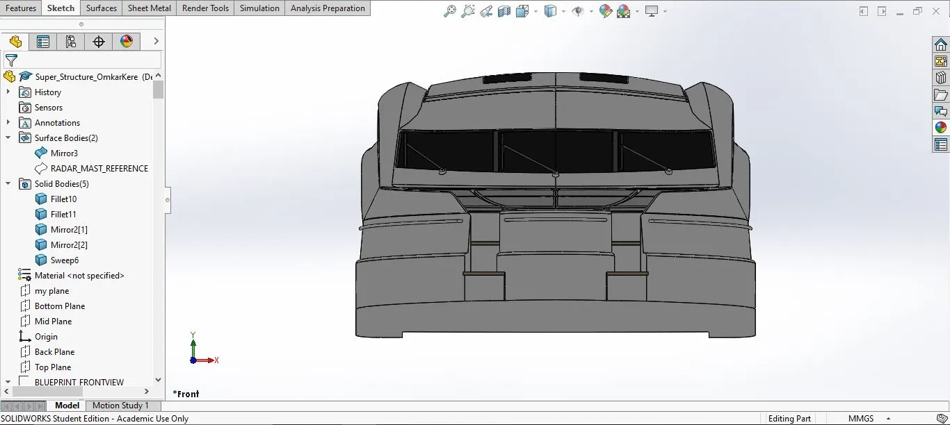
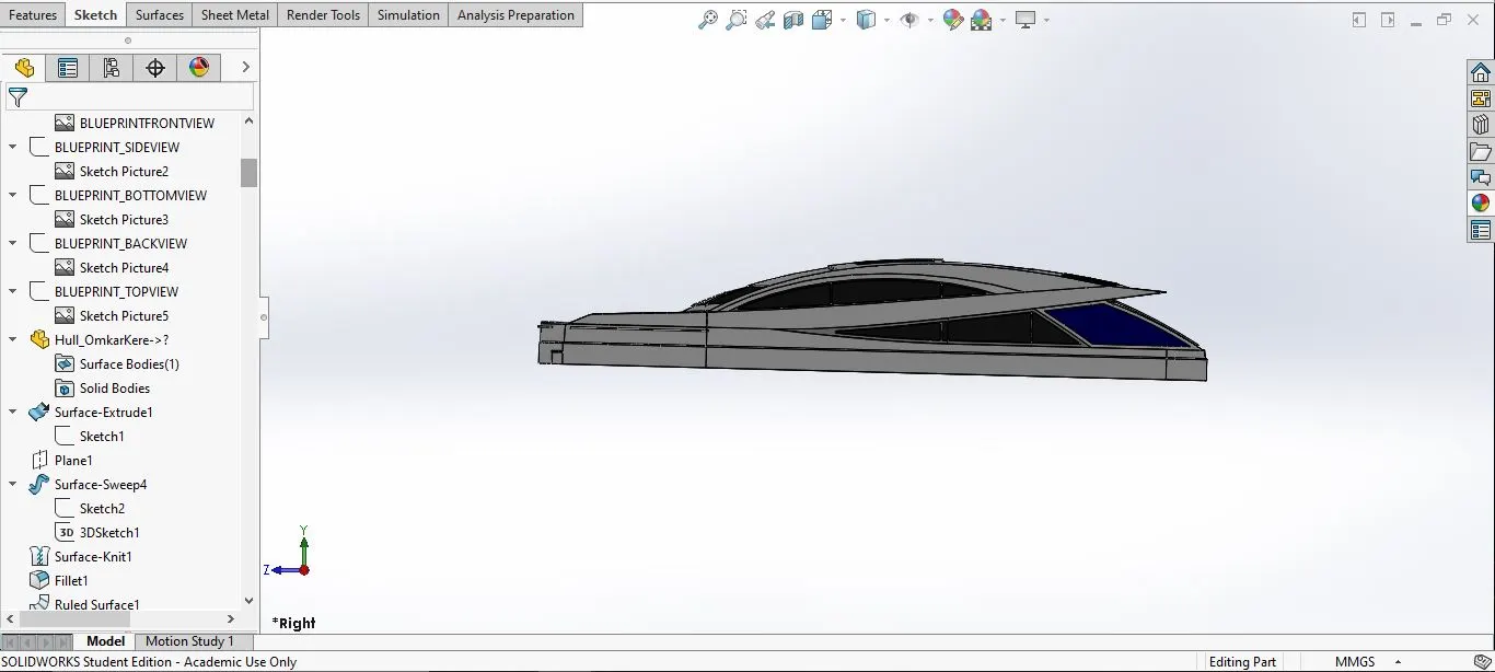
This is the part from where the Yacht is operated.
- Tools and Features used:
- line
- spline
- circle
- extrude cut
- Projected curves
- Offset
- Surface fill
- surface Extrude
- Surface sweep
- Dome
- Surface Trim
- Extend Surface
- Surface Knit
- Plane
- Rulled Surfaces
- Split Entities
- Split Lines
- Delete Faces
- Fillet
- Chamfer
- Mirror
- Part with expanded feature tree:
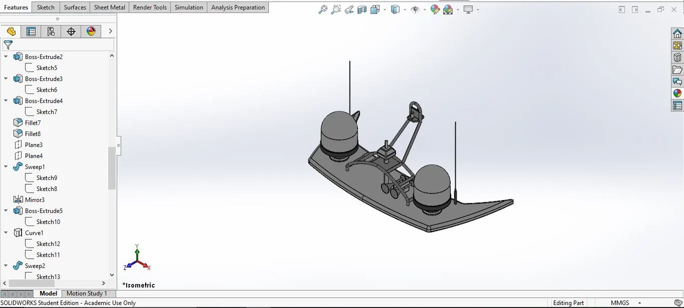
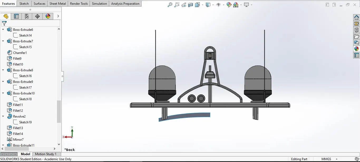
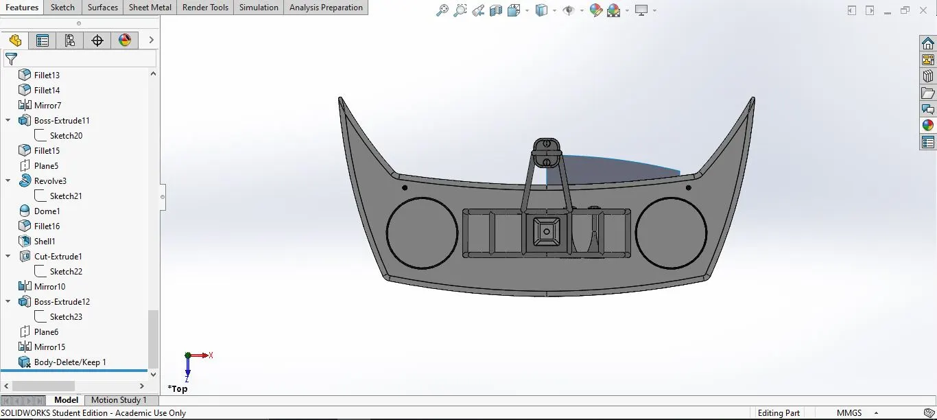
9. Radar Mast:
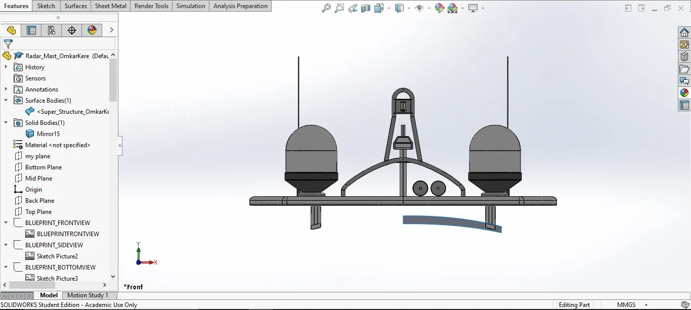
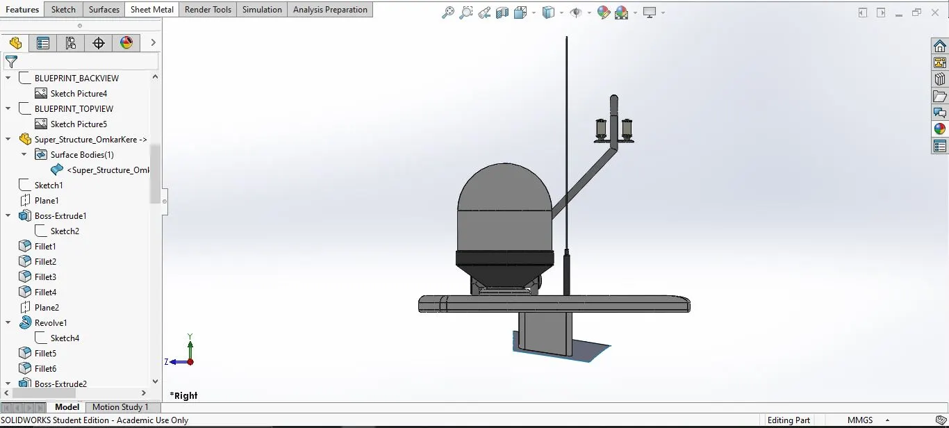
This parts is for communication and GPS.
- Tools and the features used:
- Spline
- Extrude Bose
- Revolve
- Circle
- Mirror
- Line
- Mirror
- Fillet
- Chamfer
- shell
- projected curve
- Design procedure:
Use the superstructure surface and import it in the sketch-->use the side and the top blueprint to make the radar mast-->First make the base of the radar mast and extrude the base-->Then Create the antenas using circle and extrude-->Mkae the support for the radar--> make a profile for the horn and use revolve to amke the horn-->use shell command to make the horn hollow-->mirror the horn-->Make the profile of the two structure and use revolve to create the part-->finally use mirror the entire part except the horn.
- Part with expanded feature tree:
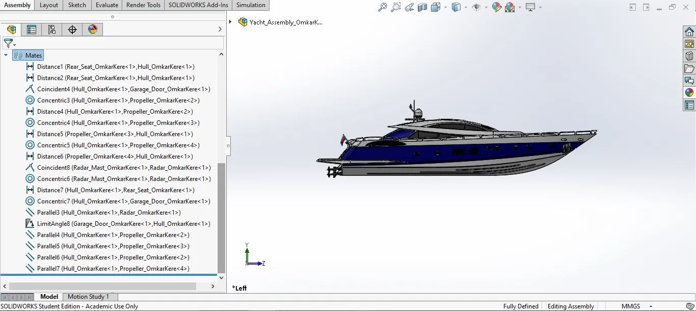
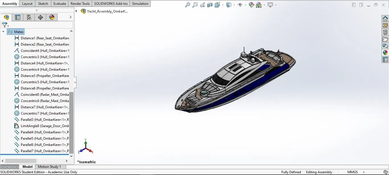
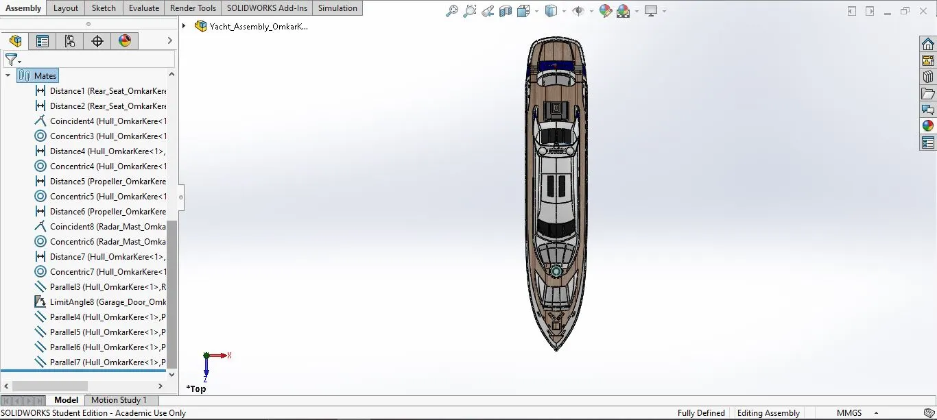
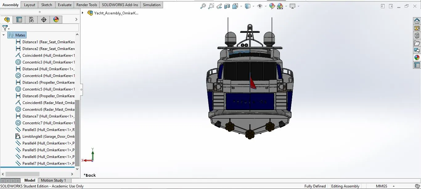
- Assembly of the Yacht:
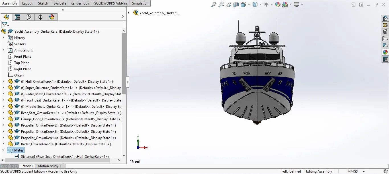
The yacht is assmebled in the SolidWorks assembly space
- Mates used:
- Coindident
- Concentric
- Angle Limit
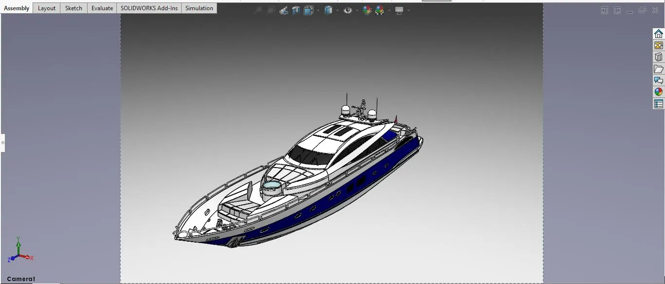
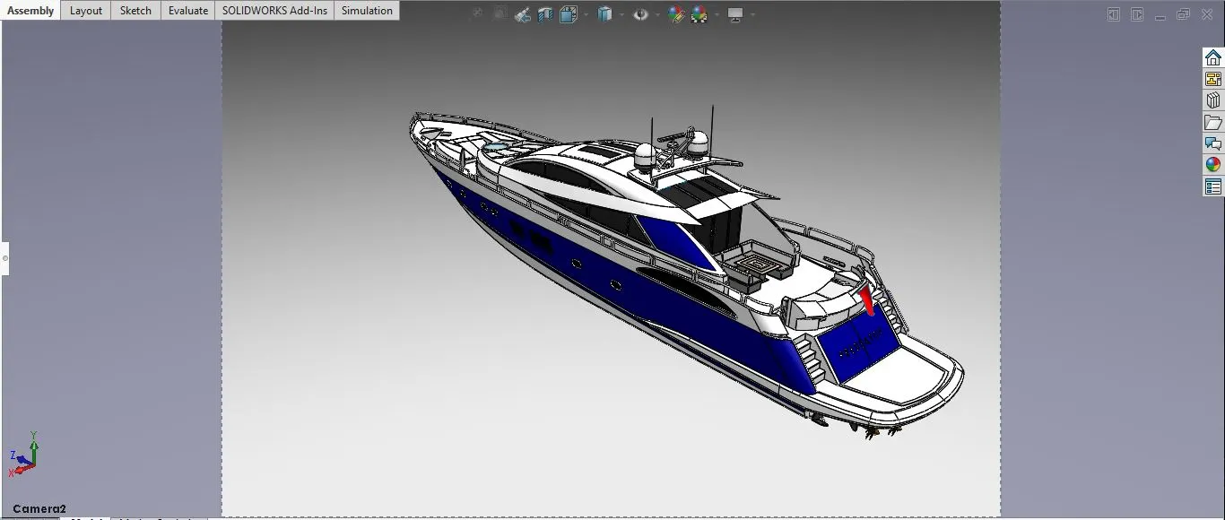
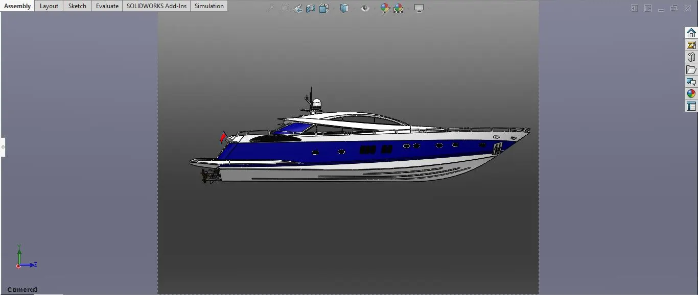
- Camera View:
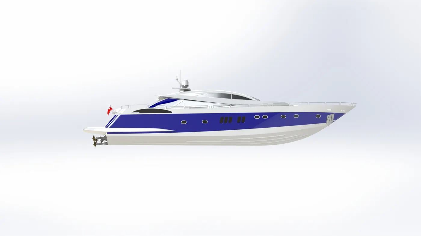
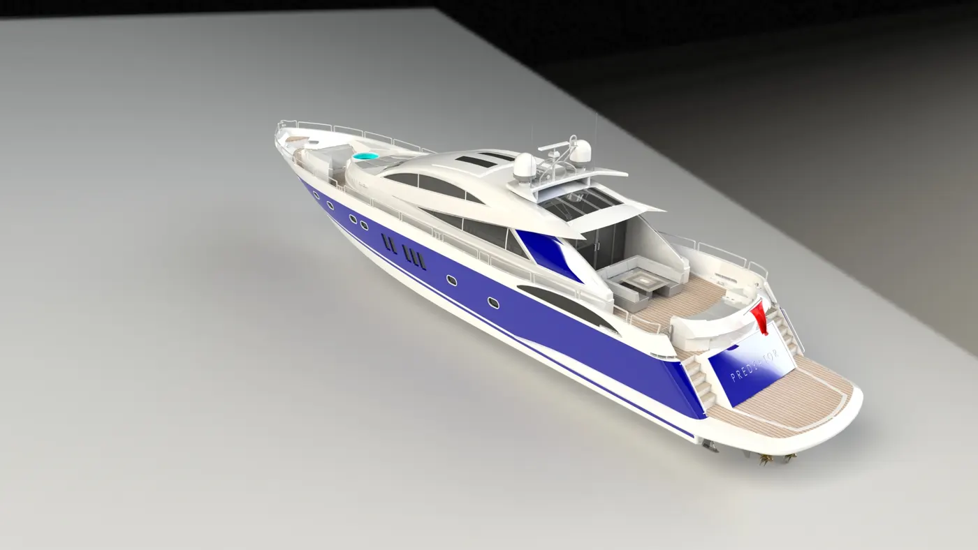
Rendering the Yacht in PhotoView 360
- Conclusion:
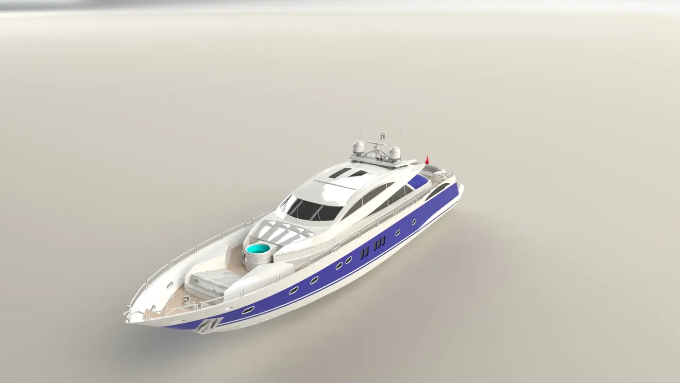
The parts of the Yacht were designed using SolidWorks and then assembled in the assembly window. The assembled Yacht was then rendered using Photoview 360.