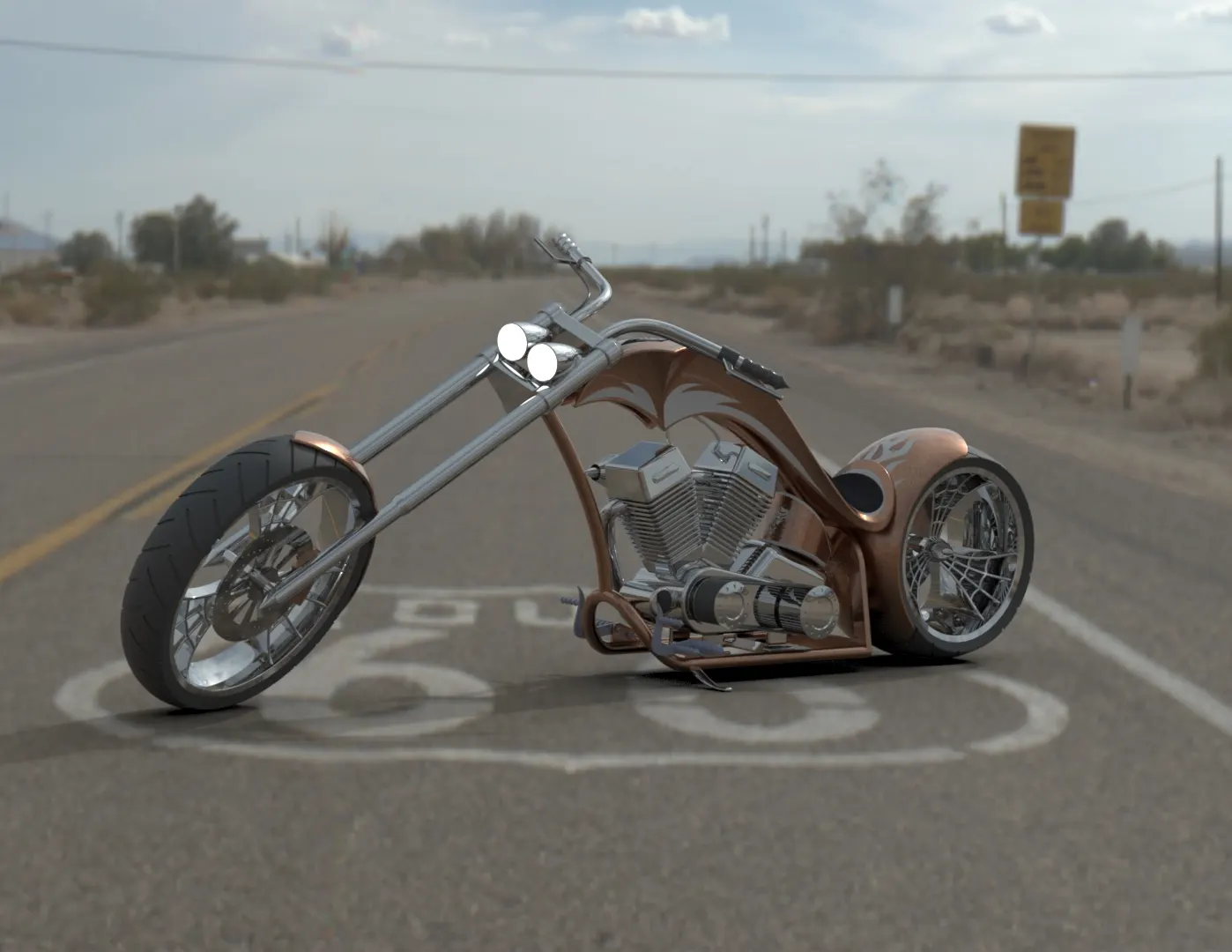
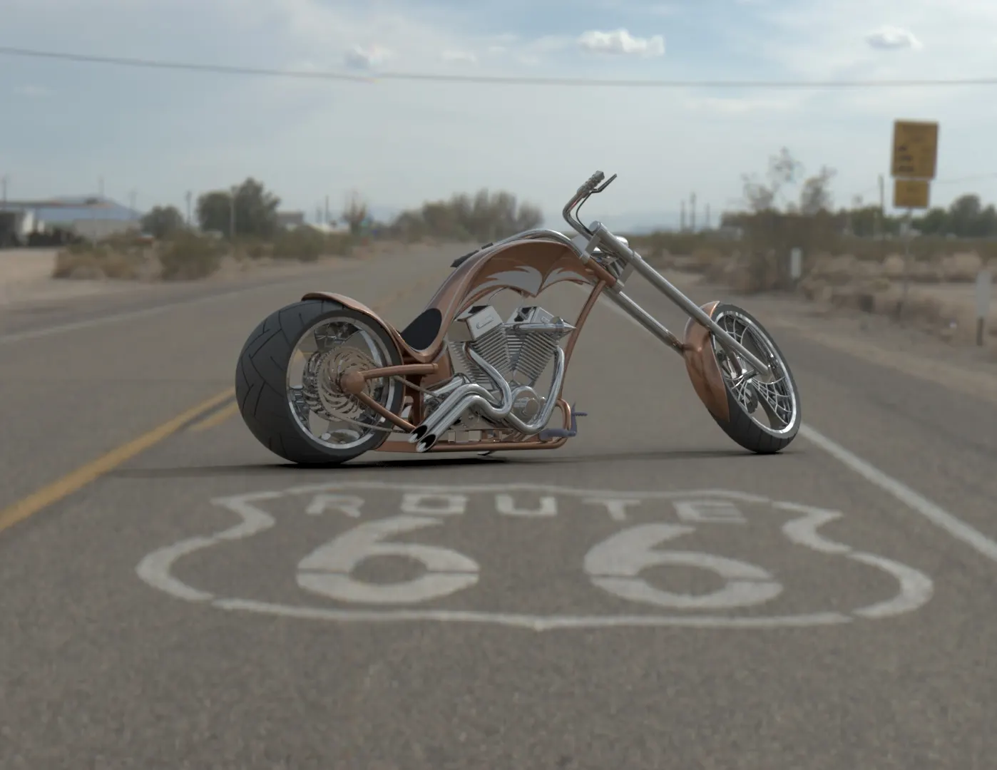
Photo Realistic Rendering
Design, Assembly and Rendering of American Chopper Bike using SolidWorks
Objective:
1.The objective of this project is to design/model the parts of an American chopper bike in SolidWorks software
2. Assemble all the parts in SolidWorks assembly.
2. Render photorealistic images of the chopper using Photoview 360.
3. Render images of the chopper by setting up in the enviorment in SolidWorks Visualise.
Introduction:
SolidWorks is parametric modelling software developed by Dassult System, used for modelling components in automotive, aeronautics and many other industries. Being parametric modeling sofware it is very easy to make configuration to the model in SolidWorks. In this project an American chopper bike is designed using parametric modelling in solid works. The designed parts are then assembled in assembly of the SolidWorks. The assembled bike is then rendered using Photoview 360 and SolidWorks Visualise. Photoview 360 is an add-in built in SolidWorks which can make high quality renders. The SolidWorks Visualise is a software to make render by placing objects in an enviorments.
- Design and modeling of parts using SolidWorks:
- Tools and Features used:
- Circle: This command is used to create circles in solid works
- Line: This command is use to create line in solid works. It can be normal line or construction or midpoint
- Rectangle: This command is use to create rectangle in SolidWorks.
- Arc: This feature is used to make an arc.
- Spline: This feature is used to make a line whose curvature can be adjusted.
- Extrude Bose: This feature is used to make a 2D sketch into a solid body.
- Extrude Cut: This feature is used to cut through a solid body.
- Revolve Bose: This feature is used to create a solid body from sketch around an axis.
- Revolve cut: This feature is used to create a cut in solid body around a revolve axis.
- Swept: This command is used to make a solid body which follows a particular axis; this axis is known as swept axis. This command is used for making uneven solid bodies.
- Swept cut: This is used to make cut along a swept axis in a solid body.
- Shell: This is used to make a solid body hollow.
- Split: This feature is used to cut two different bodies.
- Linear Pattern: Used for making linear patterns for solid bodies or cuts along a reference line.
- Circular Patttern: Used for making circular pattern of solid bodies or cuts along a reference axis of a circular reference geometry.
- Fillet: This is used to make a rounded faces internall or externally on the edges of the body or sketch.
- Chamfer: used for making inclined faces on the edges og the solid body.
- Mirror Entites: This feature is used to make a copy of the sketch along a reference plane/axis/line.
- Curve Driven Pattern: This feature is used to make a pattern of solid bodies or cuts along an uneven curve.
- Mirror: This is used to make copy of the solid body along a reference plane/axis/line.
- Reference geometry: This is used for creating reference planes, axis, etc.
- Projected curves: This is used to make uneven or curves which follow certain path using two or more reference curves.
- Dome: This feature is used to create a dome like solid body.
- Sketch Image: This is used to insert an image which is used for reference while creating the part.
- Loft: This is used to add material between two or more profiles to make solid bodies.
- Surfae features used:
- Extruded Surface: To make a surface from a line.
- Revolve Surfce: To amke a revolved surface.
- Swept Surface: To make sweep on uneven lines or curves.
- Lofted Surface: To make surface lofts.
- Boundry Surface: To make surfaces from the boundry.
- Relations used for modeling:
- Coincident: This relation makes two points of two line or a point and line coincident with each other.
- Concentric: This relation make two circle or a point and a circle concetric.
- Parallel: This makes two lines parallel to each other.
- Perpendicular: This makes the two lines perpendicular.
- Equal: For making lines, circles equal to each other.
- Tangent: To make lines and arc tangent.
- Make Pierce: To attach the center point of and elipse or circle to the line
- Horizontal: This relation makes lines horizontal to origin. This is also used for making two points or point and a line horizontal.
- Vertical: This is used to make lines vertical with respect to the origin
- Changing appearences:
The appearence of the parts can be changed while modeling the part. In feature tree go to the appearence tab and select appearence. We can apply any appearence.
- Parts modeled:
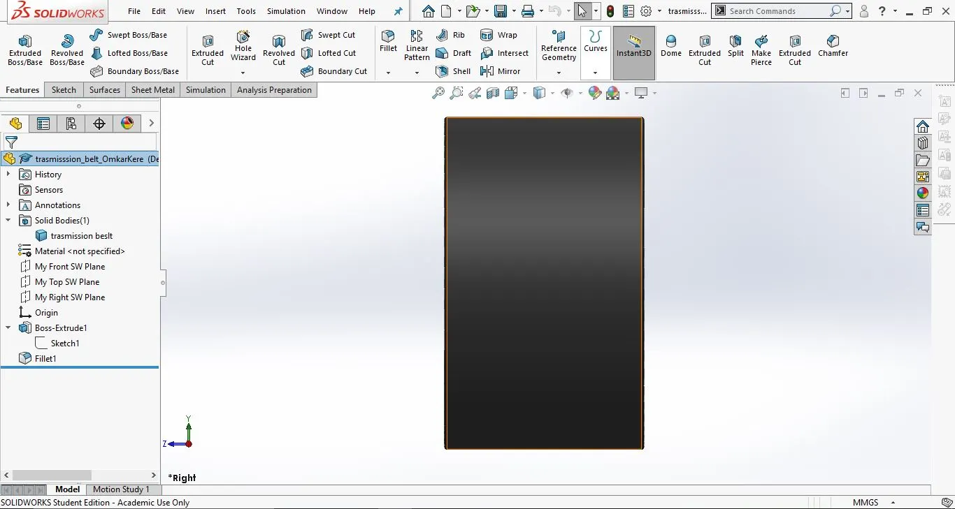
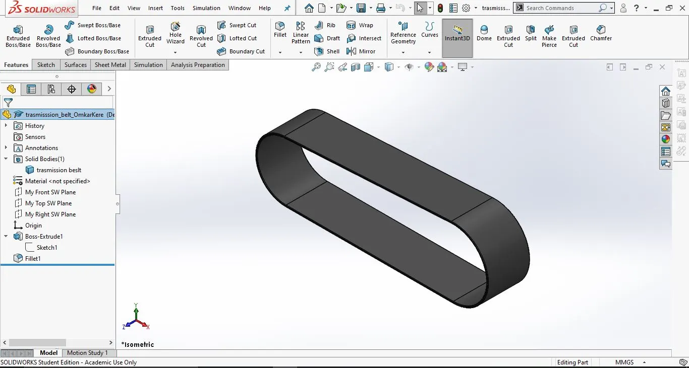
- Transmission Belt:
A transmission belt is used for transmitting power from the piston to the clutch of the bike.
- Tools and Features used:
- Circle: This feature is used to create circle in SolidWorks
- Line: This feature is used to create line. It can be a construction line
- Trim: This feature is used to remove extra sketch or the sketch which is not required.
- Offset: This feature is use to create same sketch at a given distance.
- Extrude: This feature is used to make a 2D sketch into a 3D sketch.
- Fillet: This feature used to make round corners and edges.
- Appearence: Matte rubber.
- Part images with Feature tree:
- Front View:
 2. Side View:
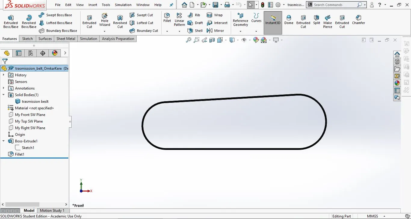
3. Isometric View:
2. Front Fender:
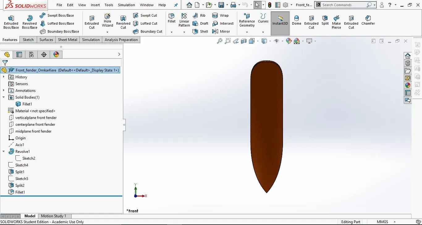
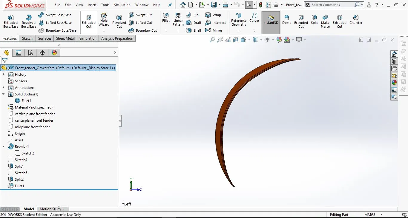
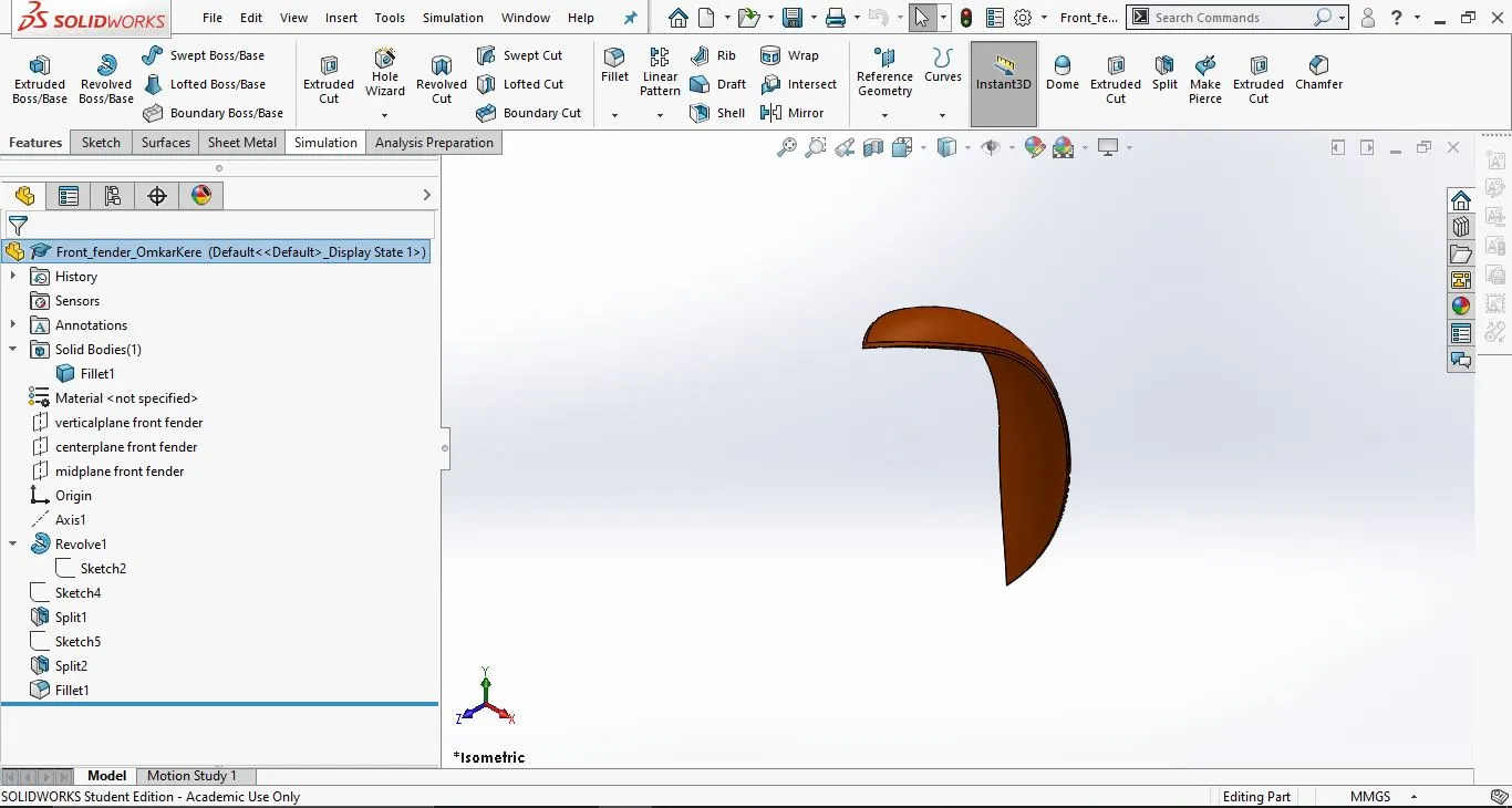
This is the part which is placed above the front wheel
- Tools and features used:
- 3-point arc
- trim/ extend
- Revolve
- split
- Fillet
- Part images with Feature tree:
- Front view:-
2. Side View:
3. Isometric view:
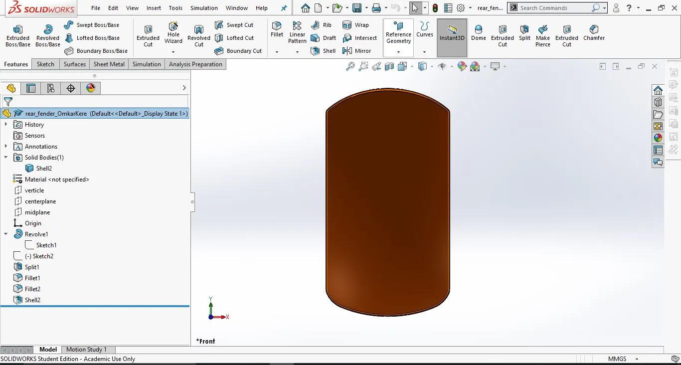
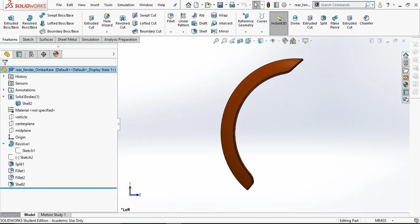
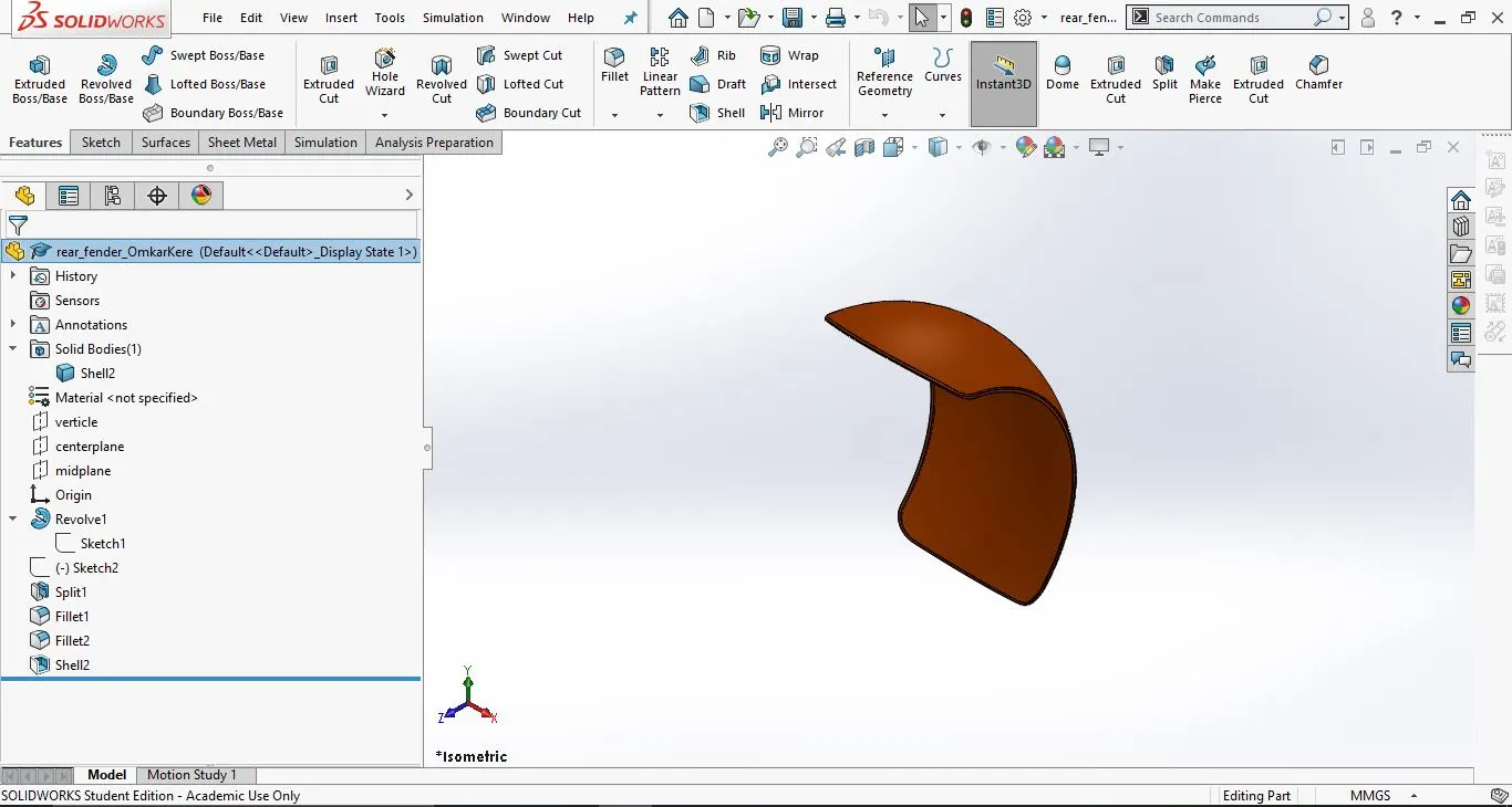
3. Rear Fender:
This is the part which is place above the rear wheel
- Tools and Features used:
- Sketch
- 3-point arc
- Trim/Extend
- Revolve
- Shell
- Fillet
- Part images with feature tree:
- Front view:
2. Side view:
3. Isometric view:
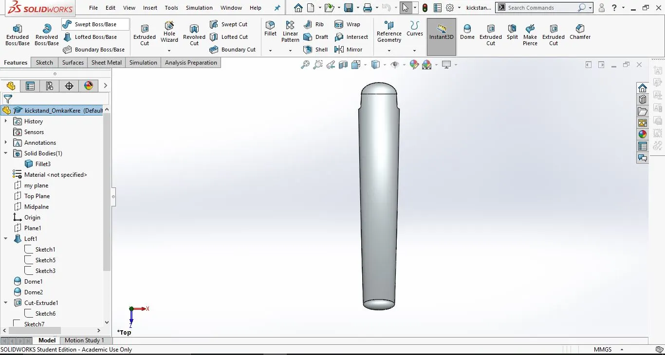
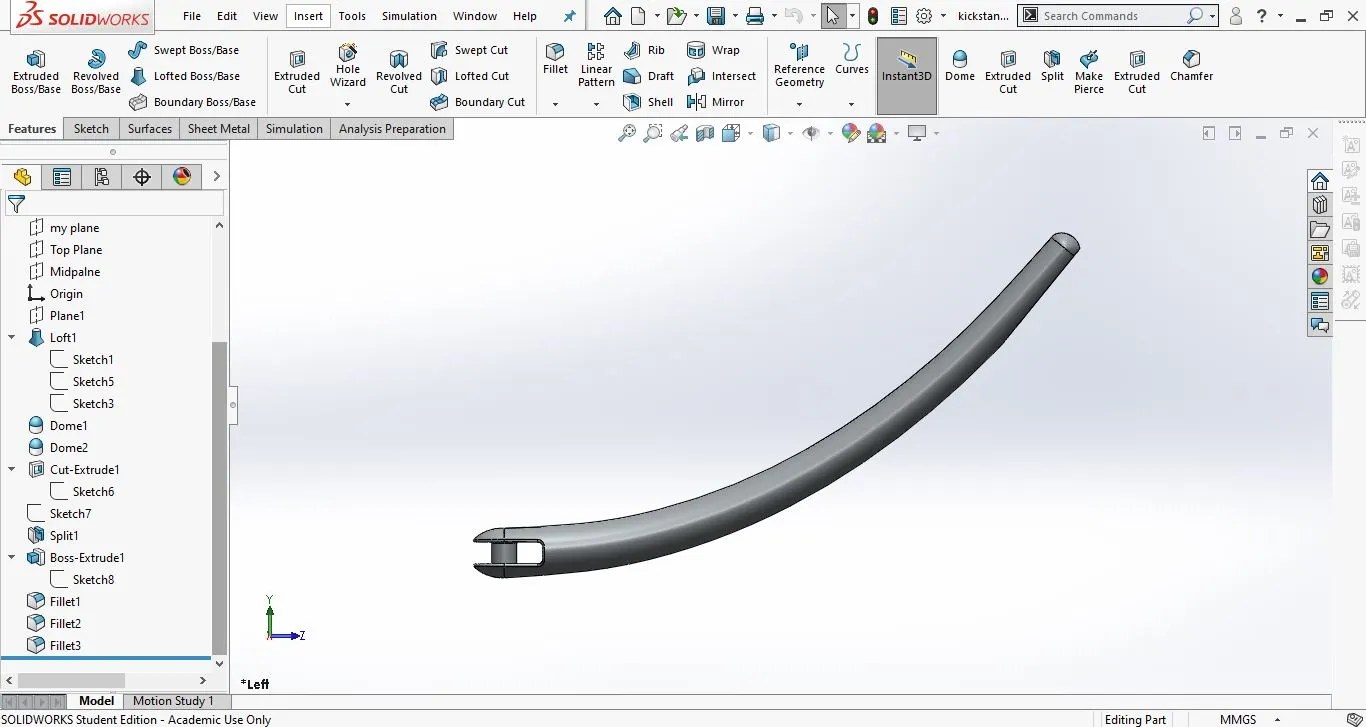
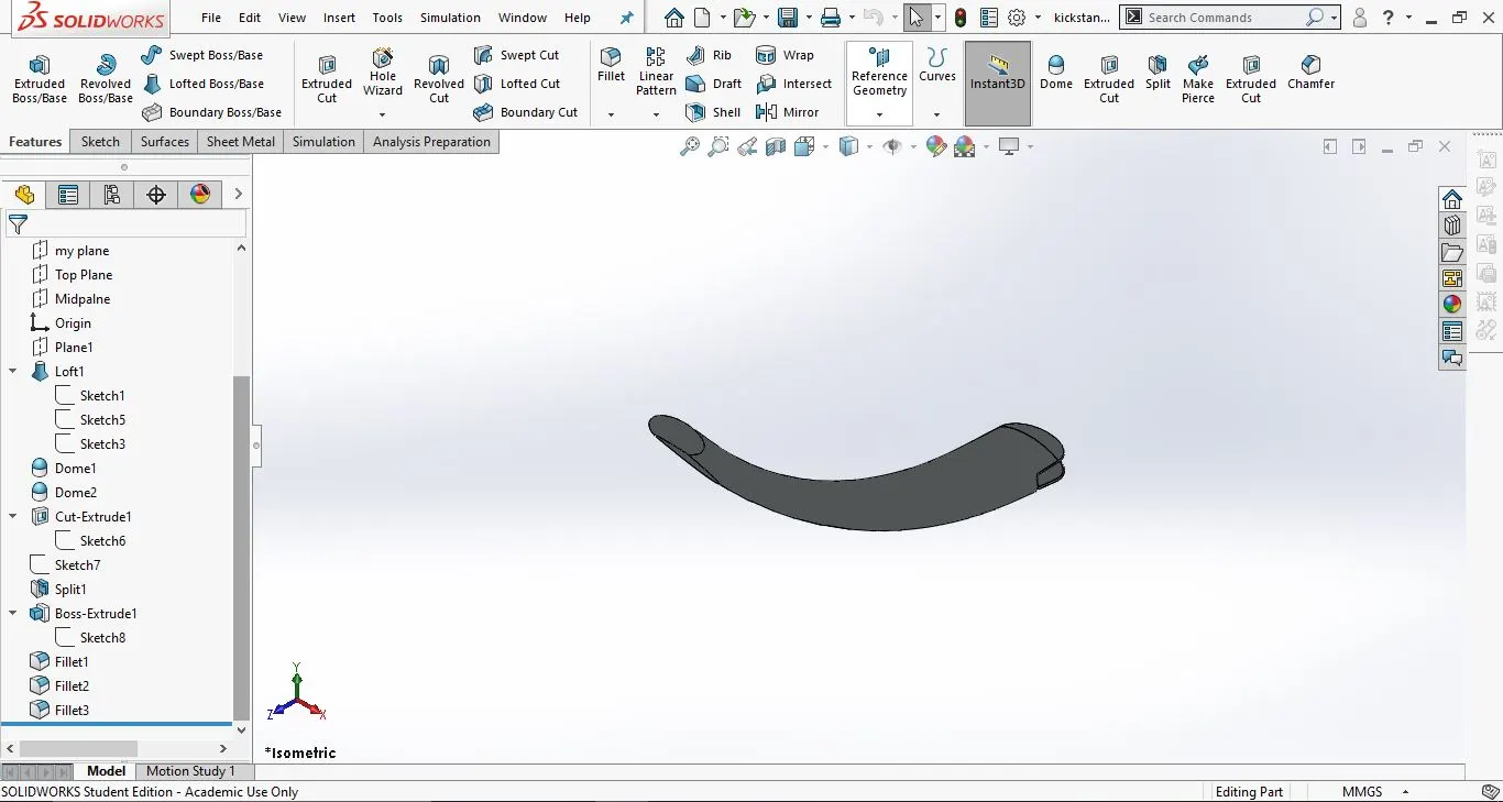
4. Kick stand:
This is the support for the bike to remain standing when the bike is parked.
- Tools and features used:
- Sketch
- Plane
- Ellipse
- Loft
- Dome
- Extrude cut
- Extrude Bose
- Split
- Fillet
- Part images with feature tree:
- Front view:
2. Side view:
3. Isometric view:
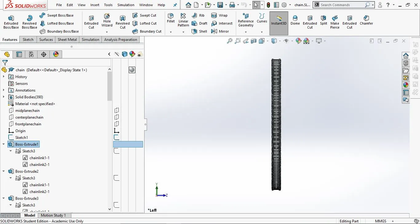
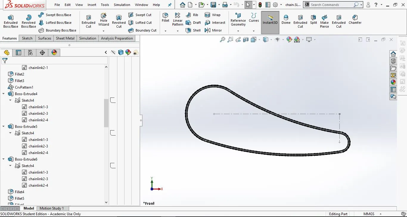
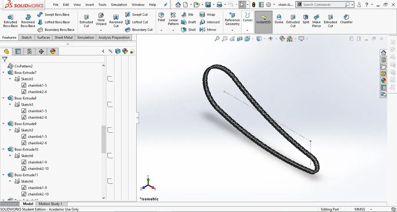
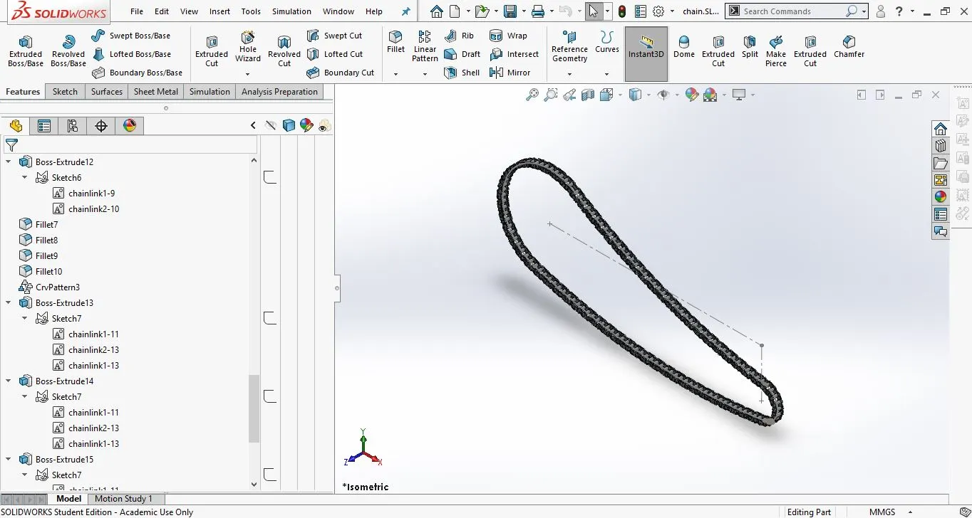
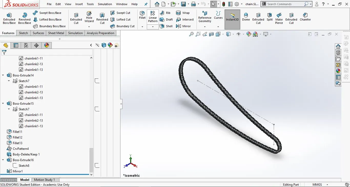
5. Chain:
This is used to transfer power from the gear box (Engine) to the rear wheel
- Tools and features used:
- Sketch
- Line (construction)
- Smart dimension
- Circle
- Slot
- 3-point arc
- Trim
- Block
- Curve driven pattern
- Fillet
- Mirror
- Part images with feature tree:
- Front view:
2. Side view:
3. Isometric view:
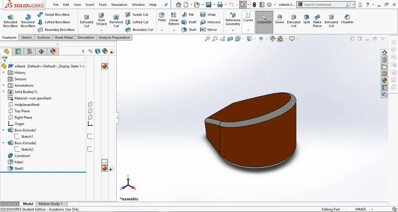
6. Oil tank:
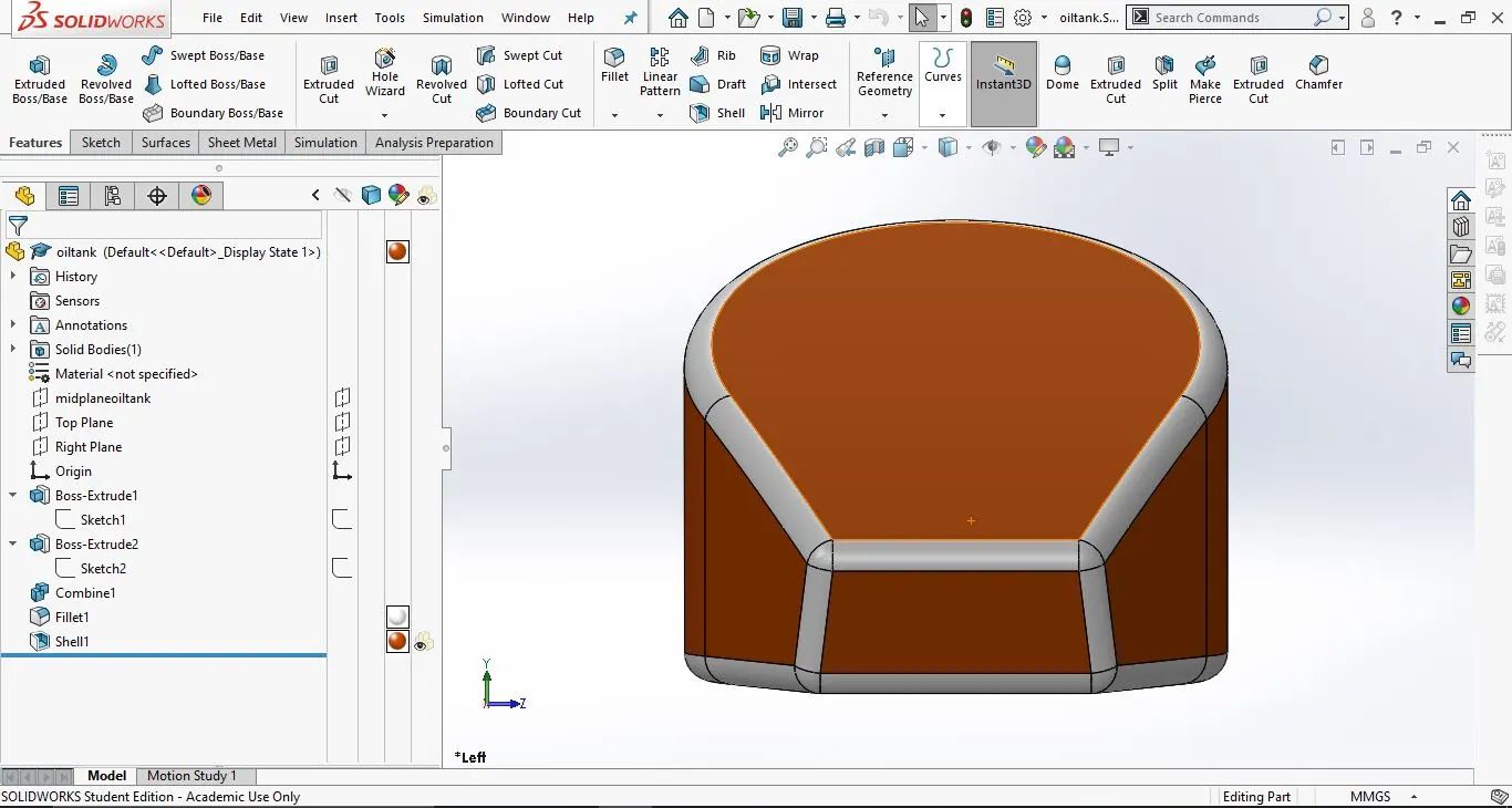
- Tools and features used:
- Sketch
- 3-point arc
- line
- Extrude
- Combine
- Fillet
- Part images with feature tree:
- Front view:
2. Side view: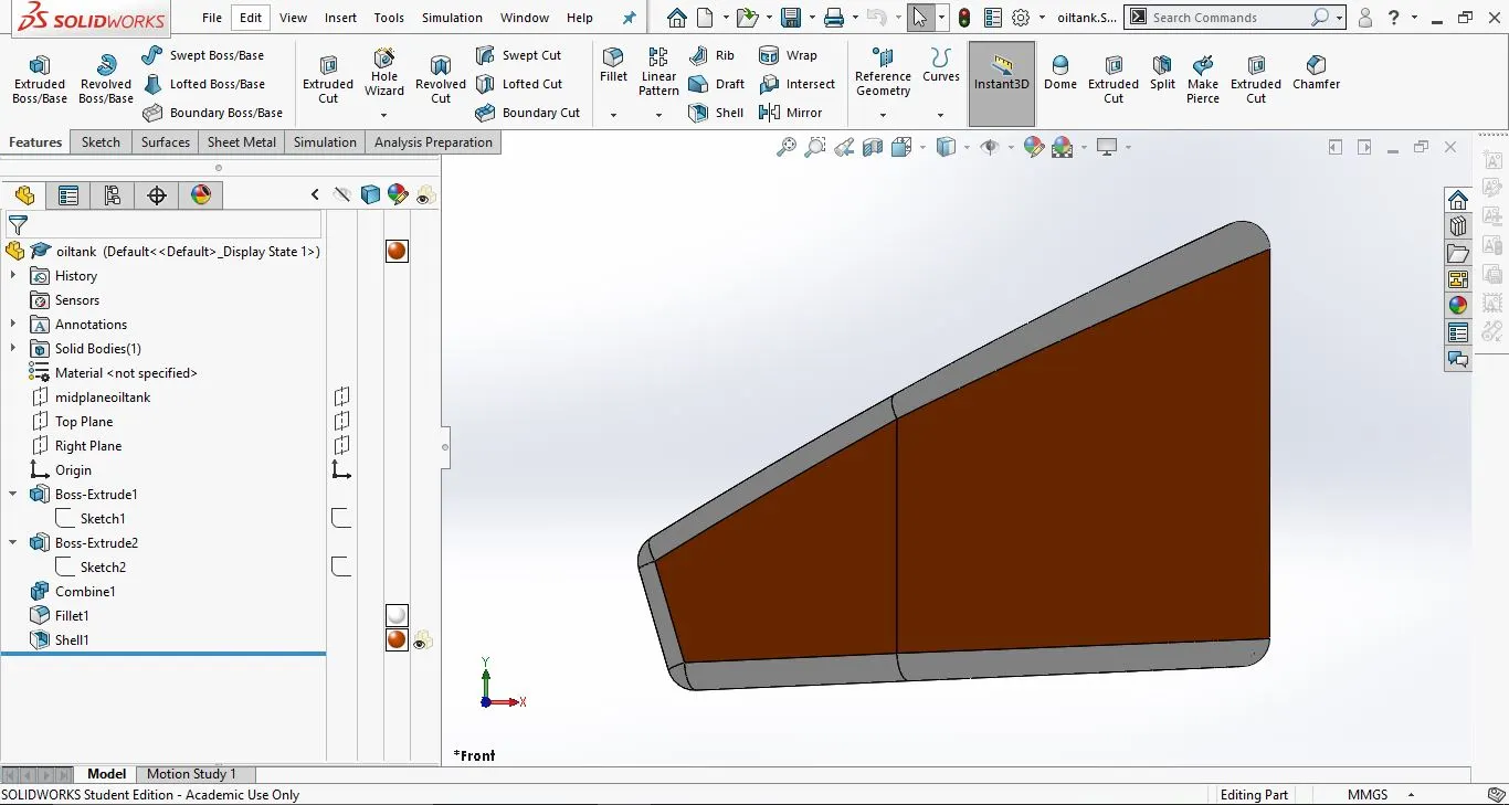
3. Isometric view:
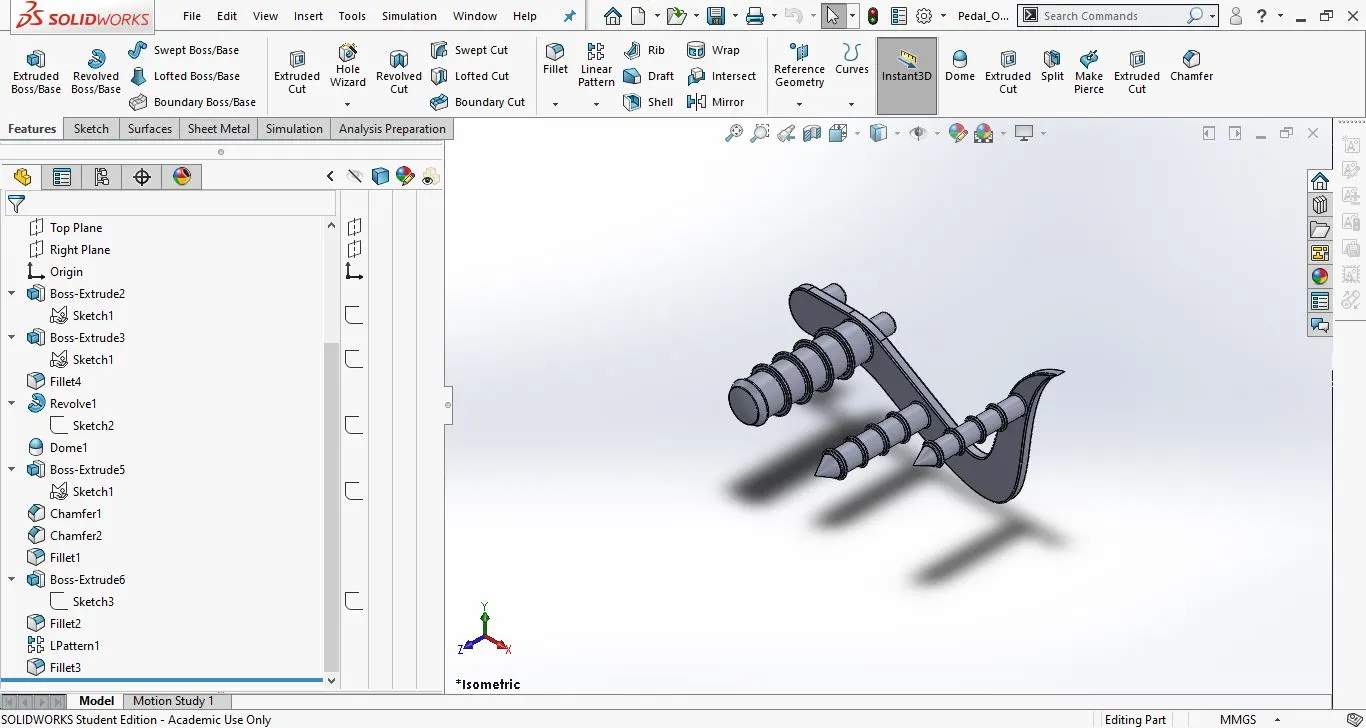
7. Pedal
This part is used for giving support to the riders legs.
- Tools and features used:
- Sketch
- Spline
- Circle
- dome
- revolve
- Line
- Extrude
- Linear Pattern
- Chamfer
- Fillet
- Part images with feature tree:
- Front view:
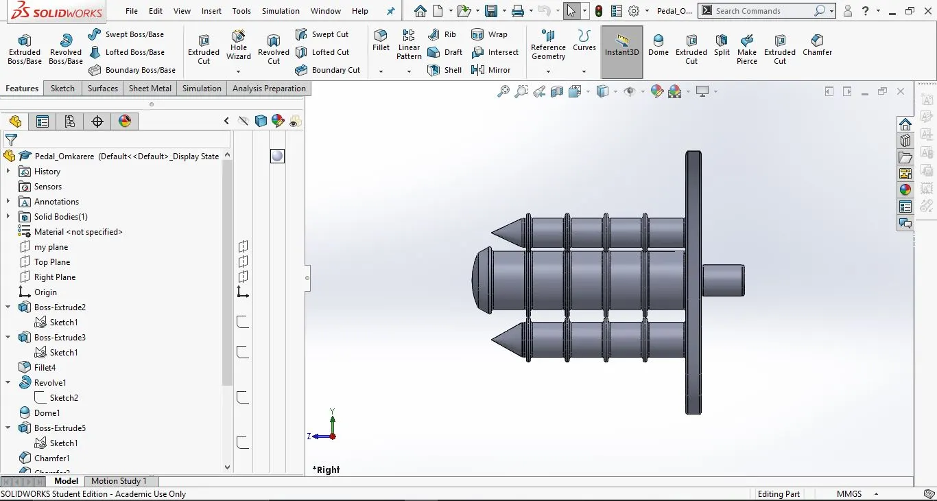
2. Side view;
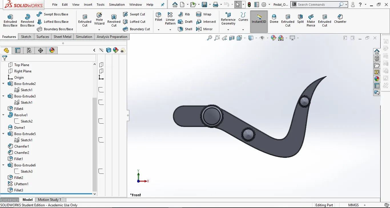
3. Isometric view:
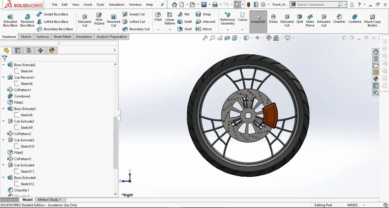
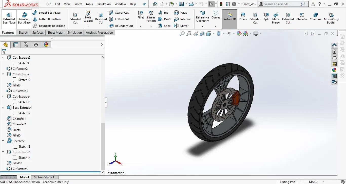
8. Front wheel:
This is the front wheel of the bike
- Tools and features used:
- Sketch
- line
- 3-Point arc
- Revolve
- Offset
- Trim
- Extrude bose
- Extrude cut
- chamfer
- Fillet
- Circular Pattern
- Part images with feature tree:
- Front View:
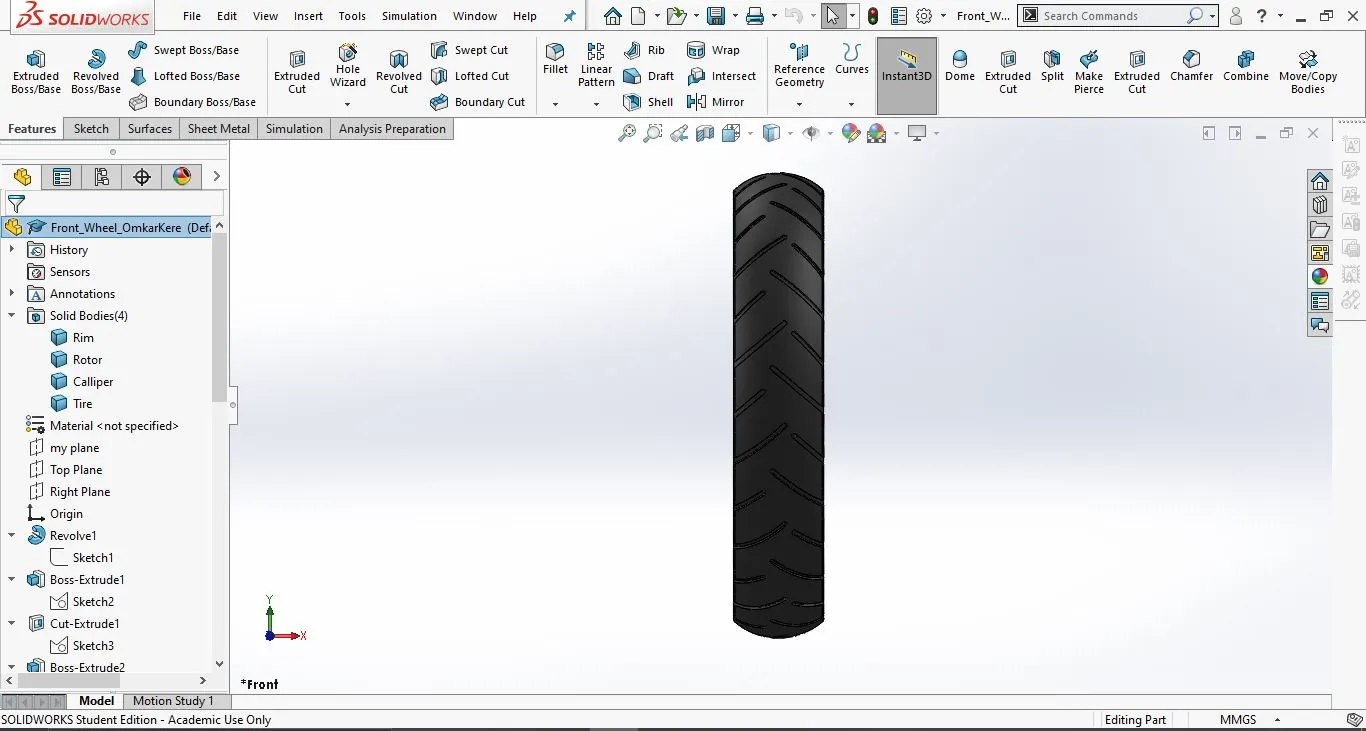
2. Side view:
3. Isometric view:
9. Rear wheel:
This is the rear wheel of the bike.
- Tools and features used:
- Sketch
- line
- 3-Point arc
- Revolve
- Extrude Bose
- Trim
- chamfer
- Offset
- Extrude Cut
- Circular Pattern
- Part images with feature tree:
- Front view:
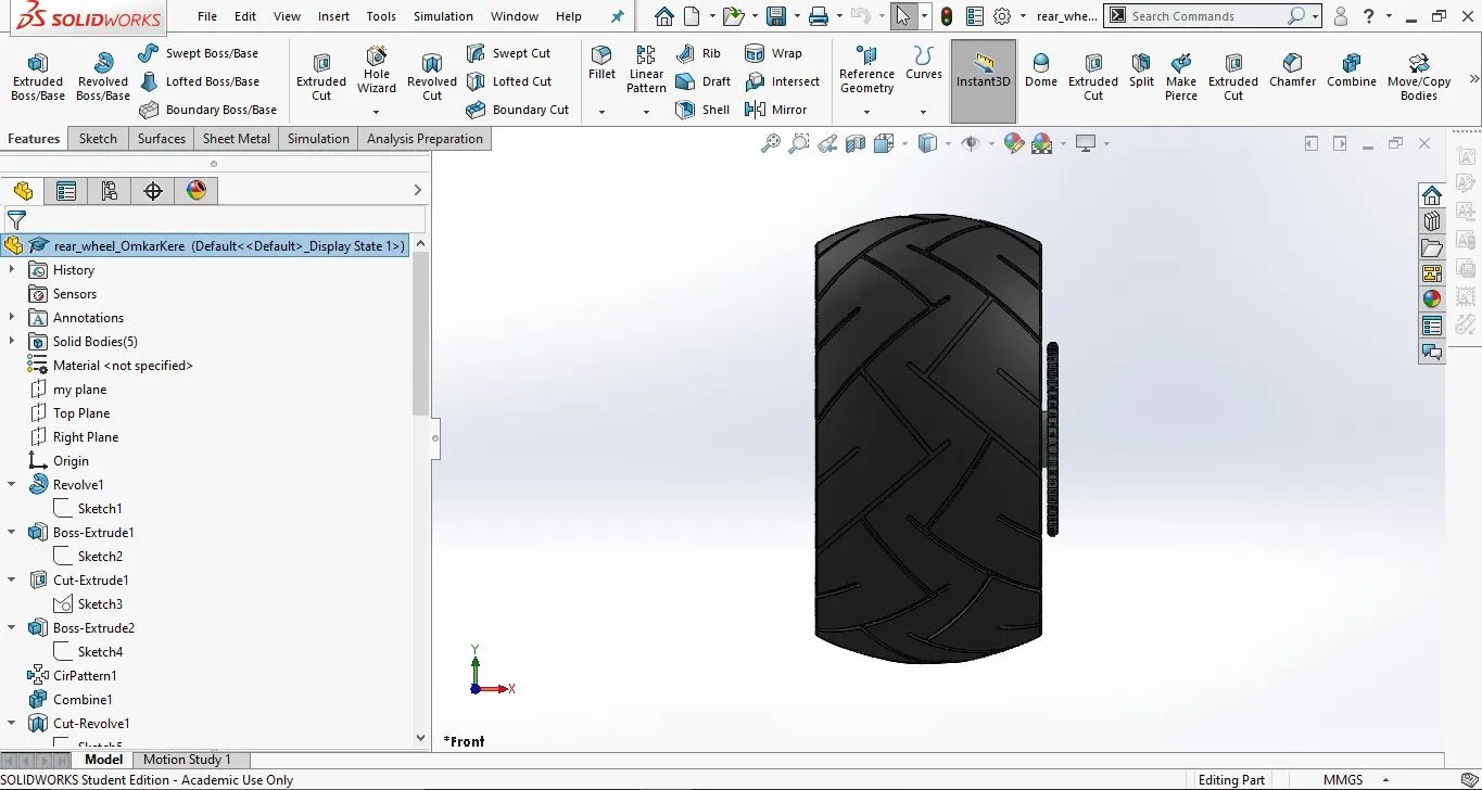
2. Side view:
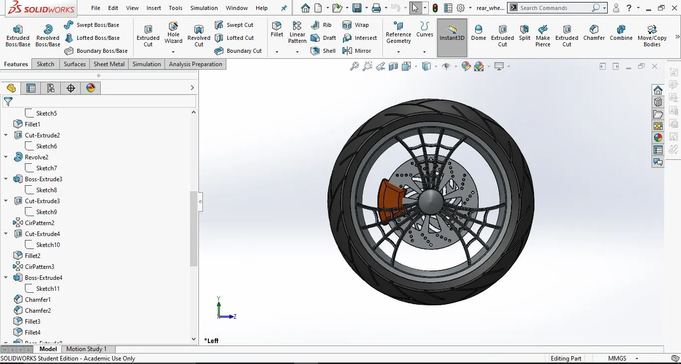
3. Isometric view:
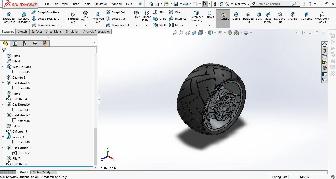
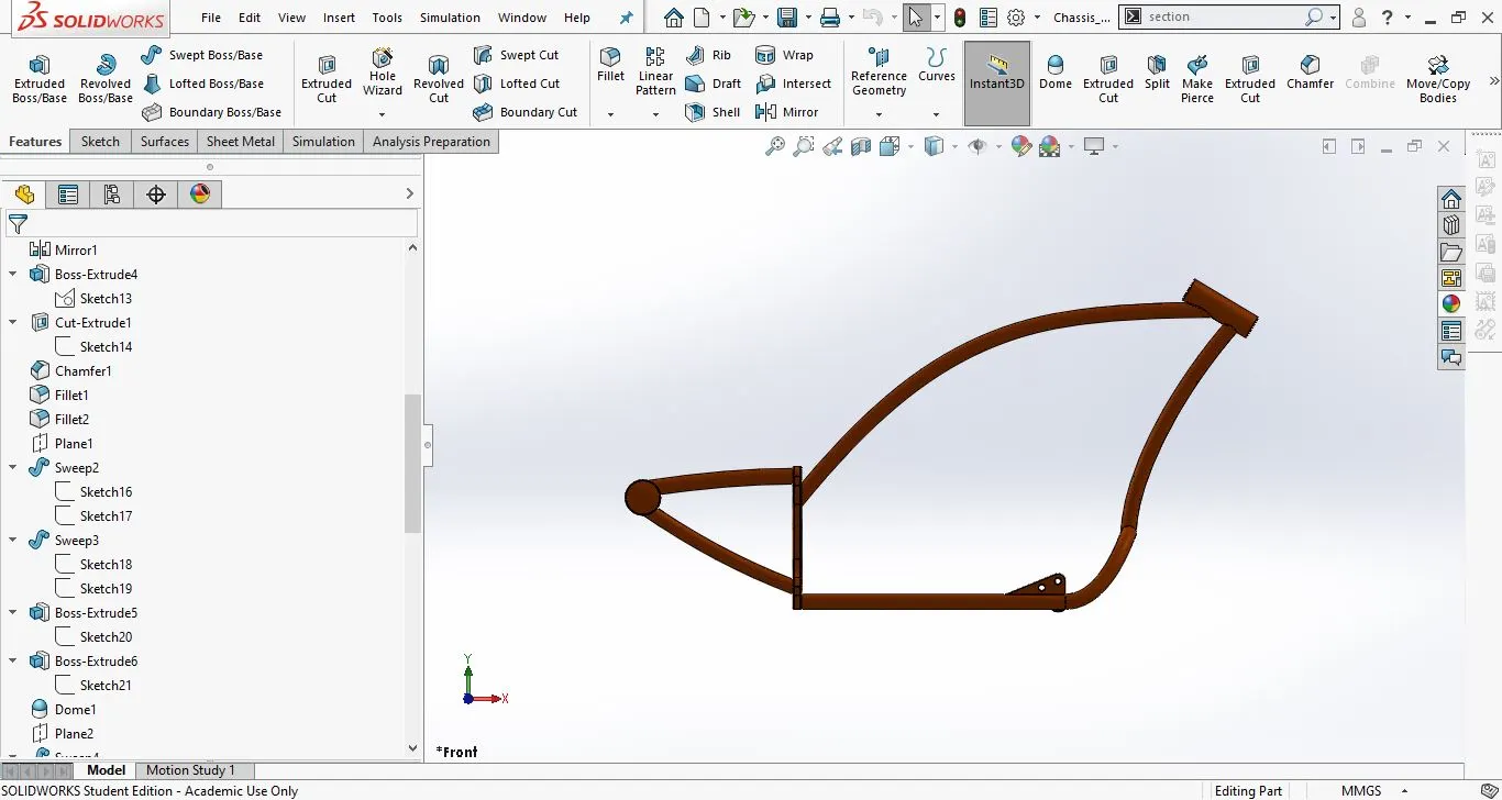
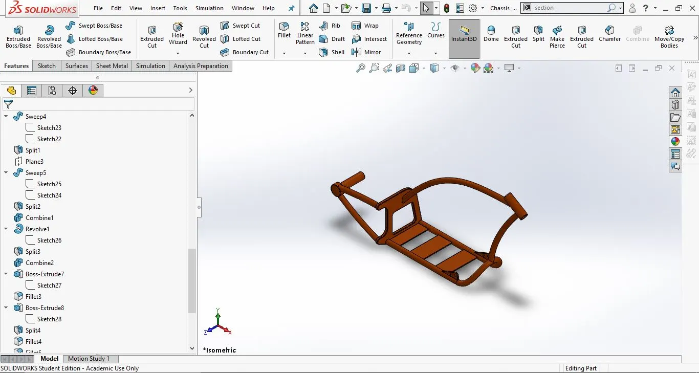
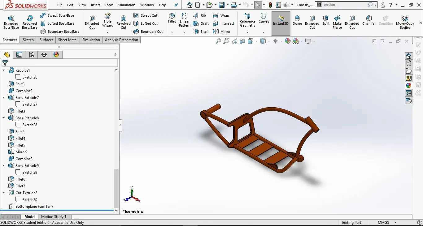
10. Chassis:
This is the main component of the chopper. All the parts are attached to the chassis. The chassis provides structural rigidity and support to the bike.
- Tools and features used;
- Sketch
- Sketch Picture
- Splines
- Projected curves
- Swept
- Trim
- Convert entities
- Combine
- Plane
- Make Pierce
- Part images with feature tress:
- . Front view;
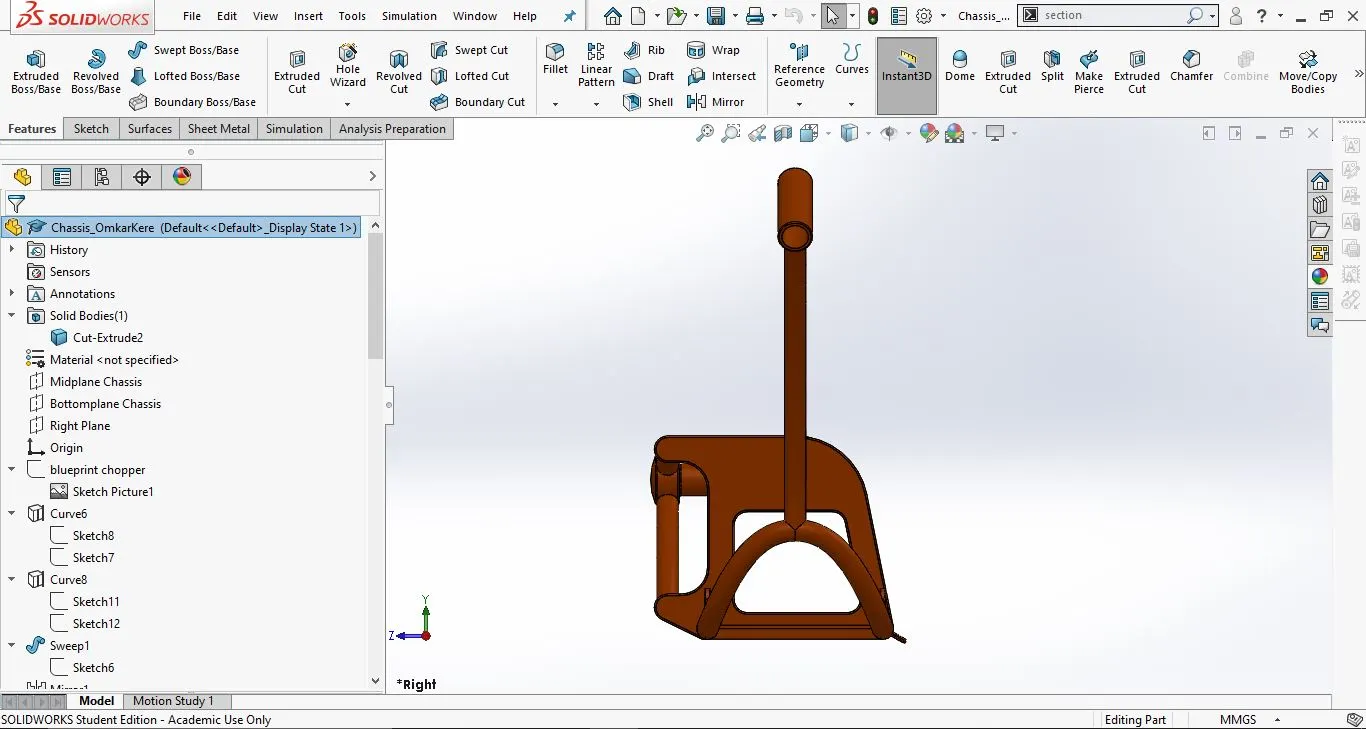
2. Side view:
3. Isometric view:
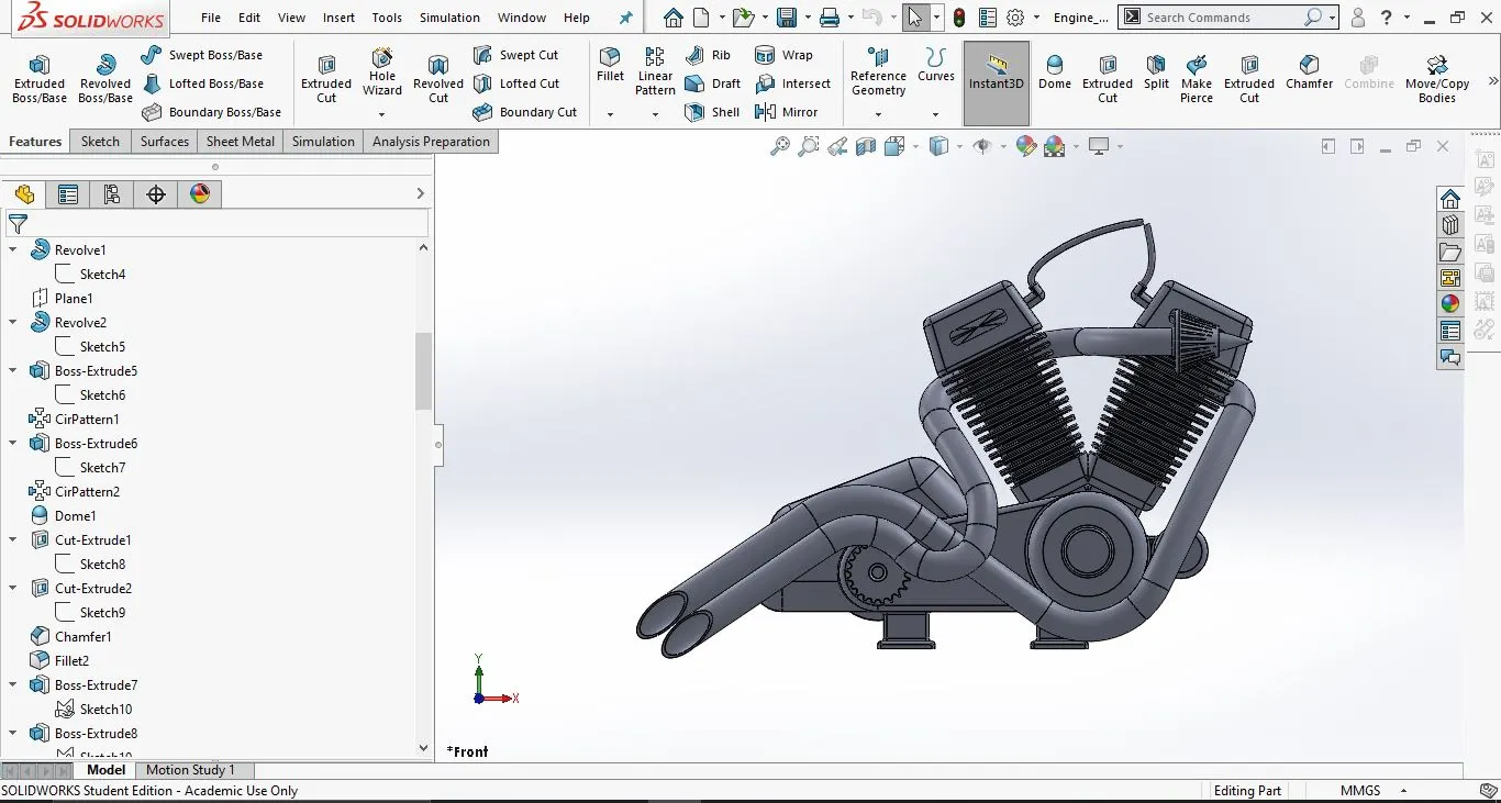
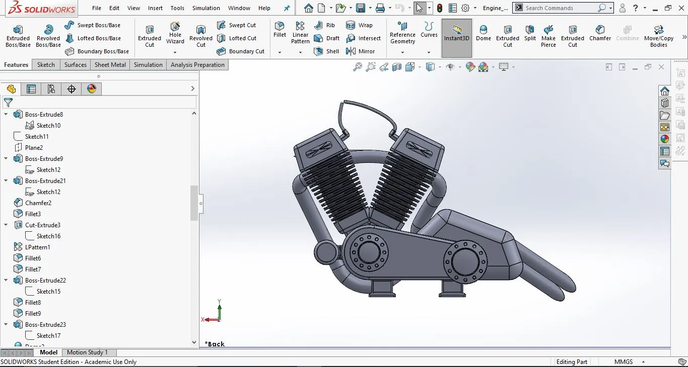
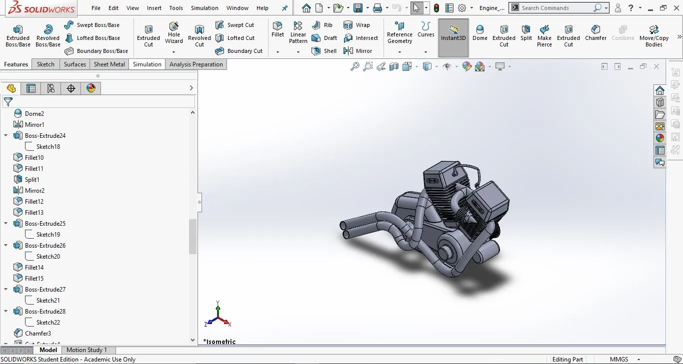
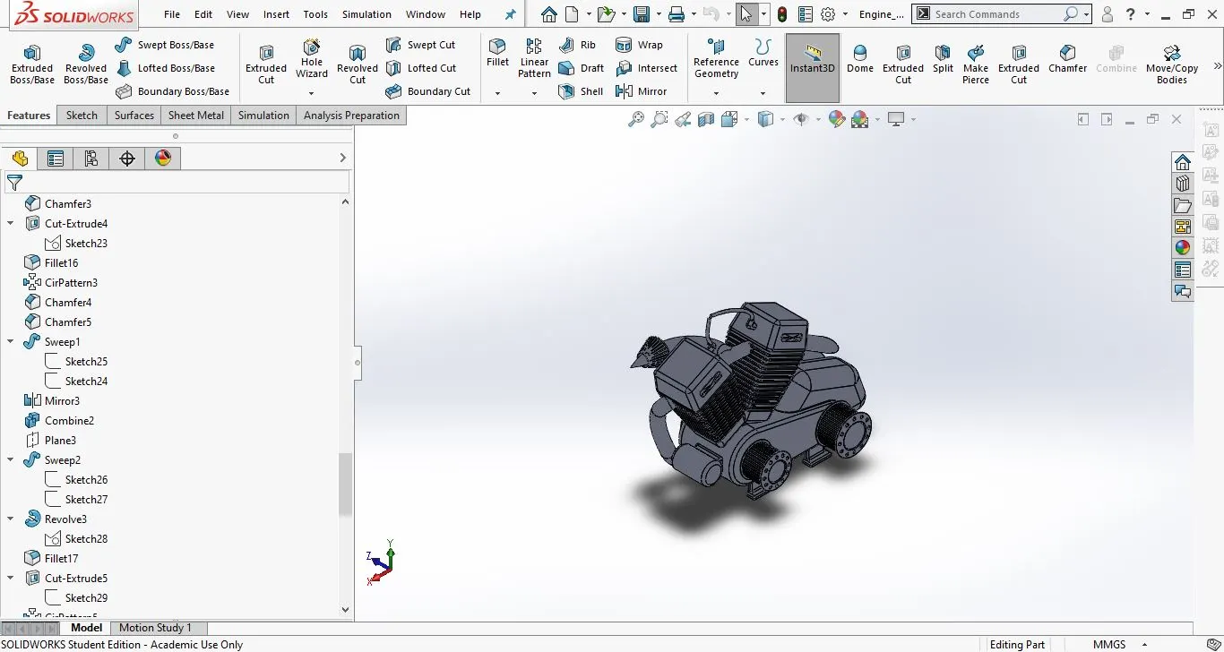
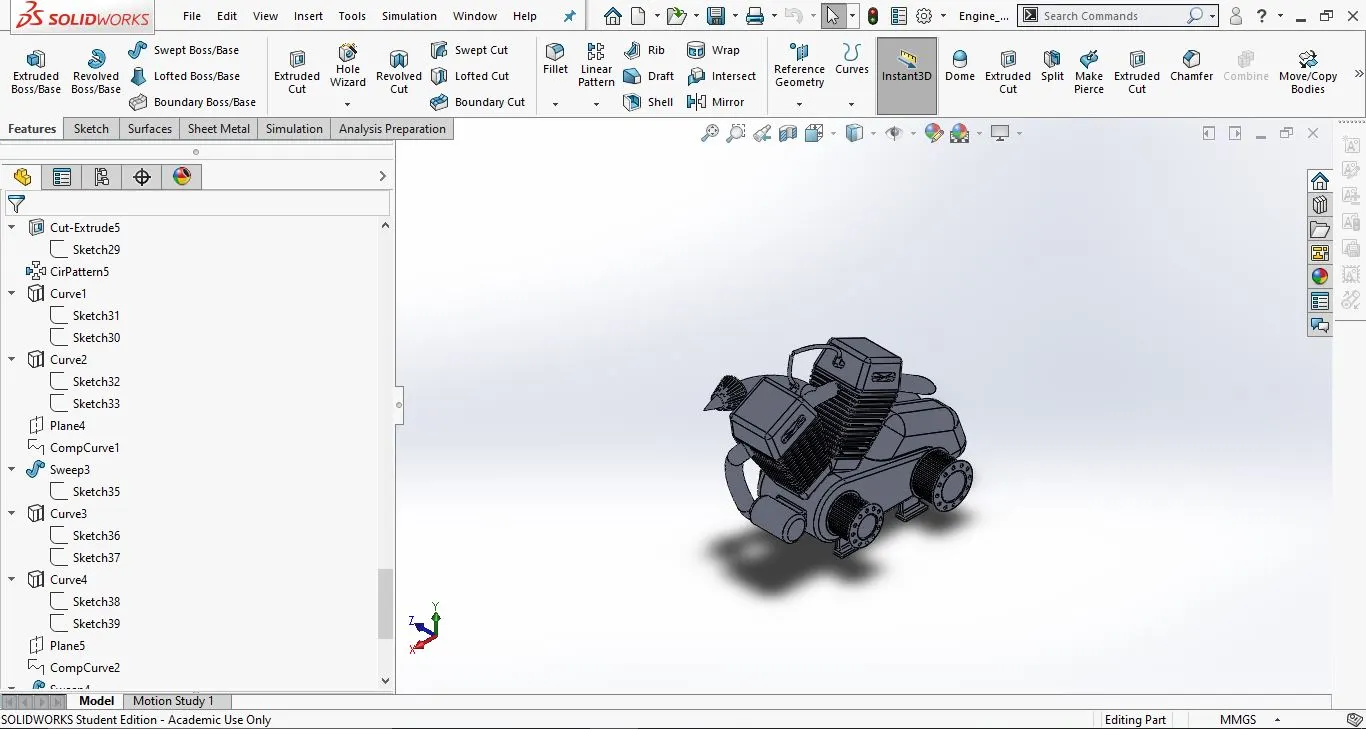
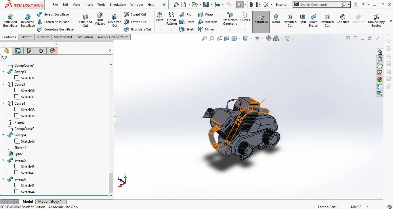
11. Engine
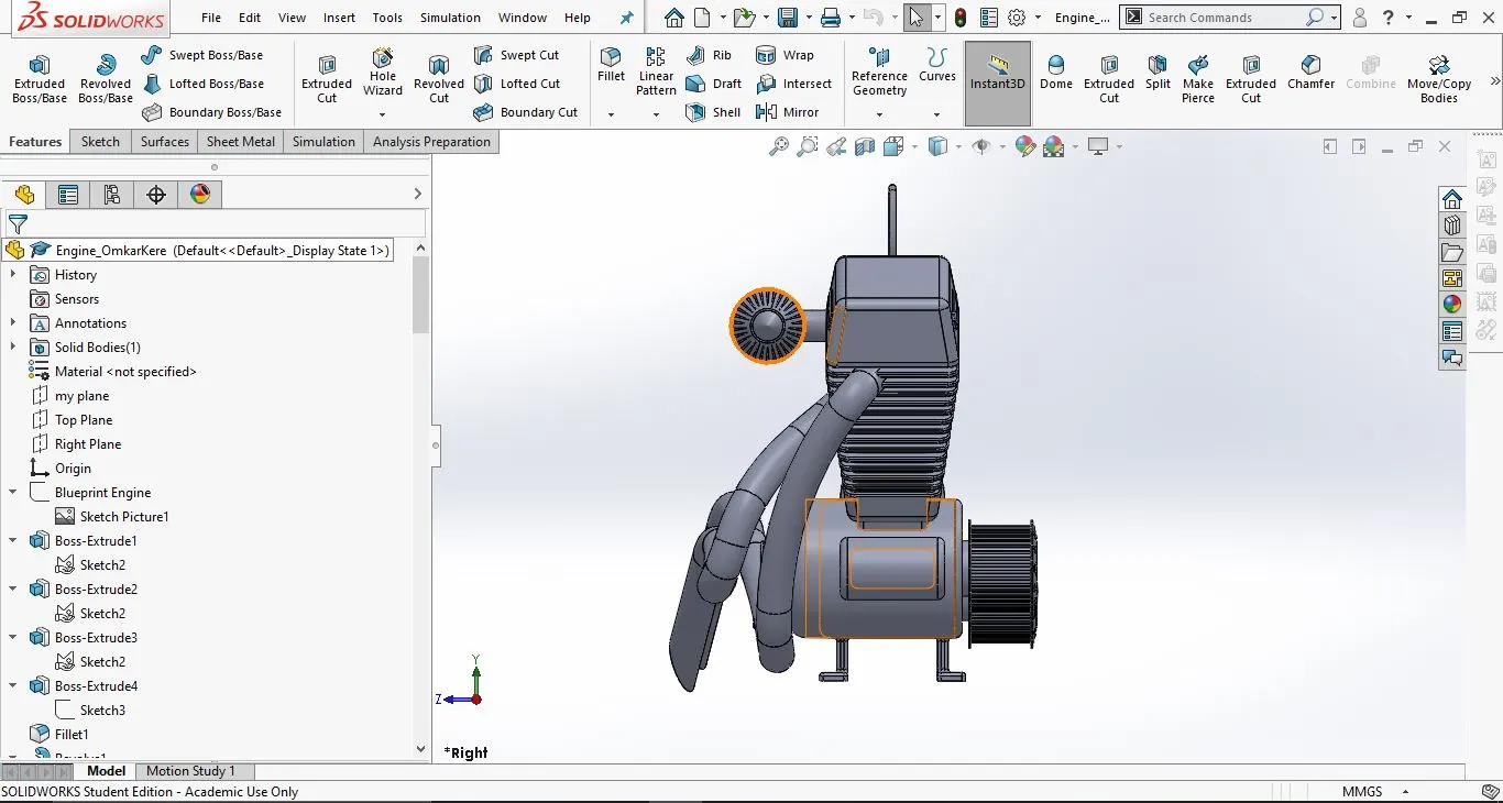
This the power house of the bike. The power is generated and transfered to the rear wheel via chain.
- Tools and features used:
- Sketch
- Line
- Extrude bose
- Dome
- Extrude Cut
- Circular Pattern
- Fillet
- Chamfer
- Loft
- mirror
- Combine
- Part images with feature tree:
- Front view:
2. Side view:
3. Isometric view:
12. Front fork:
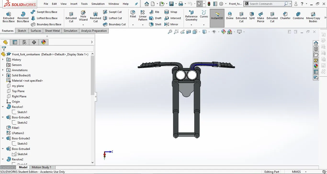
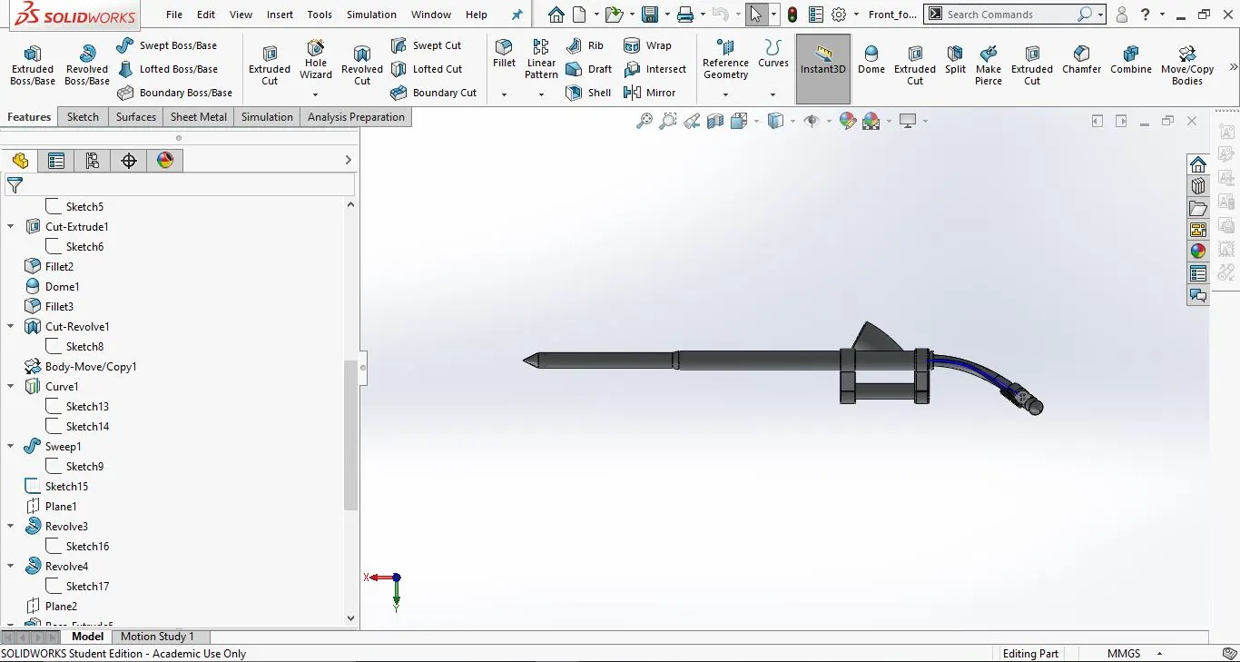
This is the part on which the front wheel is attached. It is connected to the chassis and is used for stearing the bike.
- Tools and features used:
- Sketch
- Line
- Revolve
- Move/Copy bodies
- Mirror
- Extrude Bose
- Extrude cut
- Dome
- Plane
- Swept
- Combine
- Projected curve
- Part images with feature tree:
- Front view:
2. Side view:
3. Isometric view:
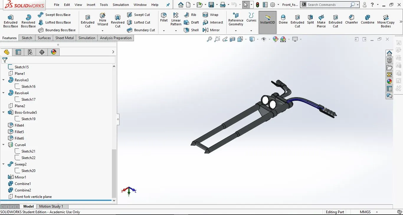
13. Fuel tank:
This is where the fuel for the chopper is stored.
- Tools and features used:
- Sketch
- Spline
- Projected curves
- Line
- Surface Extrude
- Surface sweep
- Surface trim
- Surface loft
- Mirror
- Boundry surface
- Surface Knit
- Fillet
- Shell
- Swept cut
- Plane
- Part images with feature tree:
- Front view:
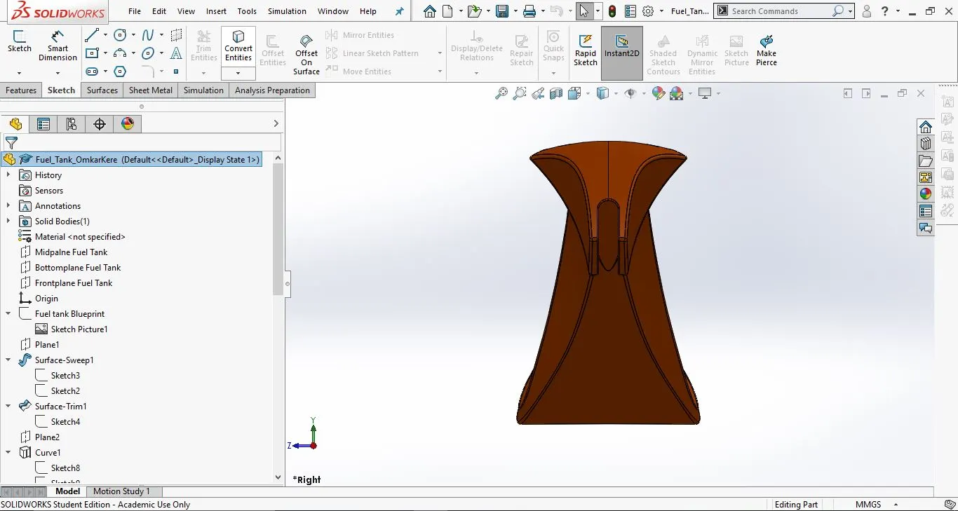
2. Side view:
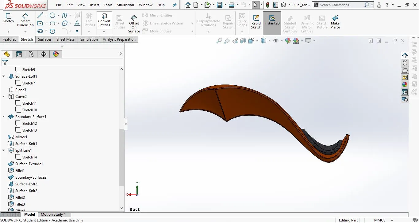
3. Isometric view:
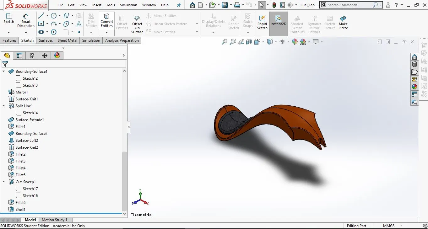
- Assembly of the chopper:
- The assembly of the chopper is done in the assembly window of the SolidWorks
- The chassis is inserted first and constrained with the assembly planes.
- Then the parts are inserted and mated with the chassis and not the assembly planes, this is done so that the entire assembly moves if the chassis is moved.
- Mates used:
- Concentric
- Coincident
- Paralell
- Angle mate
- Width
- Distance
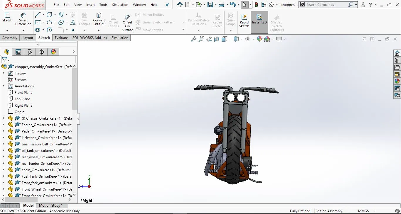
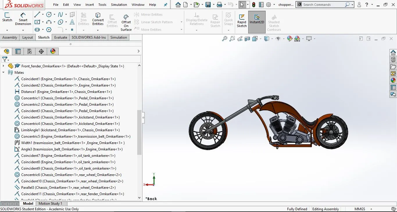
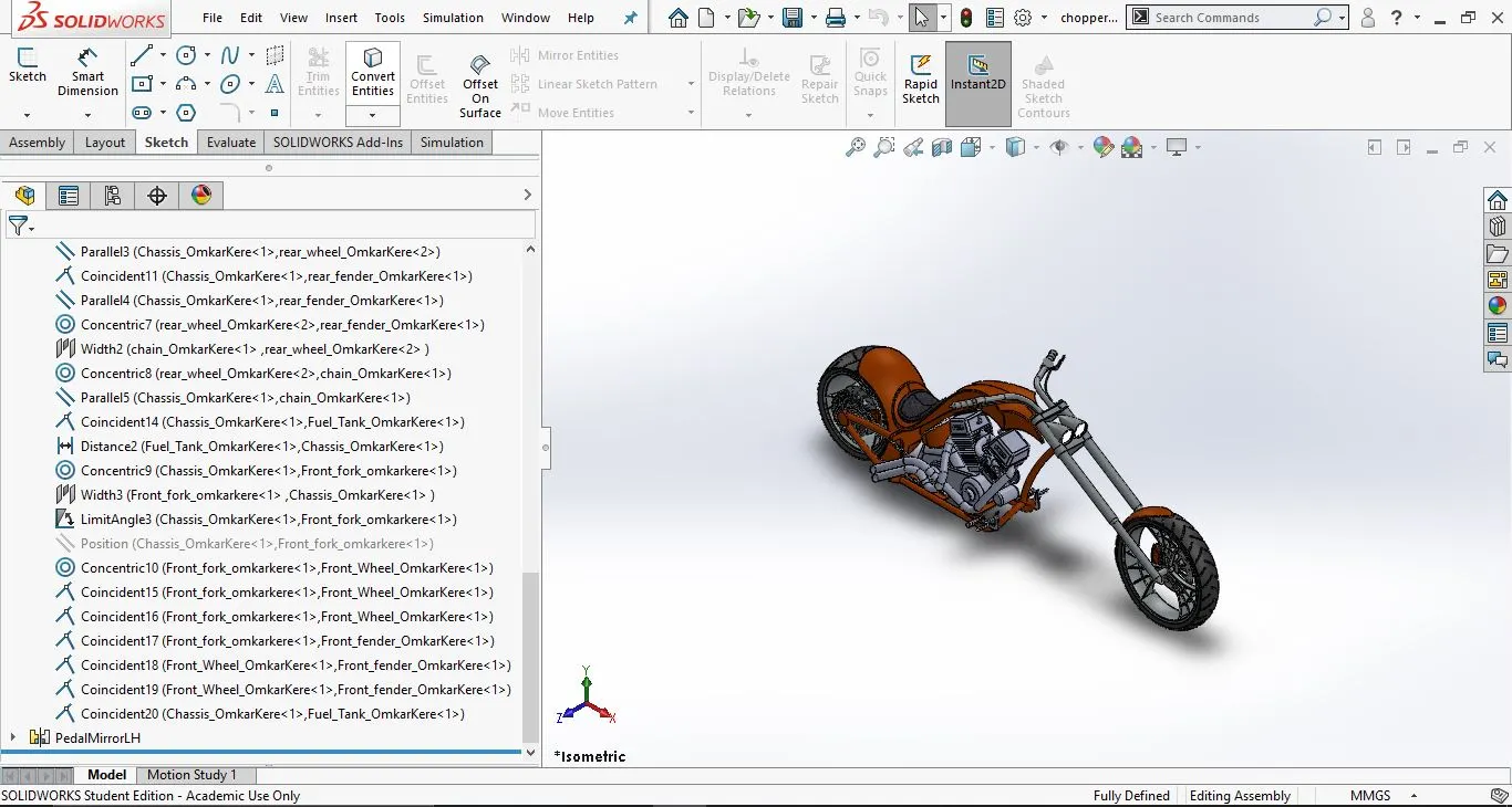
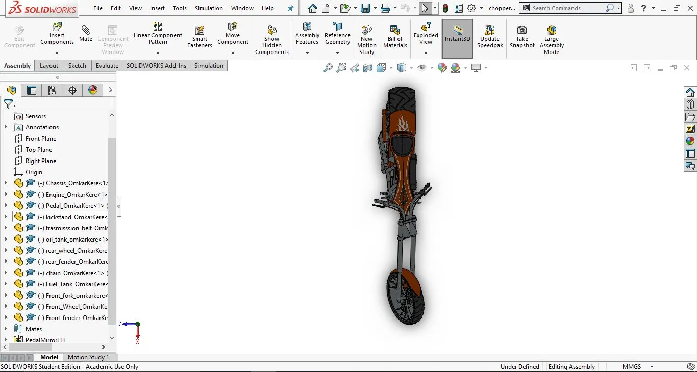
- Assembly images with mate tree:
- Front view:
2. Side view:
3. Isometric view:
4. Top View:
5. Side view:
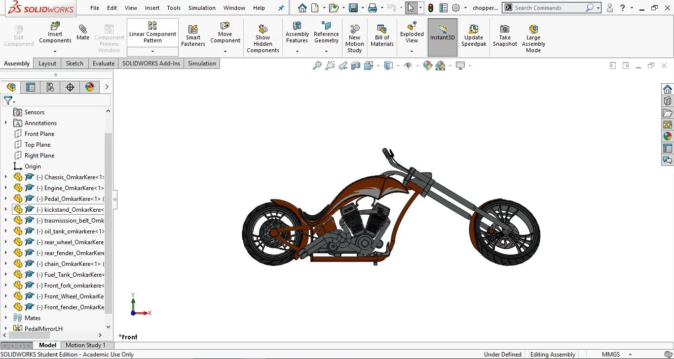
- Rendering of American Chopper using Photoview 360
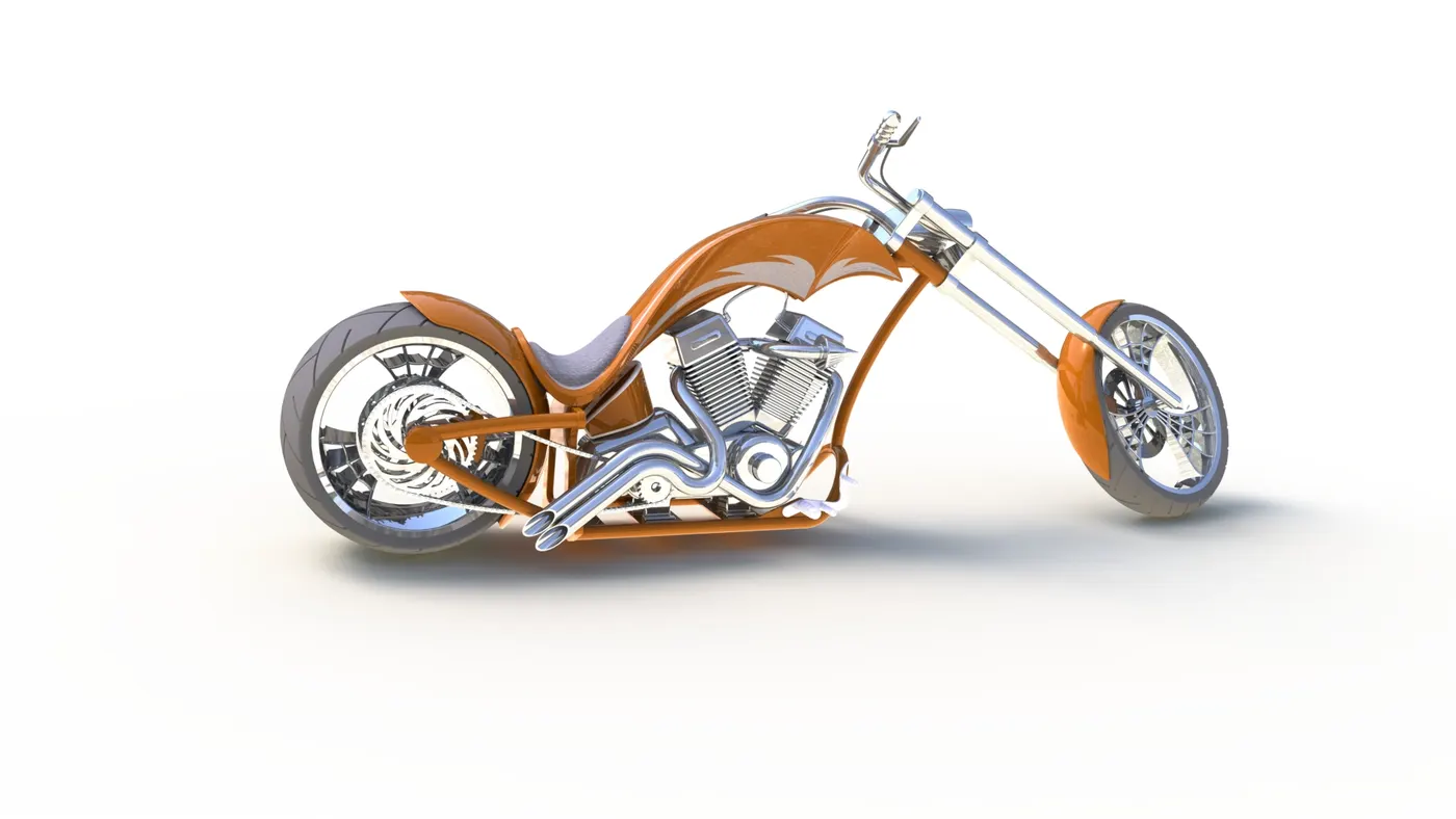
1. Decals are applied to the fuel tank and the rear fender using 'Edit Decal' option.
2. Make a tangent relation between Top plane of assembly and the front wheel, rear wheel and the kick stand. This makes the bike look tilted and more realistic.
3. Go to view and add camera with an appropriate position.
4. Finally Do a preview and perform a final render.
- Camera view:
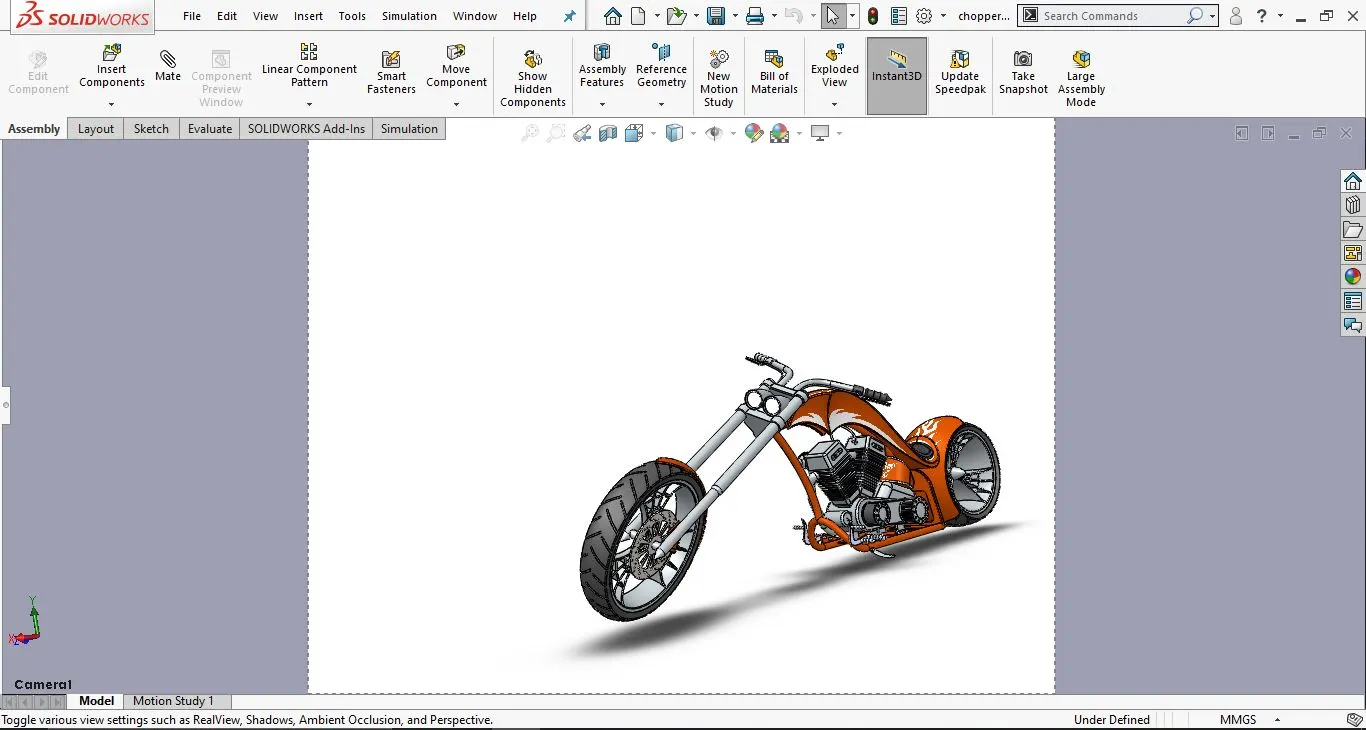
- Images rendered:
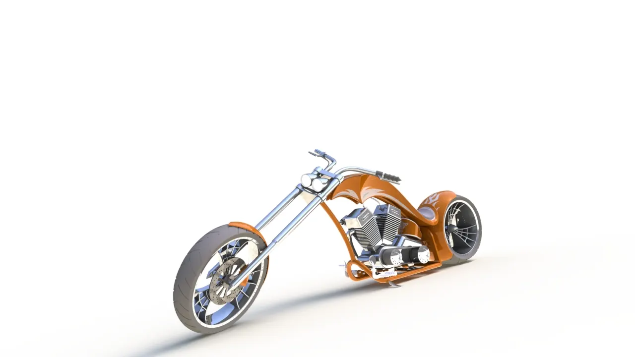
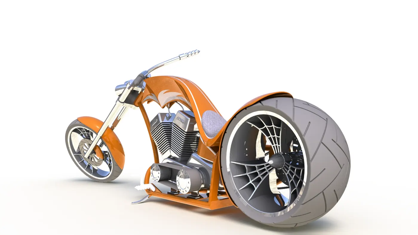
- Render images using SolidWorks Visualise
- The chopper model is imported into the SolidWorks visualise
- In enviornment option the appropriate enviormet is applied, in this case Route 66 enviornment.
- We can apply different paint if need
- The shadow and rotation is adjusted as well as the height of the enviorment until a satisfactory position of the bike is acquired.
- Click the output option choose the QUALITY render and give the number of passes and start render
- Images of the render: