Week 9:- 2D Detailing Challenge
1)Drawing Templates:
Drawing templates are files containing frames and title blocks that convey design information. They are used to generate 2D drawings from 3D parts. Neat and detailed drawing templates convey more information from the designer to the manufacturer, helping to avoid misunderstandings and ensuring the efficient production of parts, which ultimately saves time and money.
Key Information in Drawing Templates
- Company Name
- Project Name
- Sheet Size
- Sheet Number
- Angle of Projection
- Revision Number/Letter (if it's a revision drawing)
- Signatures or Names of:
- Drawn By
- Checked By
- Responsible Engineer
- Approved By
- Part Details
- Quantity
- Additional Notes (Surface Finish, Heat Treatment, Material Details, etc.)
- Scale, Date, Unit of Measurement
Standardization and Customization
Drawing templates are customized according to company standards. If provided by the customer at the beginning of the project, these templates are utilized. Otherwise, they are finalized at the start of the project to ensure consistency and compliance with project requirements.
2) The angle of projection refers to the angle at which an object is viewed or depicted in order to create a two-dimensional representation of it. In technical drawing and engineering, it specifically refers to the angle at which an object is observed in relation to the plane on which it is being drawn. This angle is crucial for accurately portraying the object's dimensions, proportions, and features in the resulting two-dimensional drawing. There are two common systems of angle projection used in a technical drawing: first-angle projection and third-angle projection. These systems define the arrangement of views in orthographic projection, influencing how the object is depicted on the drawing sheet.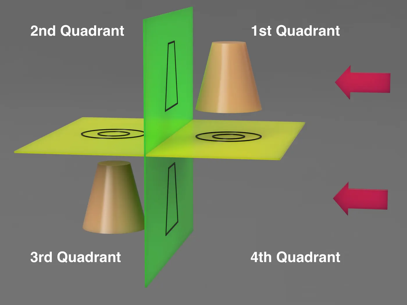
It refers to the angle at which an observer views an object to convert it from a three-dimensional (3D) object to a two-dimensional (2D) representation, such as drawing it onto a plane surface like paper. The two common angles of projection used in technical drawing are
1. First Angle of Projection: This corresponds to the first quadrant of the coordinate plane.
2. Third Angle of Projection: This corresponds to the third quadrant of the coordinate plane.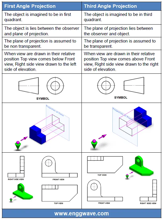
3) In technical drawing, the angle of projection refers to how an object is positioned relative to the projection planes in orthographic projection. There are two main systems: first-angle projection and third-angle projection.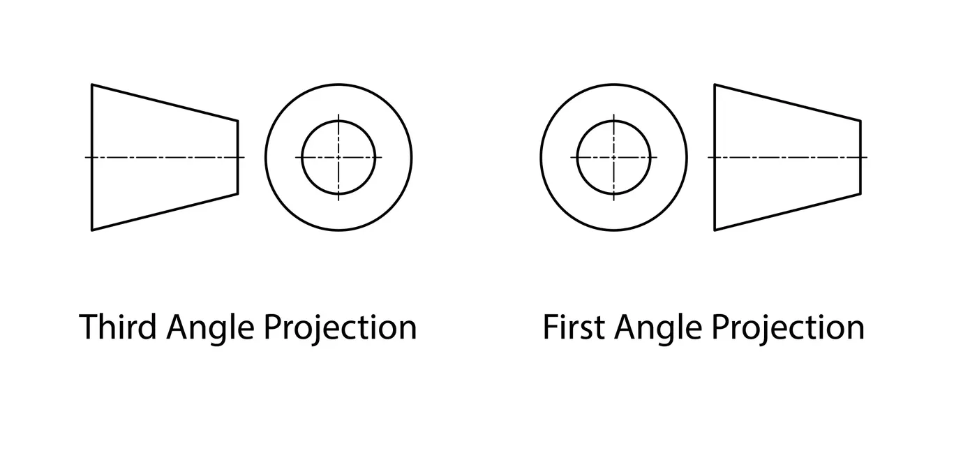
1. First Angle Projection:
- In this system, the object is placed in the first quadrant.
- The object is positioned in front of the vertical plane and above the horizontal plane.
- First angle projection is commonly used in India and European countries.
- The object is located between the observer and the projection planes.
- The projection plane is represented as solid in first angle projection.
2. Third Angle Projection:
- In the third angle projection system, the object is placed in the third quadrant.
- The object is positioned behind the vertical planes and below the horizontal plane.
- Third-angle projection is widely used in the United States.
- The projection planes are situated between the object and the observer.
- The projection plane is depicted as transparent in third-angle projection.
The second and fourth-angle projection systems have limitations that make them less practical for engineering drawings compared to the first and third-angle projection systems. Let's explore these limitations:
1. Confusion due to Overlapping Views:
- In the second angle projection system, the vertical plane lies between the object and the observer.
- For example, when considering a rectangular part placed in the second quadrant, the front view lies on the vertical plane, while the top view is on the horizontal plane.
- When the horizontal plane is rotated 90 degrees clockwise, the top and front views overlap, creating confusion in the drawing.
2. Ambiguity in Projection:
- Similarly, in the fourth angle projection system, when the object is placed in the fourth quadrant, both the top and front views overlap.
- This overlapping of projection views leads to ambiguity and difficulty in interpreting the drawing accurately.
Due to these limitations and the resulting confusion and ambiguity in the drawings, the second and fourth-angle projection systems are not commonly used in engineering drawings. Instead, the first and third-angle projection systems are preferred for their simplicity and clarity in representing three-dimensional objects in two dimensions. Understanding these limitations helps to appreciate the rationale behind the widespread use of first and third-angle projection systems in engineering drawings.
In orthographic projection, where drawing views are derived from three-dimensional objects onto two-dimensional planes, the second and fourth-angle projection systems present significant limitations, leading to their infrequent use in engineering drawings. Here's why:
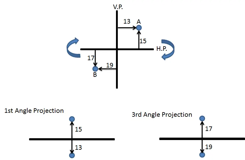
1. Second Angle Projection (Object X in Second Quadrant):
- In this system, the vertical plane (VP) lies between the object (Object X) and the observer.
- Consequently, the front view of Object X is depicted on the vertical plane, while the top view is illustrated on the horizontal plane.
- When the horizontal plane is rotated 90 degrees clockwise, as per the rule of projection, the top and front views overlap.
- This overlapping creates confusion in the drawing, as it's challenging to distinguish between the top and front views, leading to potential misinterpretations and errors.
2. Fourth Angle Projection (Object in Fourth Quadrant):
- Similarly, in the fourth angle projection system, when the object is situated in the fourth quadrant, both the top and front views overlap.
- Again, the overlapping of projection views results in confusion and ambiguity in the drawing.
- With both top and front views merging, it becomes difficult to discern the object's features accurately, leading to potential inaccuracies in the representation.
Due to the inherent challenges of overlapping projection views and the resulting confusion in interpreting the drawings, the second and fourth-angle projection systems are not commonly utilized in engineering drawings. Instead, the first and third-angle projection systems are preferred for their clarity and simplicity in representing objects in two dimensions. Understanding these limitations underscores the rationale behind the prevalent use of the first and third-angle projection systems in engineering practices.
4) GD&T, or Geometric Dimensioning and Tolerancing, is a symbolic language used on engineering drawings and computer-generated solid models to define and communicate engineering tolerances. Here are some benefits of using GD&T: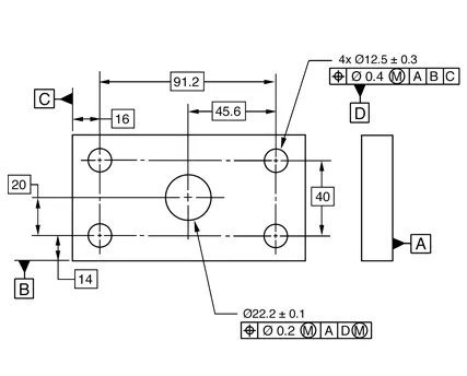
1. Cost Savings: GD&T enhances design accuracy by specifying appropriate tolerances, which can optimize production processes. Additionally, it may provide extra or bonus tolerances in some cases, further increasing cost-effectiveness.
2. Ensuring Dimensional and Tolerance Requirements: By explicitly stating all design requirements, GD&T ensures accurate fulfillment of dimensional and tolerance specifications. This helps avoid errors and ensures that parts and assemblies meet quality standards.
3. Supporting Digital Design Methods: GD&T data can be easily integrated into digital design programs, including 2D and 3D computer-aided design (CAD) software. This facilitates the use of advanced digital design and manufacturing techniques.
4. Uniformity and Consistency: GD&T provides a single, consistent language for specifying geometric tolerances. This reduces guesswork and interpretation, leading to consistent geometries across the design and manufacturing process.
5. Accurate Communication: In today's complex engineering environment, accurate communication is crucial. GD&T enables designers, manufacturers, and inspectors to communicate design requirements clearly and effectively, reducing errors and saving time in the manufacturing process.
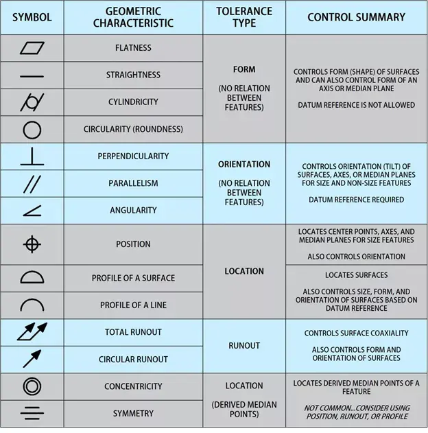
5)
1. Feature Control Frame: This is a rectangular box that contains all the GD&T information for a specific feature on the drawing. It typically includes symbols for geometric tolerances, datum references, and other relevant information.
2. Datum Feature Symbol: A datum feature symbol identifies a part feature that is used as a reference for establishing geometric tolerances. It is represented by a letter (e.g., A, B, C) enclosed in a circle. Multiple datum feature symbols may be used on a drawing to establish multiple reference planes.
3. Feature Control Symbol: This symbol indicates the type of geometric tolerance applied to a feature. Common feature control symbols include:
- Straightness: Represents the straightness tolerance of a feature.
- Flatness: Indicates the flatness tolerance of a surface.
- Circularity: Specifies the circularity tolerance of a circular feature.
- Cylindricity: Indicates the cylindricity tolerance of a cylindrical feature.
- Profile: Defines the profile tolerance of a feature's surface.
4. Position: The position symbol indicates the allowable deviation of a feature's location from its specified position. It is represented by a circle with a perpendicular line extending from it, accompanied by a tolerance value.
5. Concentricity: This symbol represents the tolerance for the coaxial alignment of two features, such as a hole and a shaft. It is depicted by two concentric circles with a centerline passing through their centers.
6. Symmetry: The symmetry symbol indicates that a feature's axis or center plane must be symmetrical relative to a datum reference. It is represented by a line with arrows pointing in opposite directions.
7. Circular Runout: Circular runout specifies the allowable variation in the circularity of a feature as it rotates about its axis. It is depicted by a circular symbol with a circular arrow around it, along with a tolerance value.
8. Total Runout: Total runout specifies the overall variation of a feature's surface or axis when it is rotated about any axis. It is represented by a circular symbol with two concentric circles around it, along with a tolerance value.