Week 9.1: Turbo Charger Simulation Project
Aim - Turbo Charger Simulation in Converge 3.0
Introduction - A Proportional valve is used as a safety device in systems where the machines interact with high pressures. The protection is done by preventing pressure exceeding the desired limit in a process system by releasing a volume of fluid from the process when a predetermined maximum pressure is reached thereby reducing excess pressure.
Turbo Charger -
A turbocharger, colloquially known as a turbo, is a turbine-driven forced induction device that increases an IC engine's efficiency and power output by forcing extra compressed air into the combustion chamber This improvement over a naturally asperated's power output is due to the fact that the compressor can force more air and proportionately more fuel-into the combustion chamber than atmospheric pressure (and for that matter, ram air effects) alone.
Turbochargers were originally known as turbosuperchargers when all forced induction devices were classified as superchargers. Today, the term "supercharger is typically applied only to mechanically driven forced induction devices. The key difference between a turbocharger and a conventional supercharger is that a supercharger is mechanically driven by the engine, often through a belt connected to the crankshaft whereas a turbocharger is powered by a turbine driven by the engine's exhaust gas .compared with a mechanically driven supercharger. turbochargers tend to be more efficient but less responsive. Twincharger refers to an engine with both a supercharger and a turbocharger.
Geometry -
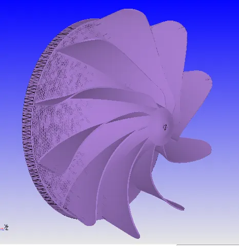
- Geometry creation-
- Drag-drop
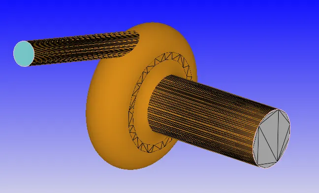
- Boundary Flagging
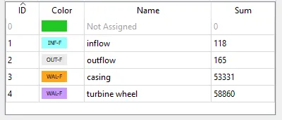
- Boundaries were defined using the Boundary function
- 4 different boundaries were defined as follows -
Case Setup
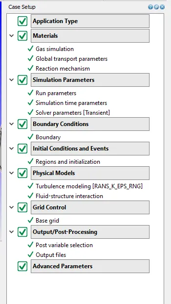
- Application type > Time-based
- Materials> Select Predefined mixture "Air"
- O2 and N2 Gas species added
- Simulation parameters
- Run Parameters - Transient -
- Simulation time parameters - 0.006s
- Solver parameters - Density-based NS solver
- Run Parameters - Transient -
- Boundary conditions-parameters assigned as follows
- Inlet -
- Inflow Type -
- Inlet - 250000.0 Pa, 800KAir Species
- Outlet -
- Outflow Type - 100000.0Pa. 300K. Air Species
- Casing - Wall - Law of wall - 450.0K Temp
- Turbine wheel - FSI - 300 k
- Inlet -
- Initial Conditions and Events
- Region and initialization Add Volumetric Region with Air species. Initial pressure-Inlet pressure - 101325.0Pa. 500K.
- Physical Models -
- Turbulence Model - RNG-k-e
- Transient cases only - FSI -
- Turbine wheel added as FSI object
- Mass flag - 0.15kg
- 1DOF rotation in z-direction - wheel axis
- Grid Control
- Base Grid - 0.002x0.002x0.002 m
- Output/Post-processing
- Time interval 3D O/p files - 6e-05s
- Advanced Parameters
Observations - After running the calculation on Cygwin following are the results observed in Paraview and Converge Line plotting tool. We observe that as the lift increase the velocity and mass flow rate increases & the pressure on the spindle decreases. Also, the total pressure in the system/valve increases as the lift increases. The AMR results are more close the actual/practical value since the mesh is refined as compared to without AMR.
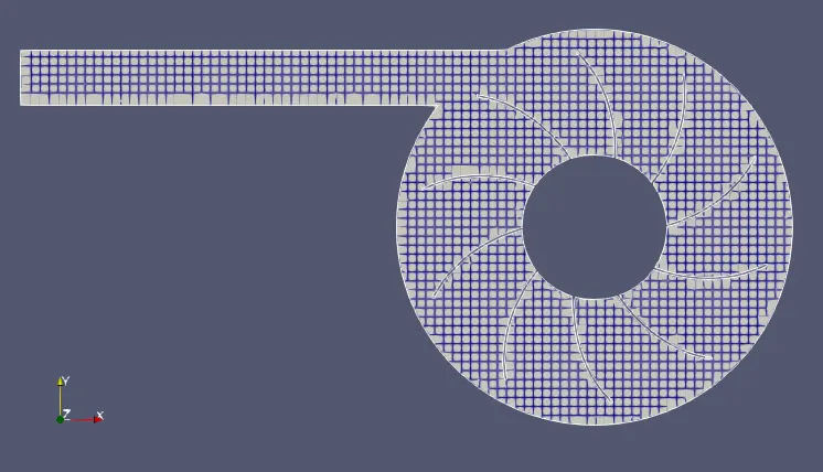
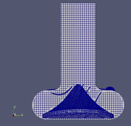
- Mesh
-
- Total Cells count
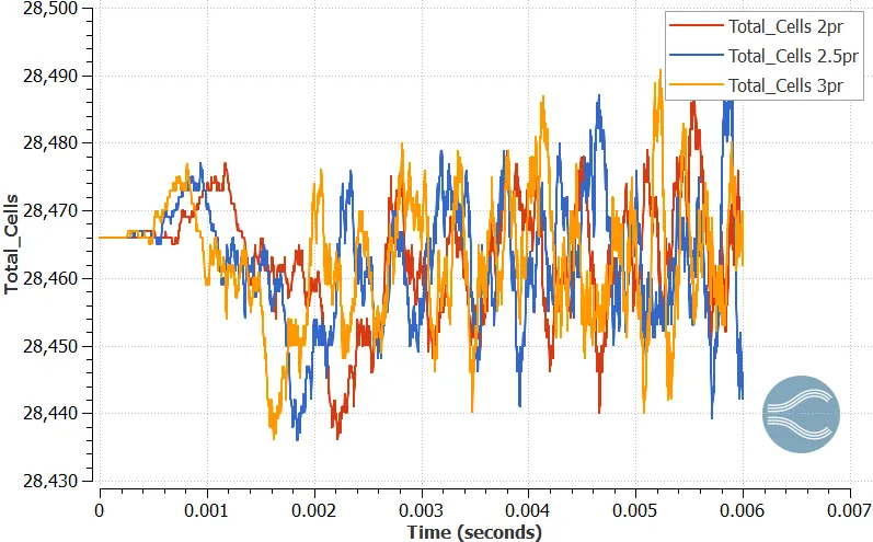
- The cell count and mesh varies overtime for all 3 pressure ratios
- Mass flow rate
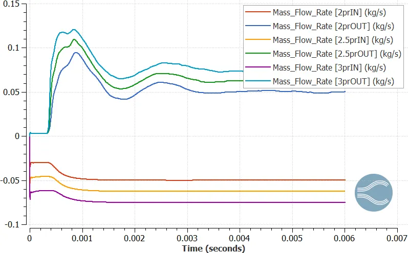
- Mass flow rate converges at the end of the simulation time. Also, the Mass flow in = Mass flow out for the respective pressure ratios
- Torque
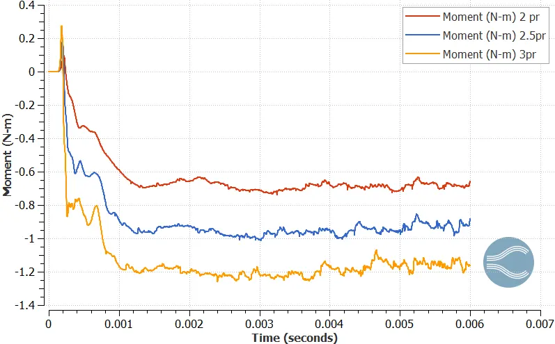
- As the pressure ratio increases, the torque also increases.
- Rotational velocity
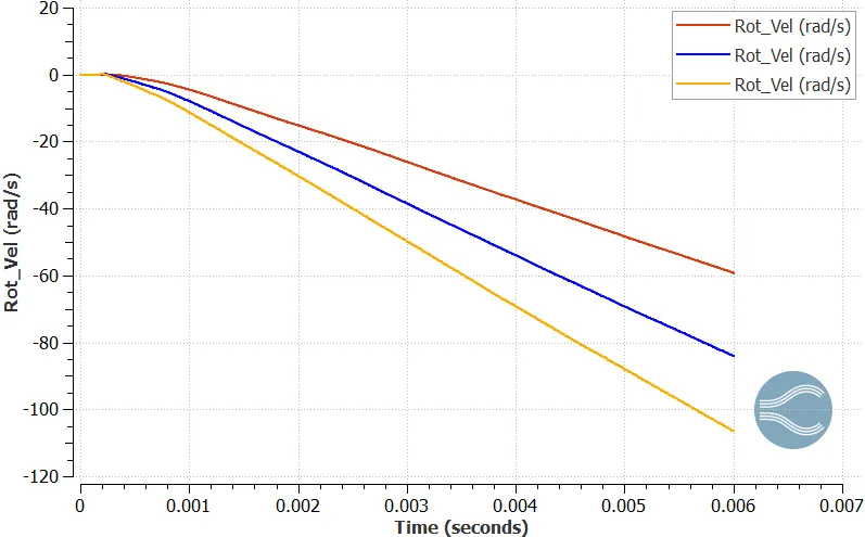
- The rotation velocity increase as the Pressure ratio increases. Also the turbine has not reached its max rpm since the plot is not converged, so to find max rpm we would have to run the sim for more time(s)
- Speed of the turbine -
-
Pressure Ratio Speed rad/s Speed rpm 2 58 585 2.5 83 838 3 106 1070
- Pressure on the turbine is asymmetrical and also the turbine wheel starts to move after a while when the torque starts to act on the impeller.
- Animation link - https://youtu.be/HSw1tBPEYq8 , https://youtu.be/2oW3QqjvOf0
-
Conclusion -
- All required RPM's of turbocharger at 3 pressure ratios were calculated at the end of the simulation time.