Week 4.2: Project : Transient simulation of flow over a throttle body
Aim - Transient simulation of flow over a throttle body in Converge 3.0
Introduction - Observing the flow over a throttle body at a stationary position.
Theory -
Geometry -
- Geometry creation-
- Geometry was Imported. Drag-Drop
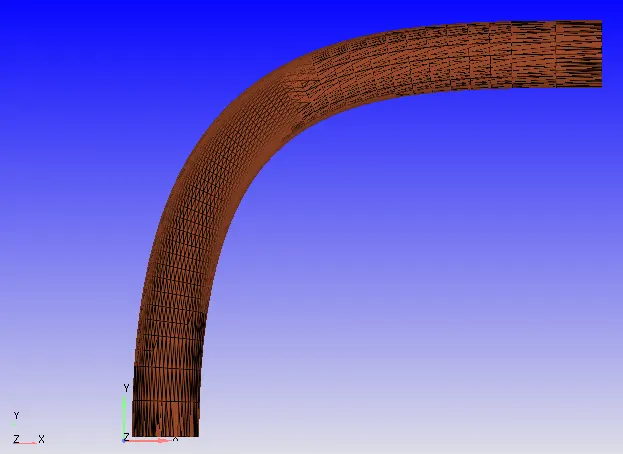
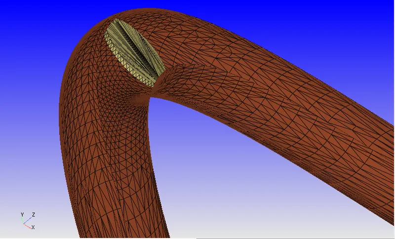
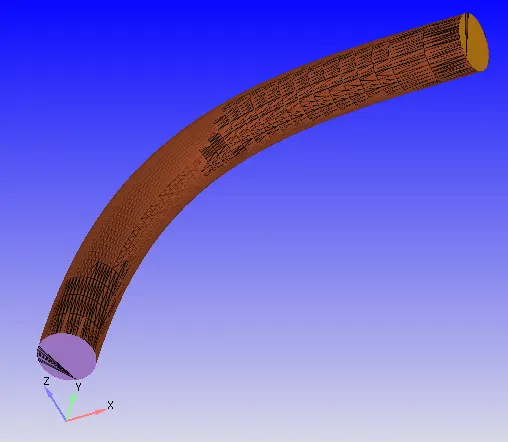
- Boundary Flagging
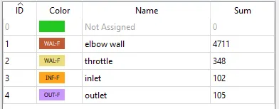
- Boundaries were defined using the Boundary function
- 4 different boundaries were defined as follows -
Case Setup
- Application type > Time-based
- Materials> Select Predefined mixture "Air"
- O2 and N2 Gas species added
- Simulation parameters
- Run Parameters - Transient
- Simulation time parameters-End time 0.01s - Time taken for the flow to take place through the approx 0.2m elbow at 80m/s will be around 0.002s. Considering convergence in floe after some time 0.01s sim time.
- Solver parameters - Density-based NS solver
- Boundary conditions-parameters assigned as follows
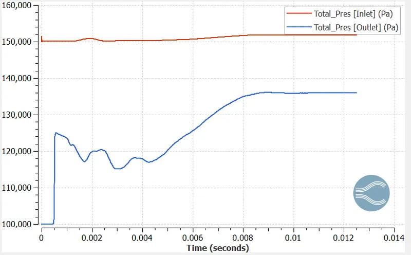
- Inlet - Inflow Type-150000Pa. 300K, Air Species
- Outlet - Outflow Type-100000Pa. 300K. Air Species
- Elbow wall - Wall - Law of wall - Rotating motion / Moving movement > Rotation rate file - 0 - 25Deg in 0 to 0.002s / 25Deg till 0.004s / 25 - 0Deg in 0.004 to 0.008s
- Throttle - Wall - Law of wall - Fixed movement
- Initial Conditions and Events
- Region and initialization Add Volumetric Region with Air species. Initial pressure-Inlet pressure - 101325.0Pa. 300K.
- Physical Models - Turbulence Model - RNG-k-e
- Grid Control
- Base Grid - 0.002x0.002x0.002 m
- Fixed Embedding
- Boundary-Top and Bottom- Permanent-Scale-3. Embed Layers 2
- Output/Post-processing
- Time interval 3D O/p files - 0.00125s
- Advanced Parameters
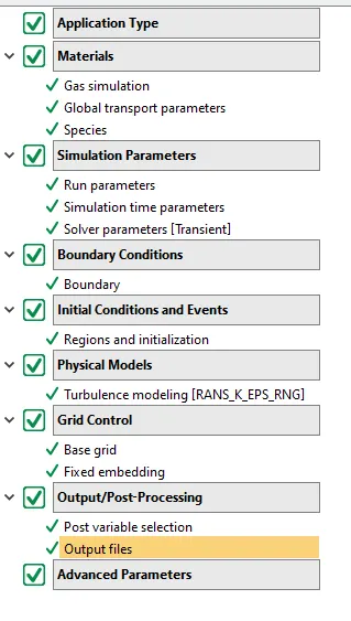
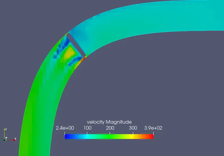
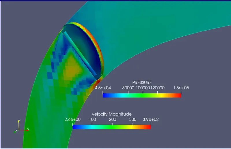
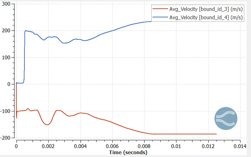
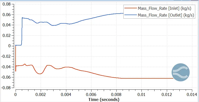
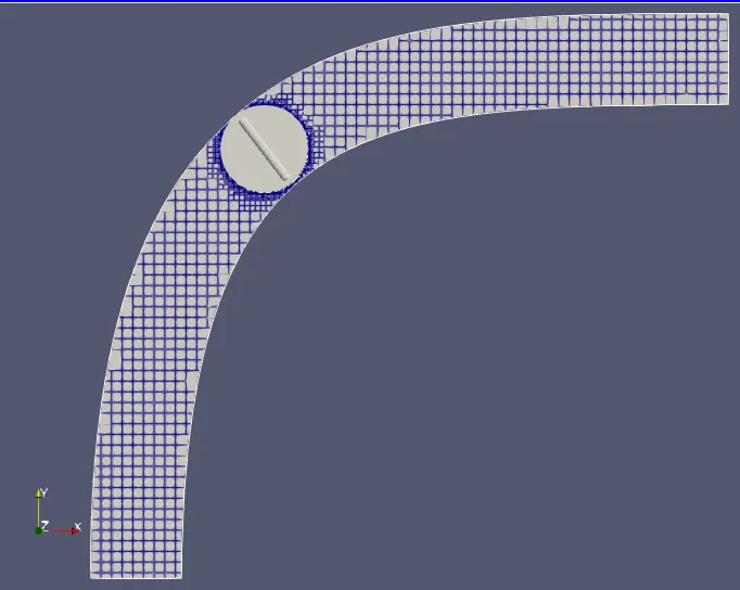
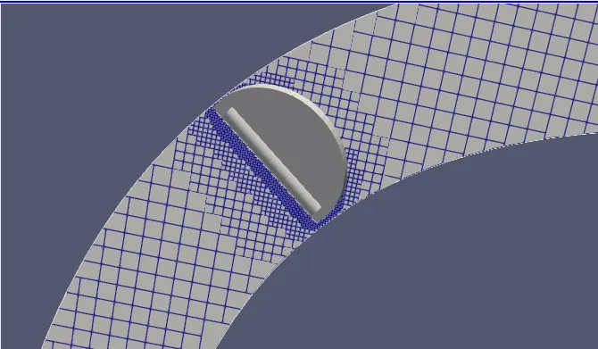
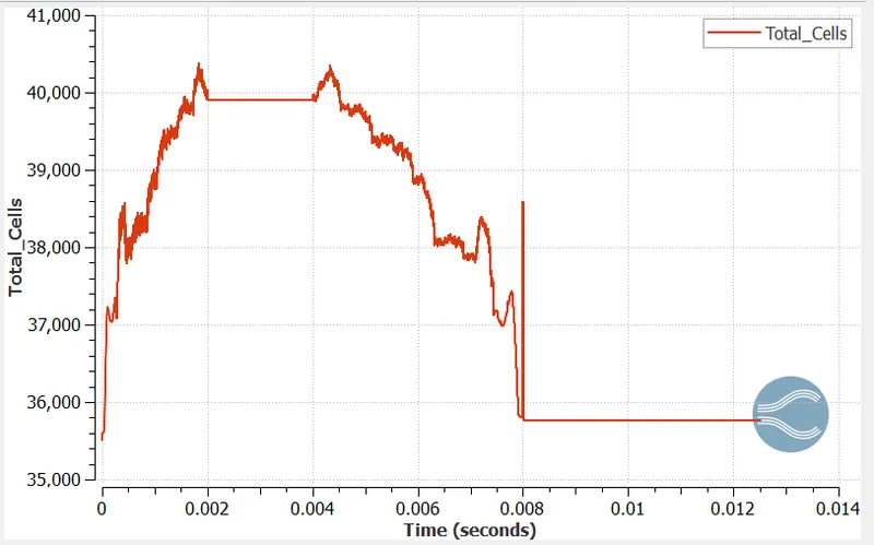
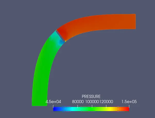
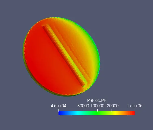
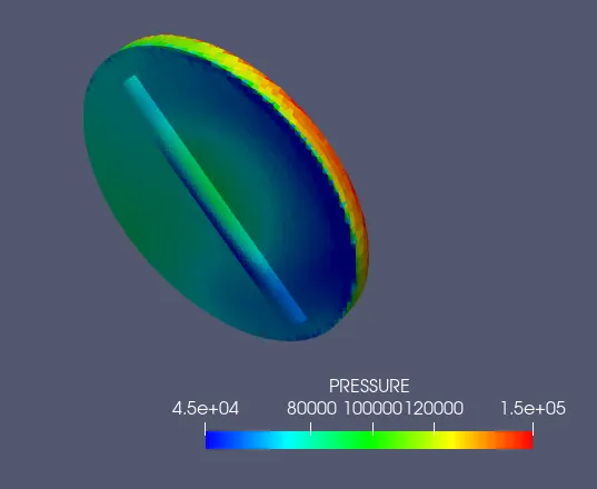
Observations - After running the calculation on Cygwin following are the results observed in Paraview and Converge Line plotting tool. The calculations were done with moving Throttle positions as mentioned above. At the start, we observed the pressure difference between Inlet and Outlet leading to a unidirectional flow through the channel. Flow over the throttle clearly visible in the below cases when the throttle is stationary. As the throttle starts closing, the pressure on the inlet side increases as compared to the region behind the throttle. The flow stabilizes and the inverse is seen once the throttle starts going back to the original position. The change in mesh/No of cells near the throttle while it is moving is also shown below. The effect on mass flow rate, pressure and velocity can be seen below mentioned plots.
- Mesh -
- Mesh and Cell count -
- Mesh after the throttle has partially closed
- Pressure across the Elbow and Throttle at 25 Deg rotation
- The front side of the throttle
- The backside of the throttle
- Velocity across the Elbow at 25 deg rotation
- Mass Flow rate across the Elbow
- Animation link - https://youtu.be/Ctr5Aeh1Cu0
-
Conclusion -
The flow over the throttle is observed and pressure on the throttle body close to the inlet is high.
In the velocity and pressure plots, we observed that Pressure and velocity are inversely proportional to each other
Flow can be observed from the High-pressure inlet to the Low-pressure outlet.
The mass flow rate plot varies as pe the opening that mass flow through the inlet equals mass flow through the outlet. No accumulation mass inside the channel.