Week 8 Worm Gear Challenge
Transient Structural Analysis of Worm Gear Assembly
OBJECTIVE
To perform a transient structural analysis of a Worm gear assembly and determine the results for Equivalent stress, Equivalent elastic strain and the total deformation in the model.
CASE SETUP
- Material Selection
In Materials, Structural Steel is by default applied to all bodies/components i.e. worm wheel & worm.
- Geometry
An assembly of meshed worm wheel & worm is directly imported in the workbench from available sources. In order to keep the mesh elements within academic limits, worm wheel is cut symmetrically into half parts and only one half part is simulated in the following simulation.
- Meshing
Program controlled mesh with mesh element size of 3mm is used in the following simulation.
- Setup
- Joints
Revolute joint is assigned to both the worm wheel and the worm about the axis of their rotation w.r.t ground.
- Setup
- Joints
Revolute joint is assigned to both the worm wheel and the worm about the axis of their rotation w.r.t ground.
- Boundary Condition
Joint rotation is provided as a boundary condition to the worm gear. Here time dependent rotation is given to the component at rate of 50 degree/sec. for 15 time step seconds.
RESULTS
Results are presented at the end of 15th sec.
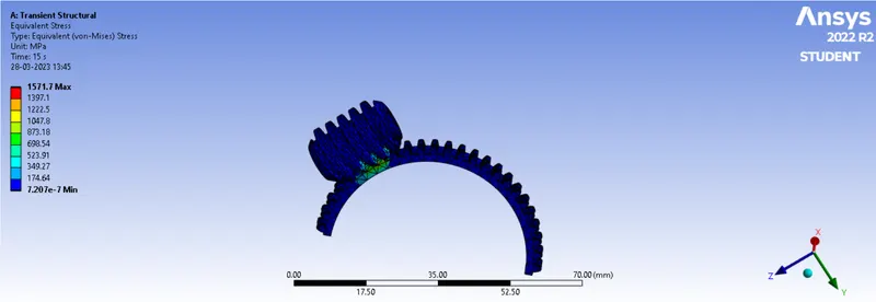
1. EQUIVALENT STRESS
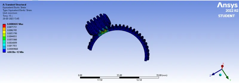
2. EQUIVALENT ELASTIC STRAIN
Total Deformation
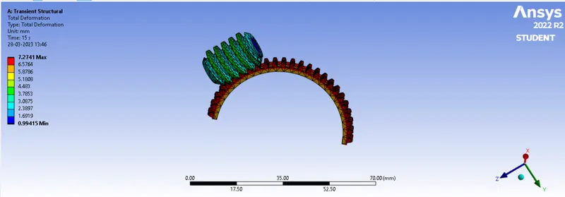
Results shows the development of high Equivalent stresses in the worm gear model and also it is varying almost periodically fluctuating from 1571.7MPa. Total deformation of about 7.27mm is seen in the following simulation when worm gear is rotated to about 750 degree angle about its axis of rotation. 0.008967 is the strain developed.