Week 8 Worm Gear Challenge
Transient Structural Analysis on the Worm Gear
Aim :
- To perform Transient Structural Analysis on the Worm Gear.
Objective :
- To define appropriate materials for the Worm Gear Model.
- To define connections between them.
- To perform mesh on the Worm Gear Model.
- To define appropriate Boundary Conditions to the Model.
- To request outputs for Total Deformation, Von-Mises Stress, Equivalent Elastic Str
Procedure :
step 1: Open the ansys workbench module and select the transient structural analysis.
step 2: Right click the geomentry tab and select import geomentry --> browse --> select the file --> open.
step 3: Now edit the geomentry in spaceclaim by splitting the gear into two component and delete one half of the gear for the case 2.
step 4: Now open the geomentry in mechanical modeller. its look like as shown in below image.
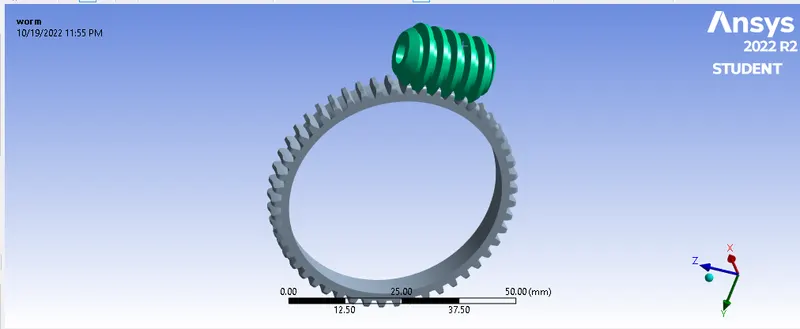
step 5: Now assign the material for both worm and gear.
stuctural steel for both warm and gear are assign.
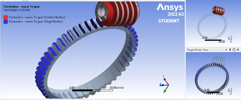
step 6: Now create a contact between the worm and gear. As shown in below image.
Now select the connection contact frictionless -Worm to gear.
insert contact set type frictionless and select contact body worm and target gear select teeth properly.
step 7: Now create revolute joint for both worm and gear.
select joint body to ground.
Insert revolute joint - Ground to gear (select inner s\f of gear face as a scope)
Insert revolute joint - Ground to worm (select inner s\f of worm face as a scope)
step 8: Now mesh the model.
- Mesh the model approriately. The element size for the meshing of this component is defolt size.
- Nodes : 12567
- Element : 5873
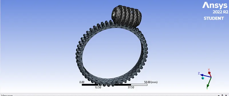 case 1
MESH FOR CASE 2
Insert method Tetrahedran for finer mesh use body sizing element size 1.85 mm for finer mesh and more accurate result.
Nodes : 14248
Element: 7400
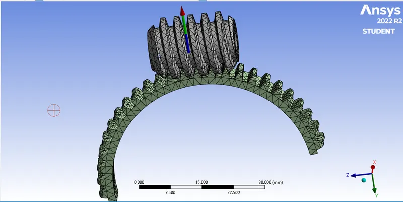 case 2
step 9: Now change the analysis settings.
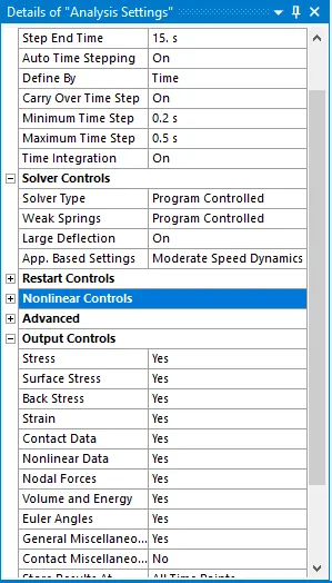
- insert number of step for simulation are 15. auto time steping on and defined by time.
- In analysis settings, initial time step is 0.2 seconds, the minimum time step is 0.2 seconds and maximum time step is 0.5 seconds Apply joint load to the worm as rotation.
- Now for results, apply equivalent stress,equivalent strain and Total deformation.
- make weak spring on and all output contro are yes. only contact miscellanies to No.
- now select step 2 to 15 and select all as case 1.
Now insert load Joint- Rotation
Joint : Revolute -Ground to Worm
DOF : Rotation Z
TYPE : Rotation
Magnitude : Tabuler Data.
NOW INSERT ALL REQUIRED RESULT CLICK TO SOLVE TO GET THE RESULT.
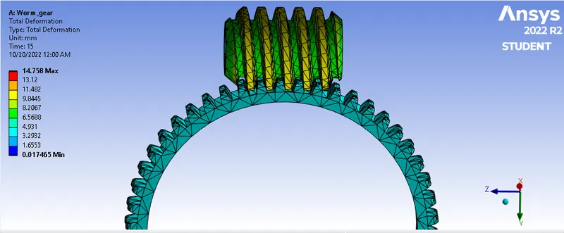
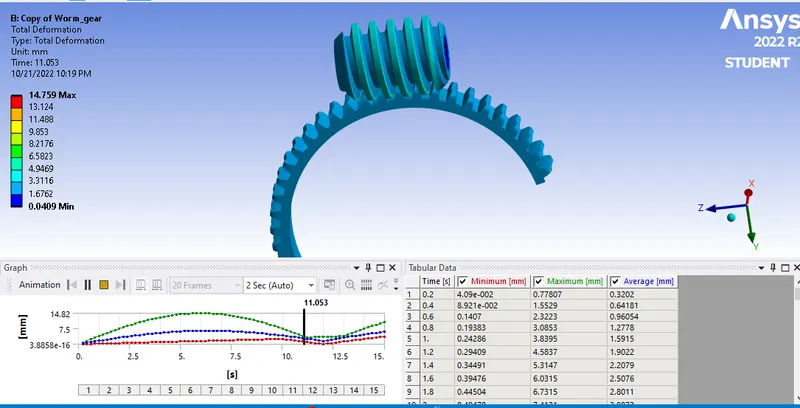
TOTAL DEFORMATION
 CASE 1
 CASE 2
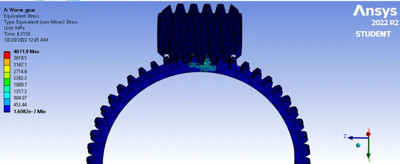
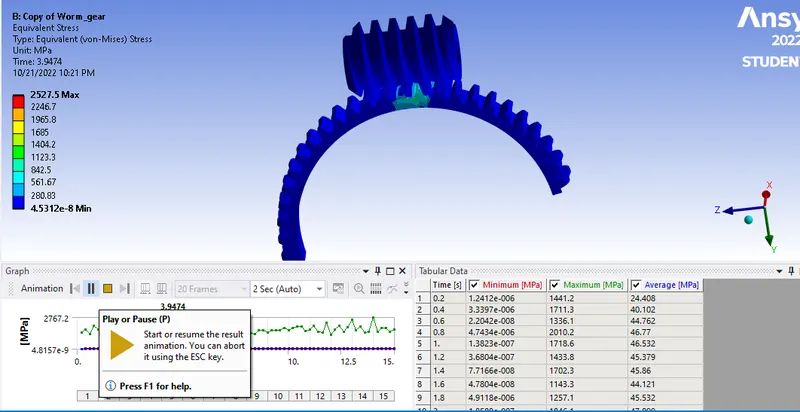
EQUIVALENT STRESS
 CASE 1
 CASE 2
EQUIVALENT STRAIN
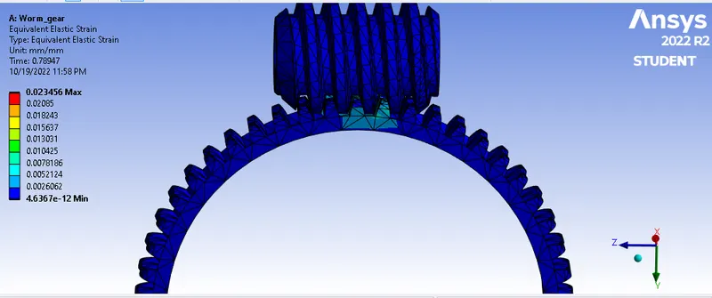 CASE 1
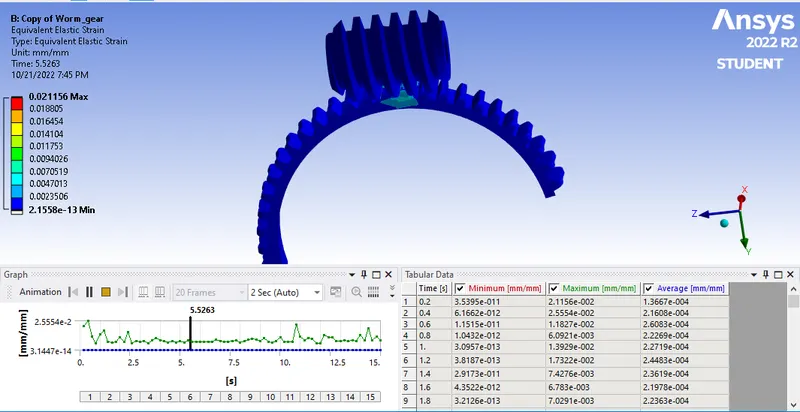 CASE 2
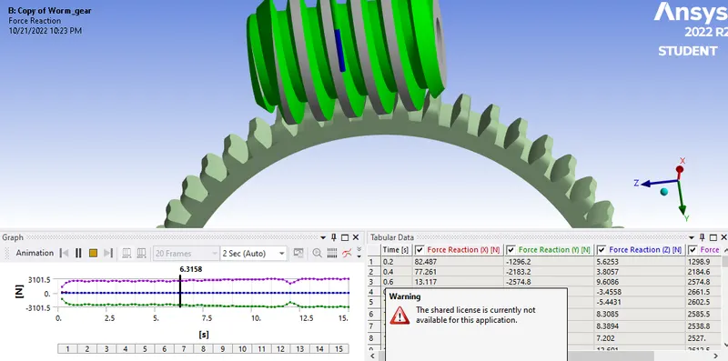
FORCE REACTION
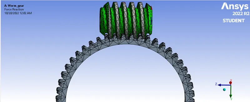 CASE 1
 CASE 2
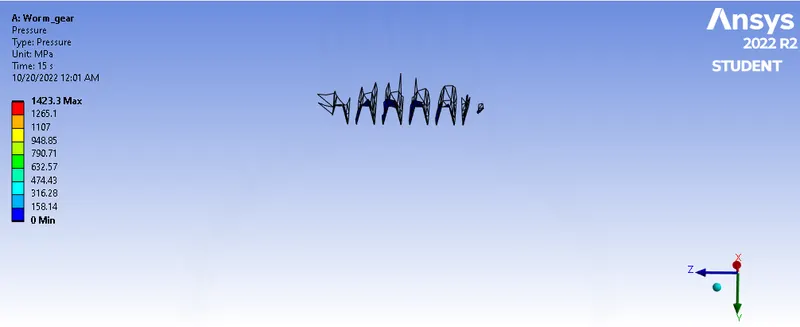
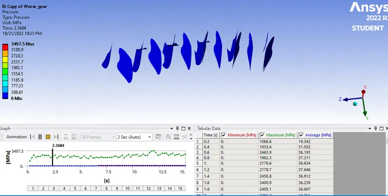
PRESSURE
 CASE 1
 CASE 2
CONCLUSION :-
find the comparasion between both case.
|
MATERIAL |
CASE 1 |
CASE 2 |
|
EQUIVALENT max STRAIN min |
0.023456 MPa 4.6367E-12 MPa |
0.015162 MPa 5.32032E-13 MPa |
|
EQUIVALENT STRESS max min |
4071.9 MPa 1.6082E-7 MPa |
2527.5 MPa 4.5312E-8 MPa |
|
TOTAL max DEFORMATION min |
14.758 MM 0.017465 MM |
14.759 MM 0.0409 MM |
|
PRESSURE MAX MIN |
1423.3 MPa 0 |
3497.5 MPa 0 |
1. The transient structural analysis on a worm gear assembly was carried out successfully.
2. The maximum value of total deformation is 14.758 mm. Observed thet Total deformation was not change in both case.
3. The maximum value of equivalent stress is developed in the teeth of the worm wheel i.e., 4071.9 MPa.
4. The maximum value of Equivalent Elastic Strain is developed in the teeth of the worm wheel i.e., 0.023456 MPa.
5. The maximum equivalent stress and strain is developed in the teeth of the worm wheel, which will eventually lead to failure hence, it is recommended to change the material of the teeth of worm wheel.