Week 8 Worm Gear Challenge
Transient Structural Analysis on a Worm gear assembly
OBJECTIVE:
To perform transient structural simulation in the given worm gear assembly using ANSYS Workbench. The following objectives have to be satisfied.
- To cut the model to half to bring it within academic limits
- The worm should be rotated to the end of the half-cut.
- The equivalent stress, equivalent elastic strain, and total deformation have to be discussed
3D model of the worm gear assembly.
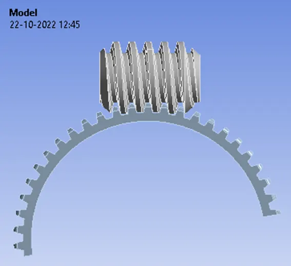
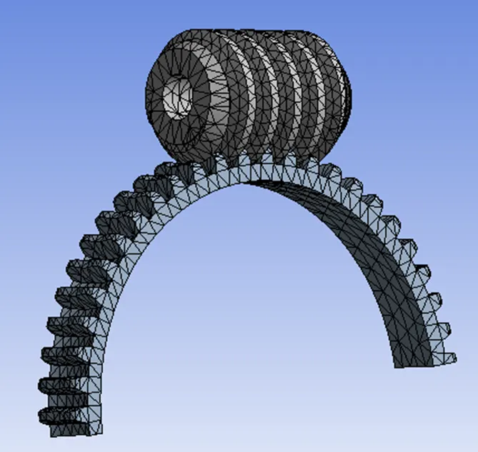
The given 3D model of the worm gear assembly is imported into SpaceClaim. It consists of a worm and worm wheel. To bring the model within the limits of the academic version and to reduce the computational time, the worm wheel is cut by half as shown in fig
Connection Details:
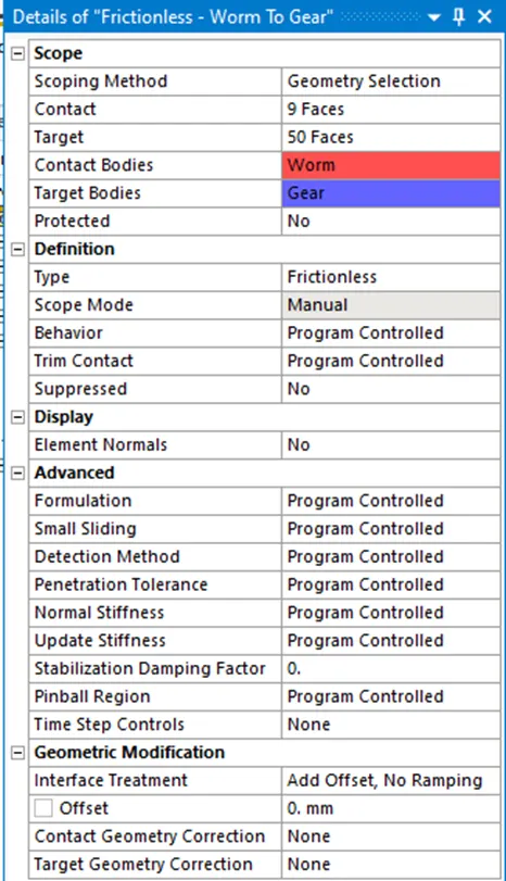
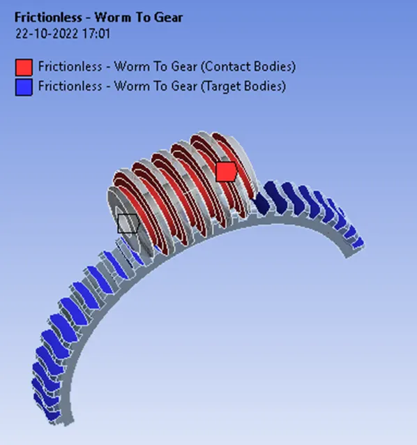
Contact details: Contact details of worm and gear assembly.
The contact between, the worm (contact body) and worm wheel (target body) is assigned as frictionless contact.
Joint Details
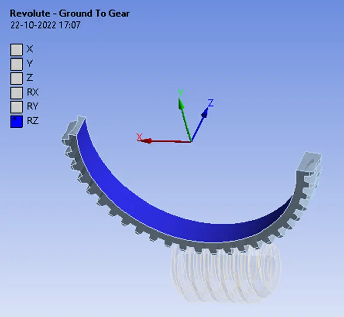
Revolute joint specified for worm wheel.
Revolute joint specified for worm.
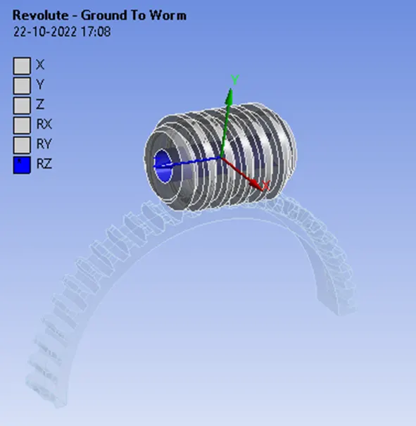
Joint details of worm gear assembly,
In order to rotate the worm, the revolute type of joint is specified along Z-axis with the connection type being body-ground. The worm wheel is specified with a revolute joint along Z-axis with the connection type being body-ground to follow the rotary motion of the worm.
Meshing
Meshing details of worm and gear assembly. The element size of the worm and gear assembly is set to 1.5 mm. The total number of nodes and elements generated are 16178 and 8359 respectively.
Note: The academic version of the software has a problem size limit of 128k nodes or elements.
Boundary Conditions
Analysis settings
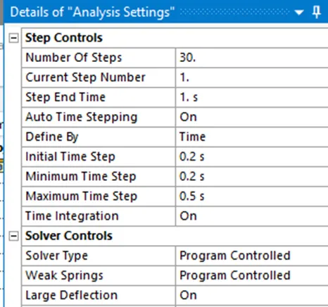
Analysis setting for step 1.
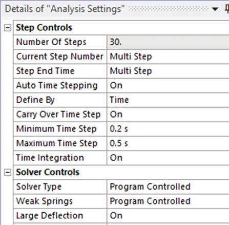
Analysis setting for steps 2 to step 30.
Boundary condition
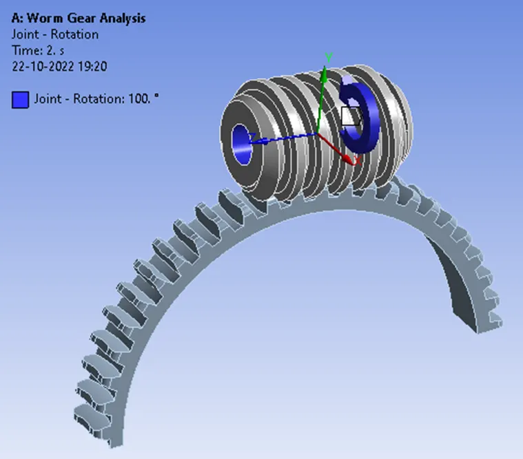
The joint load is applied to the worm.
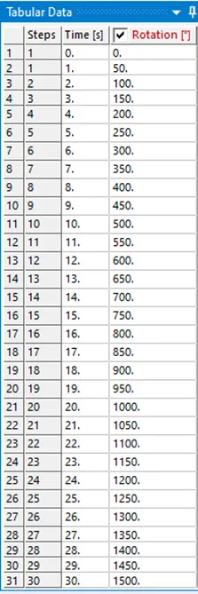
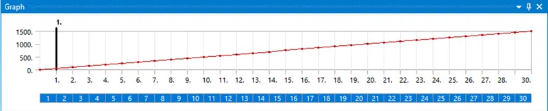
The joint load is applied to the worm to rotate it from 00 to 15000, with an increment of 500 in each step.
RESULTS AND DISCUSSIONS
Total Deformation
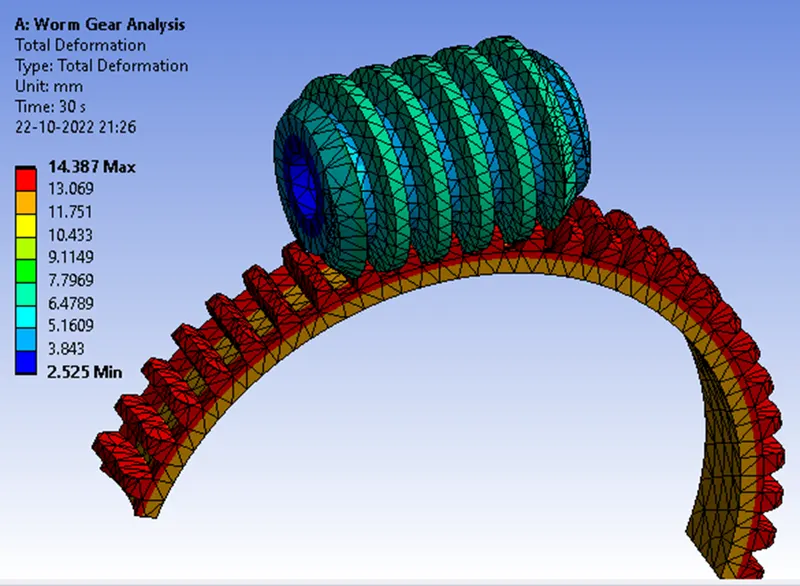
The maximum value of total deformation that occurred during the simulation of the worm gear is 14.387 mm.
Equivalent (v-m) Stress.
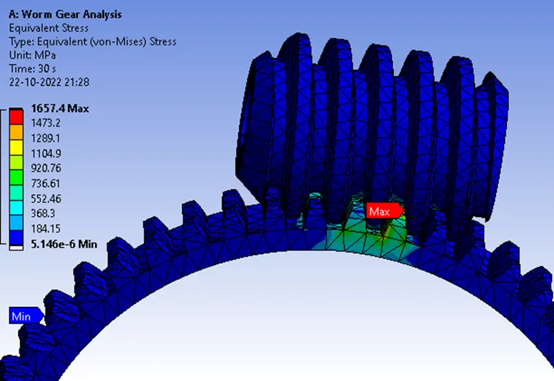
The maximum value of v-m stress is developed in the teeth of the worm wheel i.e., 1657.4 MPa which is more than the yield stress value of the material i.e., 250 MPa. Hence the teeth of the worm wheel will fail eventually during the service condition.
Equivalent Elastic Strain
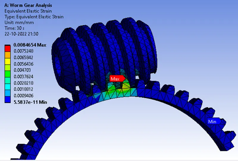
The maximum value of equivalent elastic strain is developed in the teeth of the worm wheel i.e., 0.0084654.
CONCLUSION
The maximum value of total deformation that occurred during the simulation of the worm gear is 14.387 mm.
The maximum value of v-m stress is developed in the teeth of the worm wheel i.e., 1657.4 MPa which is more than the yield stress value of the material i.e., 250 MPa. Hence the teeth of the worm wheel will fail eventually during the service condition.
The maximum value of equivalent elastic strain is developed in the teeth of the worm wheel i.e., 0.0084654.
The maximum equivalent stress and strain are developed in the teeth of the worm wheel, which will eventually lead to failure hence, it is recommended to change the material of the teeth of the worm wheel.