Week 8 - Universal Joint
1. Objective
We need to perform a transient structural analysis on a double universal joint with a spring using three different materials: Structural steel, Stainless steel and Titanium alloy. Also, these 3 materials need to be used on the joint with the springs alone
2. Case setup and execution
Case 1
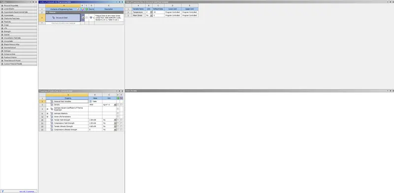
Change the material of all parts to structural steel
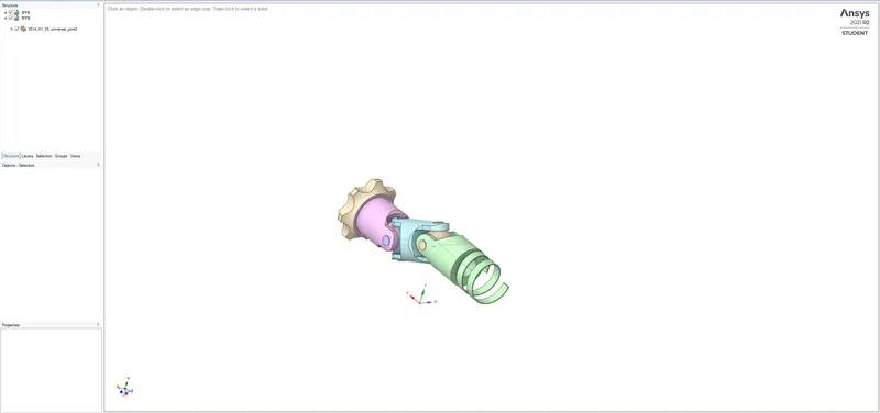
Import geometry and check for any abnormalities in SpaceClaim
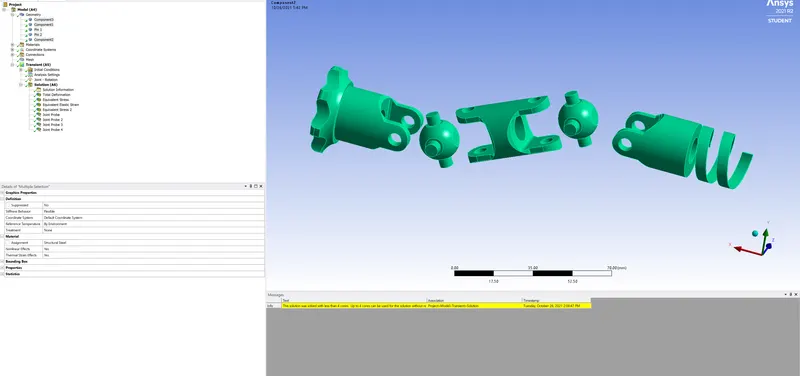
Rename the geometry parts as Component 1,2,3, Pin1 and Pin2
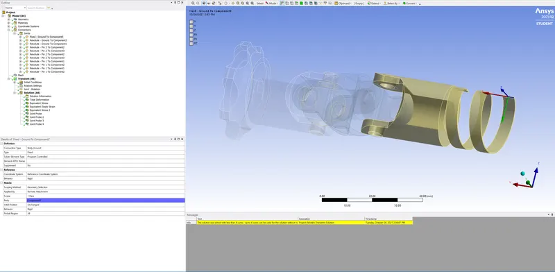
Apply fixed joint to one face of the spring
Apply revolute joint to one face of component 3
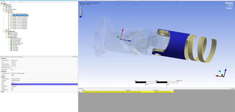
Apply revolute joint to one face of component 1
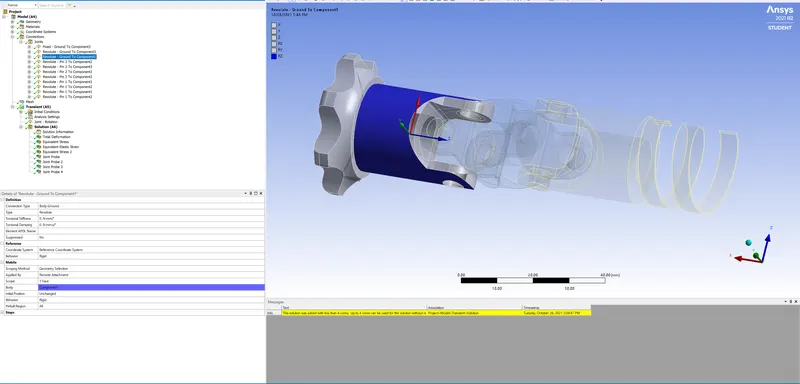
Apply Body-Body revolute joint between component 2 and pin 2
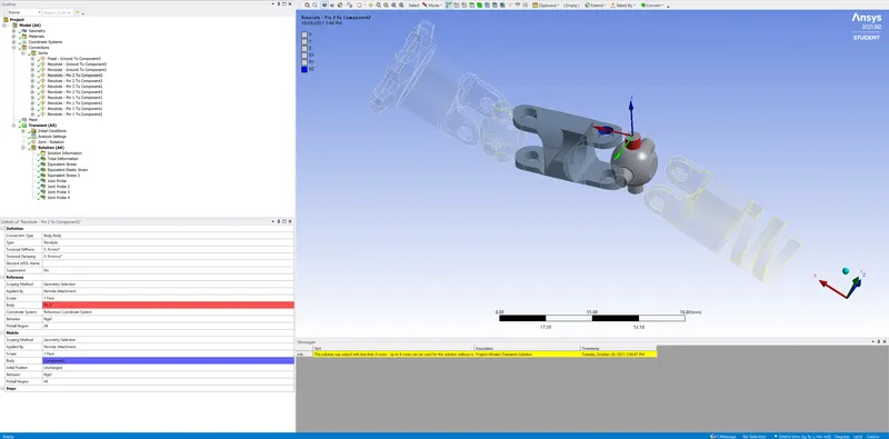
Apply revolute joint between pin2 and component 3
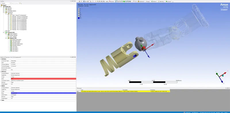
Apply revolute joint between pin2 and component 2
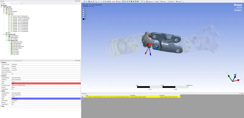
Apply revolute joint between pin2 and component 3
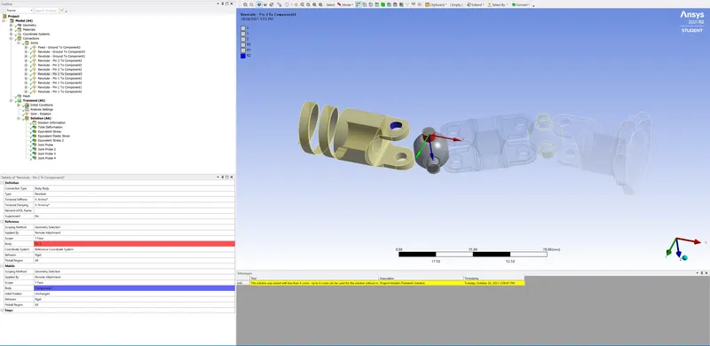
Apply revolute joint between pin1 and component 1
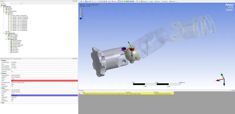
Apply revolute joint between pin 1 and component 2
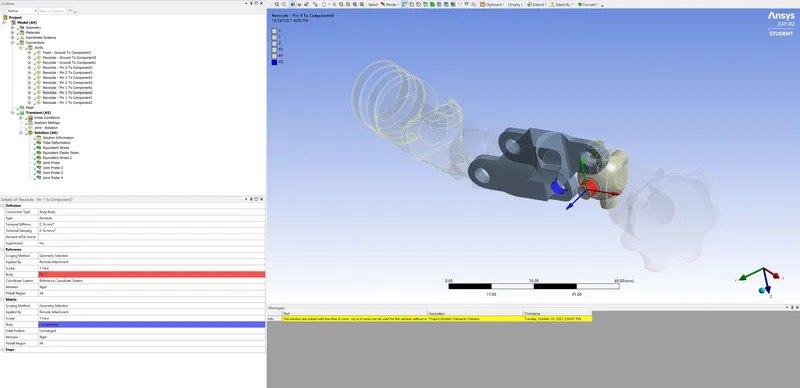
Apply revolute joint between pin1 and component 1
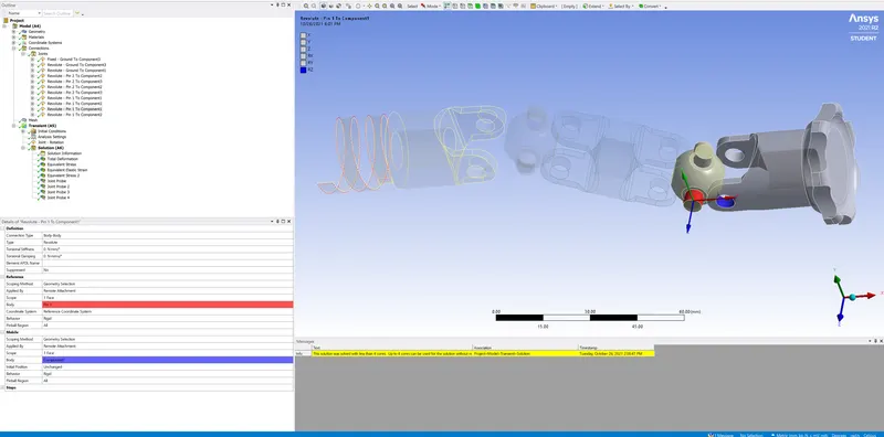
Apply revolute joint between pin1 and component 2
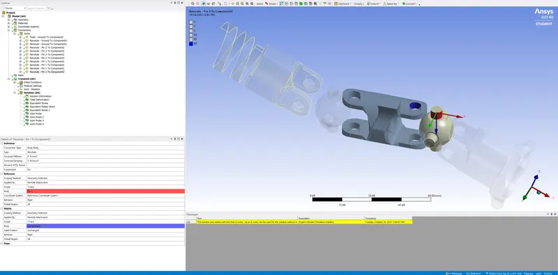
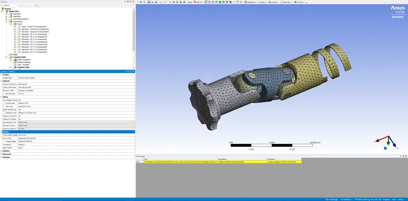
Apply mesh control with size of 2.5mm, medium smoothing and no adaptive sizing
Insert time step of 0.1s for all 5 steps and switch on all the output controls
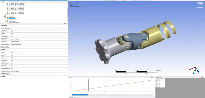
Input joint rotation for Ground to component 1 along Z-direction and magnitude in the form of a tabular data
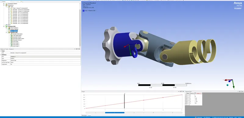
Case 2
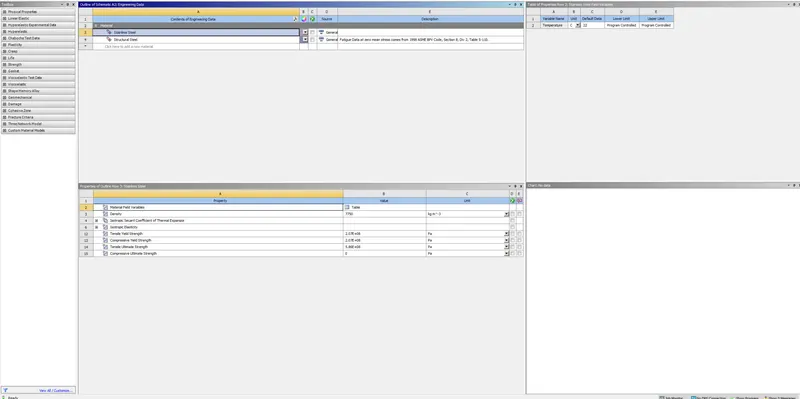
Change the material of component 3 to stainless steel and rest steps will be same as in case 1
Case 3
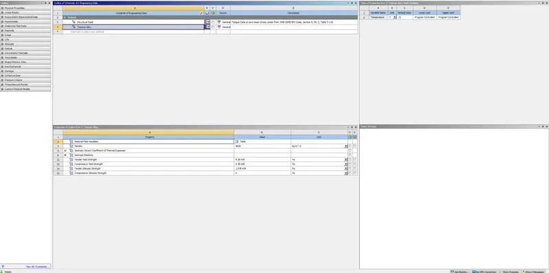
Change the material of component 3 to titanium alloy and rest steps will be same
3. Results for case 1
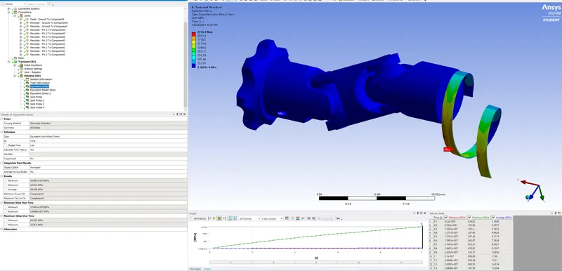
Equivalent stress for all bodies
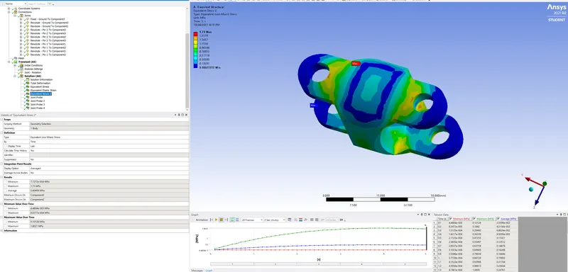
Equivalent stress for component 2
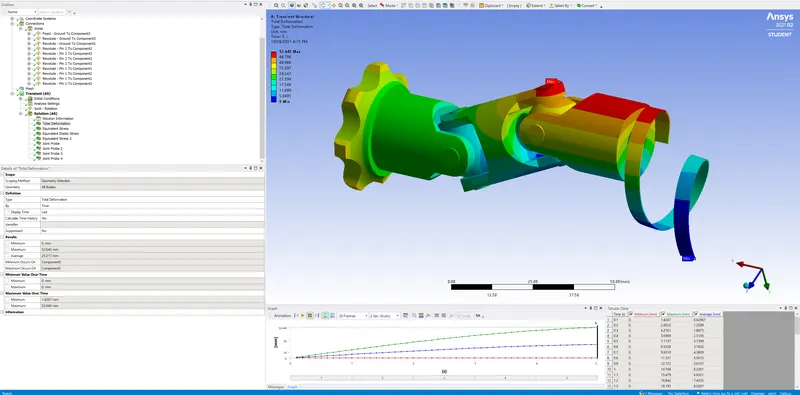
Total deformation
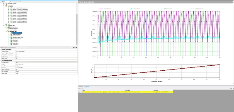
Force convergence
4. Results for case 2
Equivalent stress of all bodies
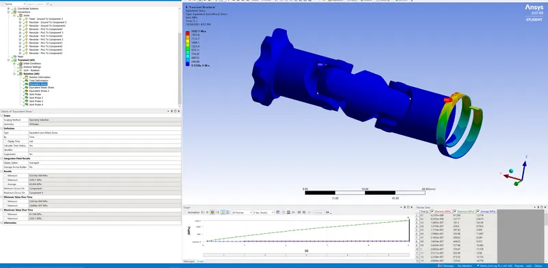
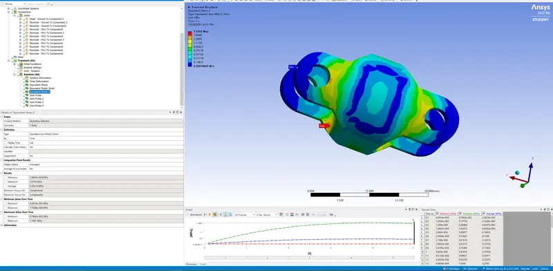
Equivalent stress of component 3
Total deformation
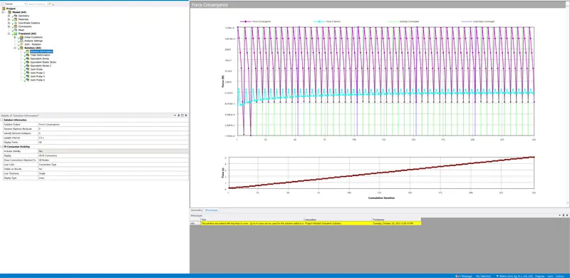
Force convergence
5. Results for case 3
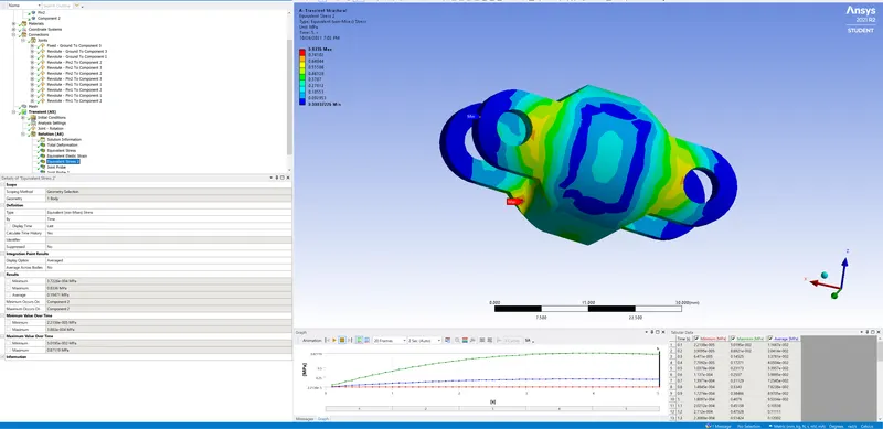
Equivalent stress for all bodies
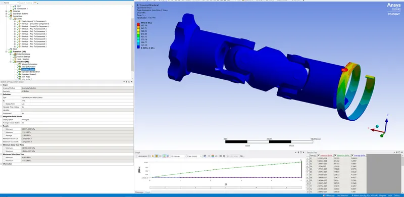
Equivalent stress for component 3
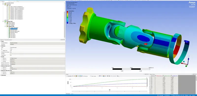
Total deformation
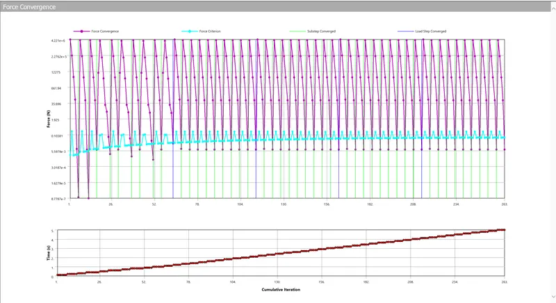
Force convergence
6. Results, conclusion and report presentation
Case 1
| Total deformation | 52.645 mm |
| Equivalent stress for all bodies | 2276.4 MPa |
| Equivalent stress for component 3 | 1.73 MPa |
Animation: https://drive.google.com/drive/folders/1ZYuOpqXovFy89iymy6Cwpit-P8BVuyPl?usp=sharing
Case 2
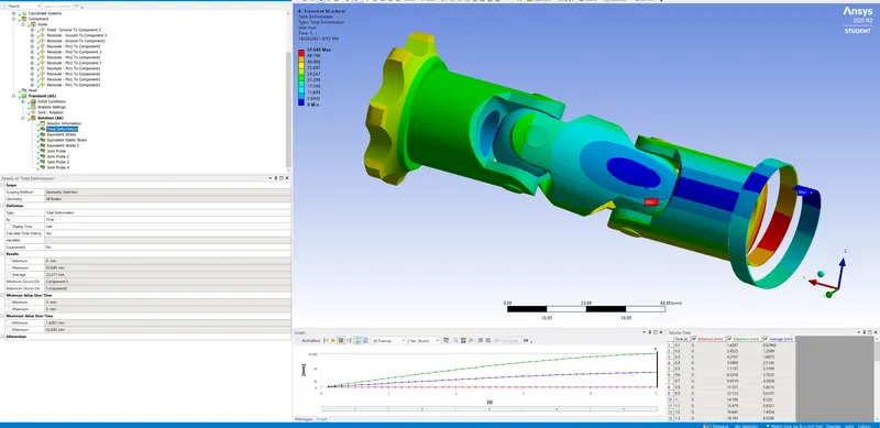
| Total deformation | 52.645 mm |
| Equivalent stress for all bodies | 2202.1 MPa |
| Equivalent stress for component 3 | 1.6703 MPa |
Animation: https://drive.google.com/drive/folders/1aNrY6X_PRh0dmtFqhMG7JKX4WrvfaGs0?usp=sharing
Case 3
| Total deformation | 52.645 mm |
| Equivalent stress for all bodies | 1110.5 MPa |
| Equivalent stress for component 3 | 0.8336 MPa |
Animation: https://drive.google.com/drive/folders/19xs-aV99We0JBzXwnWX42w1T9KZL_Wnq?usp=sharing
If we look at the above values, total deformation is the same for all cases. However, equivalent stress for all bodies and for component 3 in case 1 is higher compared to cases 2 and 3. Also, deformation for component 3 is higher at the intersection between pin joints. The equivalent stress for the spring portion is higher compared to the rest body parts.
7. Simulation files
Files are attached