Week 8 - Universal Joint
Universal Joint
OBJECTIVE: The main objective of this challenge is to perform a Transient structural Analysis on a double universal joint with a spring using three different materials such as Structural Steel, Stainless Steel and Titanium alloy. And to obtain the Equivalent stress and total deformation for all the three cases and compare them.
SOFTWARE USED: ANSYS Workbench 2022 R1 and ANSYS Mechanical for Analysis.
INTRODUCTION:
A universal joint (universal coupling, U-joint, Cardan joint, Spicer or Hardy Spicer joint, or Hooke's joint) is a joint or coupling connecting rigid rods whose axes are inclined to each other, and is commonly used in shafts that transmit rotary motion. It consists of a pair of hinges located close together, oriented at 90° to each other, connected by a cross shaft. The universal joint is not a constant-velocity joint.
CASE-1: Structural Steel Material
PROCEDURE:
1. Open the ANSYS Workbench software. Under the Analysis system select the Transient structural and wait for few seconds to pop up the window, which contains Engineering data, Geometry, Model, setup, Solution and Results.
2. Rename the Transient structural as Universal Joint.
3. Under geometry import the Long Universal Joint.
4. Update the model by right click and edit the Model for Preprocessing.
5. Wait for few seconds and ANSYS Mechanical will open as shown below.
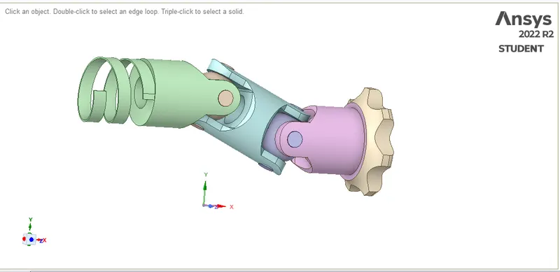
6. Assign the material to the model. Default we have structural steel. We have to change the material of springs alone and assign three different type of material for three cases. first assign structural steel, then Stainless Steel and Titanium alloy.
7. Revoiute joint: Insert a revolute joint for the gear part(Driver Yoke) and select the face as shown below. Connection type as body to ground. Make sure that the rotation axis must be oriented correctly.
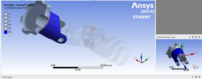
8.Revoiute joint: Insert a revolute joint for the spring part(Driven Yoke) and select the face as shown below. Connection type as body to ground. Make sure that the rotation axis must be oriented correctly.
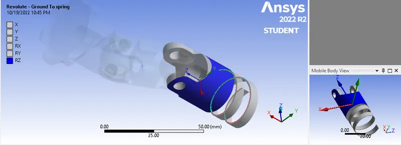
9.Revoiute joint: In universal joint we have 8 pins, that connect the driver yoke to driven yoke through a cross trunion. So we have to make the pins as revolute joint. Follow the same method for remaining pins.
Insert a revolute joint to the pin of gear part(Driver Yoke). Connection type as body to body. Make sure that the rotation axis must be oriented correctly.
10. In ANSYS automatic mesh will be performed with Default mesh size, so assign a element size of 3mm. Right click on mesh and insert a method.
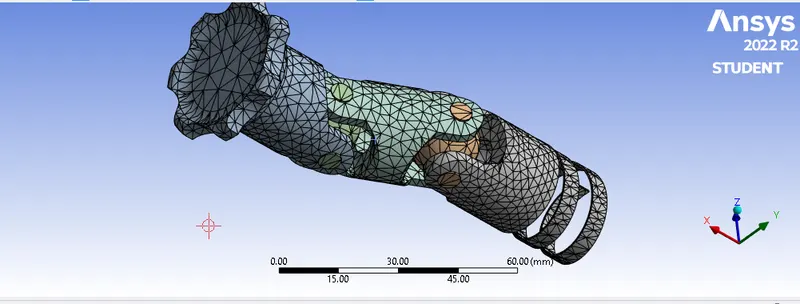
Element quality
11. Analysis settings Change no. of steps as 5, Weak spring as program controlled, large deflection on, output controls all as yes, auto time step off and select all steps and provide the time step as 0.1s.
Analysis settings
12. Joint Load for the gear part is defined by inserting a joint load and change the type as rotation, (Z) select the face as shown below for scope and magnitude of 0,30,60,90,120,150.
Joint load
13. Now request for the outputs such as equivalent stress, equivalent elastic strain, Total deformation.
14. SOLVE the solution and we can see the simulation run under soluion information.
CASE-2: Stainless Steel Material
In this case just change the material of driven yoke (spring part) as stainless steel and remaining procedure are same as mentioned in the case-1, and run the simulation.
CASE-3: Titanium alloy Material
In this case just change the material of driven yoke (spring part) as Titanium alloy and remaining procedure are same as mentioned in the case-1, and run the simulation.
SIMULATION RESULT:
case 1 : Stuctural steel
case 2 : Stainless steel
case 3 : Titanium alloy
TOTAL DIFORMATION
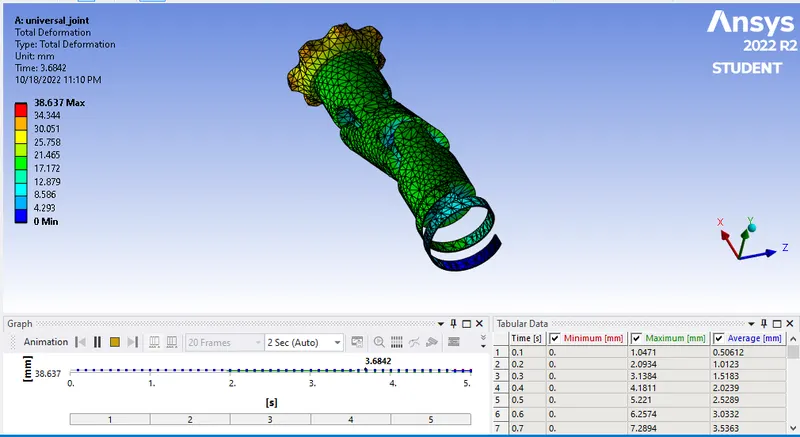 CASE 1
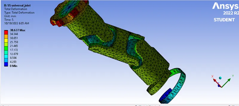 CASE 2
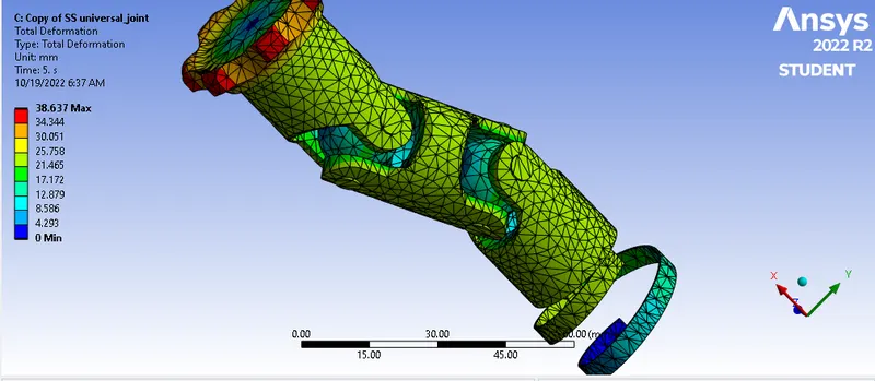 CASE 3
EQUIVALENT STRESS
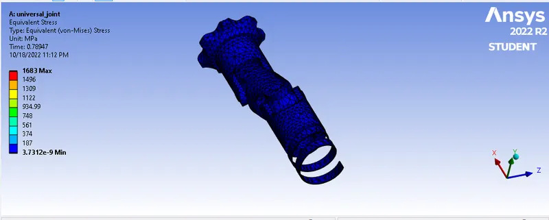 CASE 1
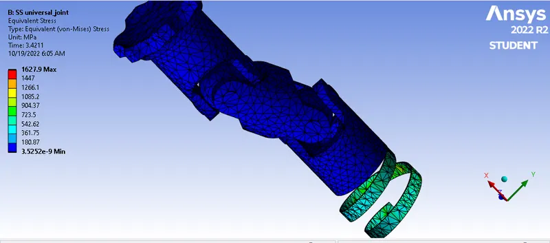 CASE 2
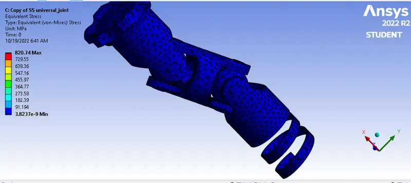 CASE 3
EQUIVALENT STRAIN
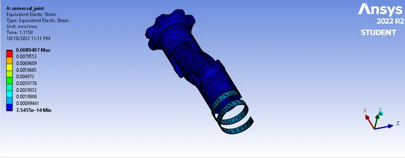 CASE 1
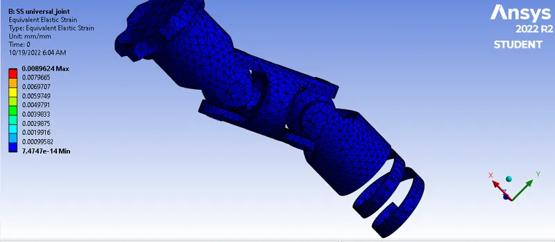 CASE 2
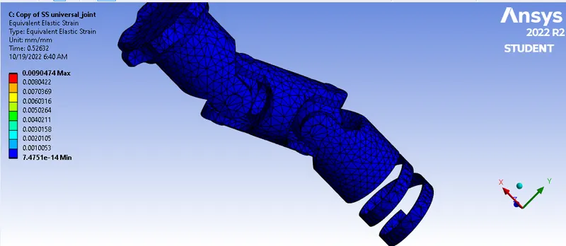 CASE 3
EQUIVALENT STRESS FOR CONNECTOR JOINT.
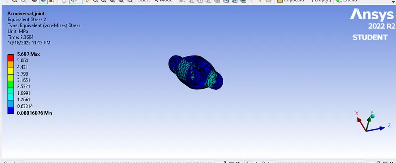 CASE 1
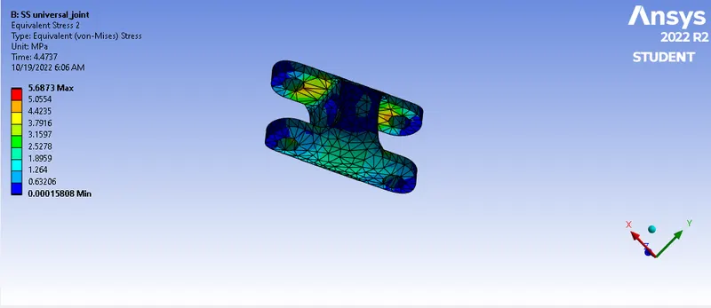 CASE 2
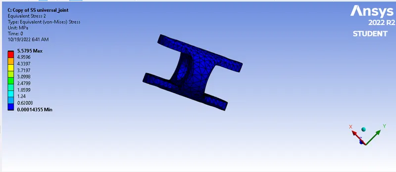 CASE 3
CONCLUSION :
Below table shows the comparisom with all three material.
|
MATERIAL |
STUCTURAL STEEL |
STAINLESS STEEL |
TITANIUM ALLOY |
|
EQUIVALENT max STRAIN min |
0.008949 7.5455E-14 |
0.0089624 7.4747E-14 |
0.0090474 7.4751E-14 |
|
EQUIVALENT STRESS max min |
1683 3.7312E-9 |
1627.9 3.5252E-9 |
820.74 3.8237E-9 |
|
TOTAL max DIFORMATION min |
38.637 0 |
38.637 0 |
38.637 0 |
|
EQUIVALENT STRESS FOR MAX CONNECTOR MIN |
5.697 0.00016076 |
5.6873 0.00015808 |
5.5795 0.00014355 |
From the above result we can conclude that the Maximum equivalent stress for stuctural steel as compared other material.
The total deformation in all the cases remains same. So we conclude that the changing of different material to a model will not effect the total deformation and it remains same for all the cases.