Simulation of a backward facing step in OpenFOAM
Simulation of Incompressible-Laminar-Viscous flow through the Backward Facing Step in OpenFOAM.
AIM: To simulate the Incompressible-Laminar-Viscous flow through the Backward facing step in OpenFOAM for the following cases
Case 1: Simulate the flow without using any grading factor (i.e., GF = 1)
Case 2: Simulate the flow with a grading factor of 0.2. The cells should be finer near the walls (including the step wall).
Also to explain the entire simulation procedure.
PROCEDURE:
Commands used in OpenFOAM to navigate and run the simulation:
1. cd = 'change directory' used to change the current directory to another directory.
2. ls = 'list' used to display the files and folders in the current directory.
3. cp = 'copy' used to copy files or folder(-r used after cp) from one location to another.
4. pwd = 'present working directory' displays the current working directory.
5. mkdir = 'make directory' creates a new folder in the current working directory.
The solver used to solve the Incompressible-Laminar-Viscous flow through the Backward facing step is icoFoam.
Process Flow:
- Creating New Folder in 'run' directory.
- Creating '0', 'constant' and 'system' folder in that new folder.
- Copying the required files in icoFoam tutorial folder for the simulation.
- Editing the 'blockMeshDict' file to create the profile.
- Updating the initial and Boundary conditions in files in '0' folder.
- Changing the values of the time step and runtime in 'controlDict' file inside the system folder.
- Running the 'blockMesh' to create 'polymesh' for the simulation.
- Running the simulation.
Step 1: To create a New Folder in the run directory.
The below image shows the procedure to create a folder in the run directory.

In the above image, 'run' is the shortcut to the run folder in the openFOAM folder.
'mkdir Test_001' creates a new folder named Test_001 in the run folder.
Step 2: Creating the '0', 'constant' and 'system' folder in that new folder.
The below image shows the procedure to create '0', 'constant' and 'system' folder in that new folder.
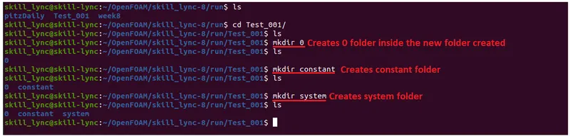
All three folders are created using the same procedure as the previous step.
Step 3: Copying the required files in icoFoam tutorial folder for the simulation.
For this simulation, the pressure and velocity of the flow are to be calculated using Euler's Scheme. All these data are present in the icoFoam tutorial simulation. The below image shows the procedure to copy the required files from the cavity folder.
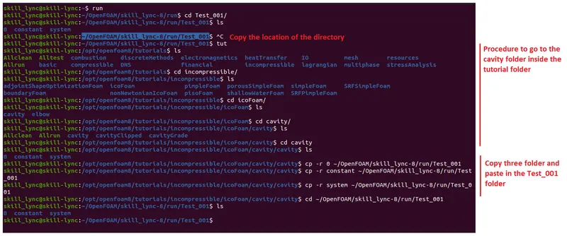
By following the above procedure all three folders are copied from the cavity folder and passed inside the Test_001 folder.
Step 4: Editing the 'blockMeshDict' file to create the profile.
The blockMeshDict is a file that has the information of the component such as dimension, faces, mesh size etc. The dimensions of the given model are used to create the mesh model. The given model is shown below
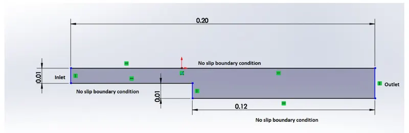
The below procedure is used to open the blockMeshDict in the system folder.

Geometry Creation:
Since 2-D simulation cannot be done in the OpenFOAM, a 3-D model is created with minimum thickness.
The above model is converted into 5 segments as below image.

The 3-D view of the model is shown below.
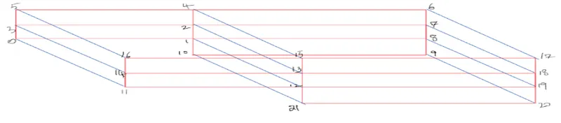
The above 3-D model has there are 20 exposed faces and 2 faces are in contact with each other. The below syntax is used to create a block.
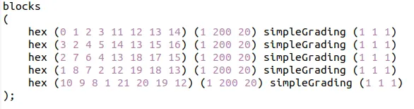
where 0-21 numbers are the vertices of the model, (1 200 20) is the mesh parameters i.e it creates 1 element in the x-direction, 200 elements in the y-direction and 20 elements in the z-direction, simpleGrading(1 1 1) used to create grading the meshing i.e to stretch the mesh to one direction.
The coordinates of those vertices are defined earlier in the blockmesh file and are shown below.
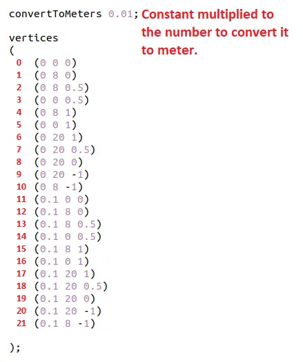
Applying Boundary Condition:
| Location | Type |
| Inlet | patch |
| Outlet | patch |
| Top and Bottom Face | wall |
| Side Faces | empty |
After adding the boundary conditions the blockmesh is tested in the terminal and checked for any errors.
The blockmesh syntax for the above model is shown.
/*--------------------------------*- C++ -*----------------------------------*
  =========                 |
  \      /  F ield         | OpenFOAM: The Open Source CFD Toolbox
   \    /   O peration     | Website:  https://openfoam.org
    \  /    A nd           | Version:  8
     \/     M anipulation  |
*---------------------------------------------------------------------------*/
FoamFile
{
    version     2.0;
    format      ascii;
    class       dictionary;
    object      blockMeshDict;
}
// * * * * * * * * * * * * * * * * * * * * * * * * * * * * * * * * * * * * * //

convertToMeters 0.01;

vertices
(
    (0 0 0)
    (0 8 0)
    (0 8 0.5)
    (0 0 0.5)
    (0 8 1)
    (0 0 1)
    (0 20 1)
    (0 20 0.5)
    (0 20 0)
    (0 20 -1)
    (0 8 -1)
    (0.1 0 0)
    (0.1 8 0)
    (0.1 8 0.5)
    (0.1 0 0.5)
    (0.1 8 1)
    (0.1 0 1)
    (0.1 20 1)
    (0.1 20 0.5)
    (0.1 20 0)
    (0.1 20 -1)
    (0.1 8 -1)

);

blocks
(
    hex (0 1 2 3 11 12 13 14) (1 200 20) simpleGrading (1 1 1)
    hex (3 2 4 5 14 13 15 16) (1 200 20) simpleGrading (1 1 1)
    hex (2 7 6 4 13 18 17 15) (1 200 20) simpleGrading (1 1 1)
    hex (1 8 7 2 12 19 18 13) (1 200 20) simpleGrading (1 1 1)
    hex (10 9 8 1 21 20 19 12) (1 200 20) simpleGrading (1 1 1)
);

edges
(
);

boundary
(
    inlet
    {
        type patch;
        faces
        (
            (0 11 14 3)
            (3 14 16 5)
        );
    }
    outlet
    {
        type patch;
        faces
        (
            (9 8 19 20)
            (8 7 18 19)
            (7 6 17 18)
        );
    }
    frontAndBack
    {
        type empty;
        faces
        (
            (0 1 2 3)
            (11 12 13 14)
            (3 2 4 5)
            (14 13 15 16)
            (2 7 6 4)
            (13 18 17 15)
            (1 8 7 2)
            (12 19 18 13)
            (10 9 8 1)
            (21 20 19 12)
        );
    }
    noSlipWalls
    {
    type wall;
    faces
    (
        (5 4 16 15)
        (4 6 17 15)
        (0 1 12 11)
        (1 10 21 12)
        (10 9 21 20)
    );
    }
);

mergePatchPairs
(
);

// ************************************************************************* //
The blockmeshDict file is altered for the second case i.e the grading factor is 0.2 i.e to create finer mesh near the walls and is shown below.
blocks
(
    hex (0 1 2 3 11 12 13 14) (80 20 1) simpleGrading (1 2 1)
    hex (3 2 4 5 14 13 15 16) (80 20 1) simpleGrading (1 0.2 1)
    hex (2 7 6 4 13 18 17 15) (120 20 1) simpleGrading (1 0.2 1)
    hex (1 8 7 2 12 19 18 13) (120 20 1) simpleGrading (1 2 1)
    hex (10 9 8 1 21 20 19 12) (120 40 1) simpleGrading (1 2 1)
);
Step 5: Updating the initial and Boundary conditions in files in '0' and 'constant' folder.
1. Updating boundary condition in pressure file.
/*--------------------------------*- C++ -*----------------------------------*
  =========                 |
  \      /  F ield         | OpenFOAM: The Open Source CFD Toolbox
   \    /   O peration     | Website:  https://openfoam.org
    \  /    A nd           | Version:  8
     \/     M anipulation  |
*---------------------------------------------------------------------------*/
FoamFile
{
    version     2.0;
    format      ascii;
    class       volScalarField;
    object      p;
}
// * * * * * * * * * * * * * * * * * * * * * * * * * * * * * * * * * * * * * //

dimensions      [0 2 -2 0 0 0 0];

internalField   uniform 0;

boundaryField
{
    inlet
    {
        type            zeroGradient;
    }

    outlet
    {
        type            fixedValue;
        value           0;
    }

    frontAndBack
    {
        type            empty;
    }
    noSlipWalls
    {
        type            zeroGradient;
    }
}

// ************************************************************************* //
2. Updating the initial and boundary condition in velocity file.
/*--------------------------------*- C++ -*----------------------------------*
  =========                 |
  \      /  F ield         | OpenFOAM: The Open Source CFD Toolbox
   \    /   O peration     | Website:  https://openfoam.org
    \  /    A nd           | Version:  8
     \/     M anipulation  |
*---------------------------------------------------------------------------*/
FoamFile
{
    version     2.0;
    format      ascii;
    class       volVectorField;
    object      U;
}
// * * * * * * * * * * * * * * * * * * * * * * * * * * * * * * * * * * * * * //

dimensions      [0 1 -1 0 0 0 0];

internalField   uniform (0 0 0);

boundaryField
{
    inlet
    {
        type            fixedValue;
        value           uniform (0 1 0);
    }

   outlet
    {
        type            zeroGradient;
    }

    frontAndBack
    {
        type            empty;
    }
    noSlipWalls
    {
        type            noSlip;
    }
}

// ************************************************************************* //
3. Updating the constants in constant folder.
/*--------------------------------*- C++ -*----------------------------------*
  =========                 |
  \      /  F ield         | OpenFOAM: The Open Source CFD Toolbox
   \    /   O peration     | Website:  https://openfoam.org
    \  /    A nd           | Version:  8
     \/     M anipulation  |
*---------------------------------------------------------------------------*/
FoamFile
{
    version     2.0;
    format      ascii;
    class       dictionary;
    location    "constant";
    object      transportProperties;
}
// * * * * * * * * * * * * * * * * * * * * * * * * * * * * * * * * * * * * * //

nu              [0 2 -1 0 0 0 0] 1.787e-6;


// ************************************************************************* //
Here Kinematic Viscosity of the fluid is defined.
Step 6: Changing the values of the time step and runtime in 'controlDict' file inside the system folder.
Runtime = 5sec.
Time Step size = 0.0001sec.
/*--------------------------------*- C++ -*----------------------------------*
  =========                 |
  \      /  F ield         | OpenFOAM: The Open Source CFD Toolbox
   \    /   O peration     | Website:  https://openfoam.org
    \  /    A nd           | Version:  8
     \/     M anipulation  |
*---------------------------------------------------------------------------*/
FoamFile
{
    version     2.0;
    format      ascii;
    class       dictionary;
    location    "system";
    object      controlDict;
}
// * * * * * * * * * * * * * * * * * * * * * * * * * * * * * * * * * * * * * //

application     icoFoam;

startFrom       startTime;

startTime       0;

stopAt          endTime;

endTime         5;

deltaT          0.0001;

writeControl    timeStep;

writeInterval   20;

purgeWrite      0;

writeFormat     ascii;

writePrecision  6;

writeCompression off;

timeFormat      general;

timePrecision   6;

runTimeModifiable true;


// ************************************************************************* //
Step 7:Running the 'blockMesh' to create 'polymesh' for the simulation.
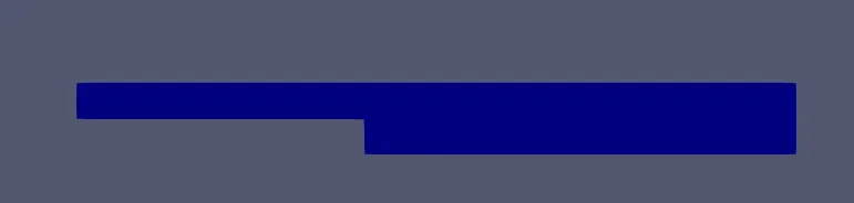
After adding the boundary conditions the blockMesh is checked for any errors and it ran without errors. To check the model 'paraFoam' is used to view the model.
The image of the mesh model is shown below.
Step 8: Running the simulation.
'icoFoam' is used to run the simulation. The simulation ran successfully without errors. In the Test_001 folder there were 2500 files excluding the '0','constant' and 'system' folder. 'paraFoam' is used to view the simulation. The image of the flow of the fluid inside a backward facing step is shown below.
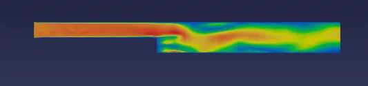
Two simulations is ran twice, at first the mesh grading was set to 1 i.e uniform mesh and in the second simulation the mesh is made finer at the boundary so that boundary layer is simulated with greater accuracy.
The image of the blockmesh of the first simulation is shown below.
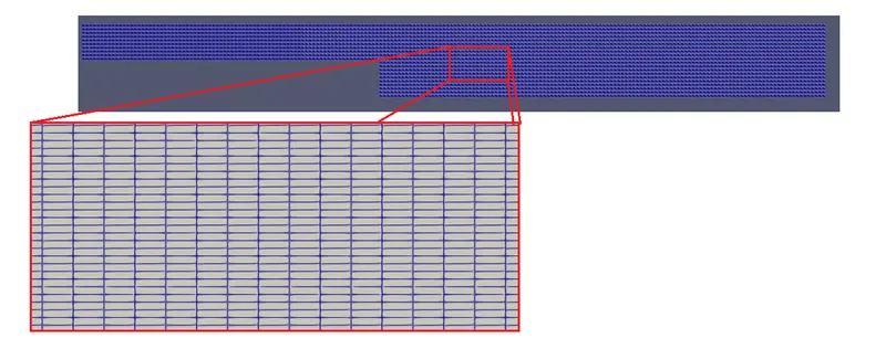
Image of Uniform Mesh model.
The image of the mesh of the second simulation is shown below.

Image of the Non Uniform Mesh Model.
RESULTS:
Both simulations ran without an error for 5 seconds and results are viewed in the ParaView. To view the results in ParaView(WSL) '.foam' file is created in the same folder and the same file is opened in the ParaView application.
Simulation 1. Uniform Mesh
The below image shows the image of the velocity flow through the backward facing step.
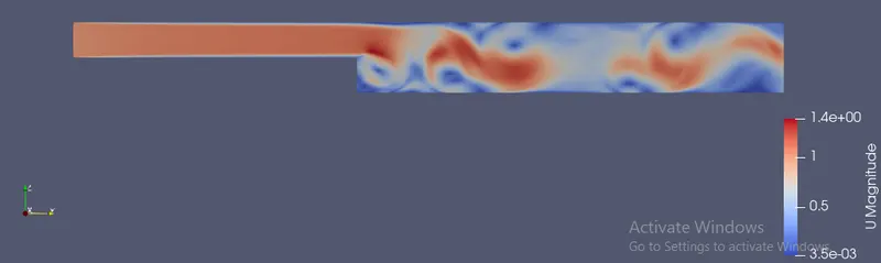
Image R.1 Velocity of Flow.
The below image shows the image of the variation of pressure inside the flow.
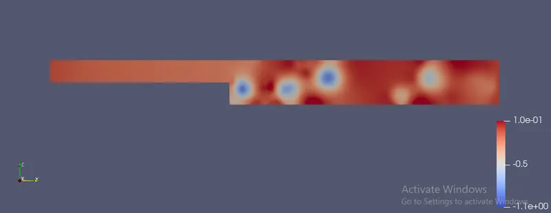
Image R.2 Pressure in the flow.
In the ParaView the graph of velocity through the flow is plotted by using the plot over the line tool and creating the Line type probe at a distance 0.085 m from the inlet.
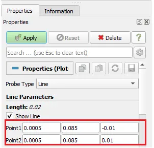
Image R.3 Plotting the Velocity profile and Pressure profile.
The below image shows the plot of Velocity Profile.
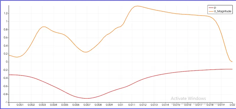
Image R.4 Velocity Profile and Pressure profile.
Due to the sudden enlargement of the cross section of flow, the flow is disturbed and the velocity at the block 5(near the backward step) is less when compared with block 3 and 4. Also the pressure is minimum at the intersetion of block 4 and 5. Due to the boundary layer effect the velocity is reduces gradually near the top surface. The pressure is not disturbed much at the top surface than the bottom surface.
From the Velocity flow image, it is seen that due to enlargement of the cross section vortices are formed and these create pressure difference in the flow. Also the pressure at the centre of vortices is lesser than the surroundings and spots are seen in the pressure image.
Simulation 2. Non Uniform Mesh
Same procedure is followed to run this simulation as well and it ran successfully.
The below image shows the image of the velocity flow through the backward facing step.
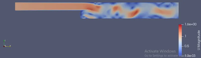
Image R.1 Velocity of Flow.
The below image shows the image of the variation of pressure inside the flow.
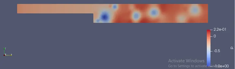
Image R.2 Pressure in the flow.
In the ParaView the graph of velocity through the flow is plotted by using the plot over the line tool and creating the Line type probe at a distance 0.085 m from the inlet.
The below image shows the plot of Velocity Profile
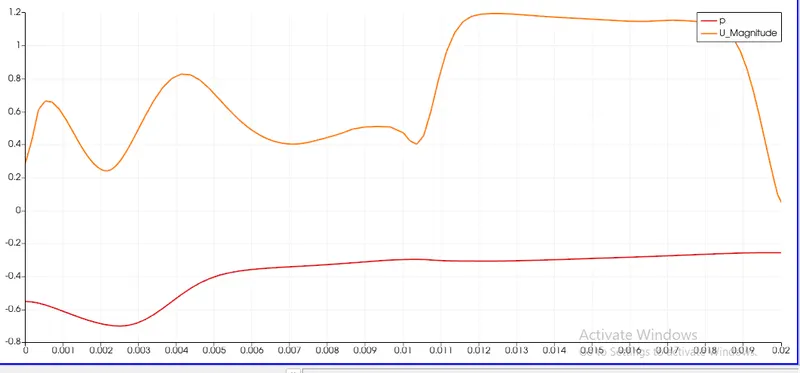
Image R.4 Velocity Profile and Pressure profile.
Due to the non uniformity in the mesh the vorticies are formed at different locations when compared with the previous simulation. And the pressure varation is more near the vorticies and there more disturbance due to the vortex formed at the backward step. By inreasing the mesh density at the boundary helps in increasing the accuracy of the formation of boundary layer.
CONCLUSION:
Incompressible-Laminar-Viscous flow through the Backward facing step in OpenFOAM is simulated in two ways, one with grading factor 1 and second with grading factor 0.2 i.e increasing the mesh density near the walls. And results are viewed in the ParaView. Form the results it is seen that the sudden enlargement of the corss section of Incompressible-Laminar-Viscous fluid flow creates vortices and these vortices move with the flow creating disturbances. Also it is seen that pressure is less at the center of the vortex when compared with the surrounding pressure. Form the two simulations, the boundary layer was well defined in the second simulation where the mesh density was more near the walls.