Week 8 - Simulation of a backward facing step in OpenFOAM
Aim: - To simulate an incompressible-laminar-viscous flow through the backward facing step geometry.
Objective: -
- Simulate incompressible laminar viscous flow through BFS geometry using solvers in OpenFoam.
- To compare the results of different grading i.e., 1 and 0.2 respectively any explaining the importance in grading/growth factor in meshing.
Mesh specifications –
Number of cells along the x direction (longer dimension) = 200
Number of cells along the longer y direction = 20;
Geometric specification: -
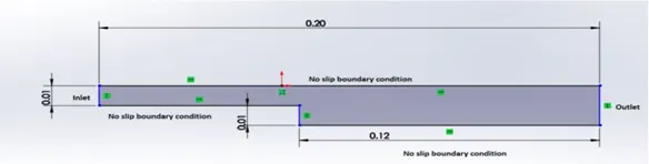
The geometric dimensions and boundary specifications for the Backward facing step (BFS) is given in below figure.
STEPS IN SIMULATION (for Grading Factor =1):
- Create a temporary directory named FOAM_RUN by copying the cavity folder from TUTORIAL in OpenFOAM.
- The cavity contains 3 folders namely ‘0’, ‘constant’ and ‘System’. O contains the initial condition information whilst constant contains the constant value used in the equations and mesh created, whereas system contains the block mesh info., control parameter and FVM schemes used on the differentials to find the solution.
- Change the directory to system change the ‘BlockMeshDict’ file so as to get desired size of blocks and the geometrical dimensions of the BFS. The change BlockMeshDict is below
/*--------------------------------*- C++ -*----------------------------------*\
  =========                 |
  \\      /  F ield         | OpenFOAM: The Open Source CFD Toolbox
   \\    /   O peration     | Website:  https://openfoam.org
    \\  /    A nd           | Version:  8
     \\/     M anipulation  |
\*---------------------------------------------------------------------------*/
FoamFile
{
    version     2.0;
    format      ascii;
    class       dictionary;
    object      blockMeshDict;
}
// * * * * * * * * * * * * * * * * * * * * * * * * * * * * * * * * * * * * * //

convertToMeters 0.01;

vertices
(
    (0 0 0)      //vertex 0
    (8 0 0)      //vertex 1
    (8 1 0)      //vertex 2
    (0 1 0)      //vertex 3
    (14 0 0)     //vertex 4
    (14 1 0)     //vertex 5
    (20 0 0)     //vertex 6
    (20 1 0)     //vertex 7
    (8 -1 0)     //vertex 8
    (14 -1 0)    //vertex 9
    (20 -1 0)    //vertex 10

    (0 0 10)      //vertex 11
    (8 0 10)      //vertex 12
    (8 1 10)      //vertex 13
    (0 1 10)      //vertex 14
    (14 0 10)     //vertex 15
    (14 1 10)     //vertex 16
    (20 0 10)     //vertex 17
    (20 1 10)     //vertex 18
    (8 -1 10)     //vertex 19
    (14 -1 10)    //vertex 20
    (20 -1 10)    //vertex 21
);

blocks
(
    hex (0 1 2 3 11 12 13 14) (200 20 1) simpleGrading (1 1 1)
    hex (1 4 5 2 12 15 16 13) (200 20 1) simpleGrading (1 1 1)
    hex (4 6 7 5 15 17 18 16) (200 20 1) simpleGrading (1 1 1)
    hex (9 10 6 4 20 21 17 15) (200 20 1) simpleGrading (1 1 1)
    hex (8 9 4 1 19 20 15 12) (200 20 1) simpleGrading (1 1 1)
);

edges
(
);

boundary
(
    inlet
    {
        type patch;
        faces
        (
            (0 3 14 11)
        );
    }
    outlet
    {
        type patch;
        faces
        (
            (6 17 18 7)
            (10 21 17 6)
        );
    }
    frontAndBack
    {
        type empty;
        faces
        (
            (0 1 2 3)
            (1 4 5 2)
            (4 6 7 5)
            (9 10 6 4)
            (8 9 4 1)

            (11 14 13 12)
            (12 13 16 15)
            (15 16 18 17)
            (20 15 17 21)
            (19 12 15 20)
        );
    }
    noslipwalls
    {
        type wall;
          faces
          (
            (2 13 14 3)
            (5 16 13 2)
            (7 18 16 5)
            (9 20 21 10)
            (8 19 20 9)
            (1 12 19 8)
            (0 11 12 1)
          );
    }
);

mergePatchPairs
(
);

// ************************************************************************* //
- here first the vertices co ordinated are entered as per dimensions.
- then the region is divided into 5 blocks and its grading and mesh information is written.
- then the different boundary such as inlet and outlet, front and back etc faces vertices are defined so as to create the structure and required meshing.
- After that the BlockMeshDict file is modified tan the controlDIct file is modified as per the requirement. The modified controlDict file is below –
/*--------------------------------*- C++ -*----------------------------------*\
  =========                 |
  \\      /  F ield         | OpenFOAM: The Open Source CFD Toolbox
   \\    /   O peration     | Website:  https://openfoam.org
    \\  /    A nd           | Version:  8
     \\/     M anipulation  |
\*---------------------------------------------------------------------------*/
FoamFile
{
    version     2.0;
    format      ascii;
    class       dictionary;
    location    "system";
    object      controlDict;
}
// * * * * * * * * * * * * * * * * * * * * * * * * * * * * * * * * * * * * * //

application     icoFoam;

startFrom       startTime;

startTime       0;

stopAt          endTime;

endTime         0.1;

deltaT          1e-5;

writeControl    timeStep;

writeInterval   20;

purgeWrite      0;

writeFormat     ascii;

writePrecision  6;

writeCompression off;

timeFormat      general;

timePrecision   6;

runTimeModifiable true;


// ************************************************************************* //
- Here the start and end of simulation is provided with the value of dt.
- here the writeinterval also write the data calculated after some specified interval as in here i.e., 20.
- The system also provides the schemes to discretise the differential equation for Finite volume control methods.
- Change the directory to 0 folder and edit the pressure and velocity files so as to set the initial and boundary conditions for them. The modified files for the pressure and velocity are:
Pressure File:
/*--------------------------------*- C++ -*----------------------------------*\
  =========                 |
  \\      /  F ield         | OpenFOAM: The Open Source CFD Toolbox
   \\    /   O peration     | Website:  https://openfoam.org
    \\  /    A nd           | Version:  8
     \\/     M anipulation  |
\*---------------------------------------------------------------------------*/
FoamFile
{
    version     2.0;
    format      ascii;
    class       volScalarField;
    object      p;
}
// * * * * * * * * * * * * * * * * * * * * * * * * * * * * * * * * * * * * * //

dimensions      [0 2 -2 0 0 0 0];

internalField   uniform 0;

boundaryField
{
    inlet
    {
        type            zeroGradient;
    }

    outlet
    {
        type            fixedValue;
        value           uniform 0;
    }

    frontAndBack
    {
        type            empty;
    }

    noslipwalls
    {
       type             zeroGradient;
    }
}

// ************************************************************************* //
Velocity file:
/*--------------------------------*- C++ -*----------------------------------*\
  =========                 |
  \\      /  F ield         | OpenFOAM: The Open Source CFD Toolbox
   \\    /   O peration     | Website:  https://openfoam.org
    \\  /    A nd           | Version:  8
     \\/     M anipulation  |
\*---------------------------------------------------------------------------*/
FoamFile
{
    version     2.0;
    format      ascii;
    class       volVectorField;
    object      U;
}
// * * * * * * * * * * * * * * * * * * * * * * * * * * * * * * * * * * * * * //

dimensions      [0 1 -1 0 0 0 0];

internalField   uniform (0 0 0);

boundaryField
{
     inlet
    {
        type            fixedValue;
        value           uniform (1 0 0);
    }

    outlet
    {
        type            zeroGradient;

    }

    frontAndBack
    {
        type            empty;
    }

    noslipwalls
    {
       type             zeroGradient;
    }
}

// ************************************************************************* //
- After required modifications we change the directory to cavity and run ‘blockMesh’ command to create the blocks and mesh for the BFS. we can check the mesh using ‘checkMesh’ command.
- Then we run the solver using ‘icoFom’ command. This will take few minutes to hours as depending upon processors computational power.
- After the solver has run, we can post process the solution in paraview using ‘paraFoam’ command.
FOR Grading Factor =0.2
The steps are similar as above other than ‘BlockMeshDict’ file is modified so as to get the required grading Factor. The ‘controlDict’ file is also been modified to reduce the run time.
the modified files are: -
BlockMeshDict:
/*--------------------------------*- C++ -*----------------------------------*\
  =========                 |
  \\      /  F ield         | OpenFOAM: The Open Source CFD Toolbox
   \\    /   O peration     | Website:  https://openfoam.org
    \\  /    A nd           | Version:  8
     \\/     M anipulation  |
\*---------------------------------------------------------------------------*/
FoamFile
{
    version     2.0;
    format      ascii;
    class       dictionary;
    object      blockMeshDict;
}
// * * * * * * * * * * * * * * * * * * * * * * * * * * * * * * * * * * * * * //

convertToMeters 0.01;

vertices
(
    (0 0 0)      //vertex 0
    (8 0 0)      //vertex 1
    (8 1 0)      //vertex 2
    (0 1 0)      //vertex 3
    (14 0 0)     //vertex 4
    (14 1 0)     //vertex 5
    (20 0 0)     //vertex 6
    (20 1 0)     //vertex 7
    (8 -1 0)     //vertex 8
    (14 -1 0)    //vertex 9
    (20 -1 0)    //vertex 10

    (0 0 10)      //vertex 11
    (8 0 10)      //vertex 12
    (8 1 10)      //vertex 13
    (0 1 10)      //vertex 14
    (14 0 10)     //vertex 15
    (14 1 10)     //vertex 16
    (20 0 10)     //vertex 17
    (20 1 10)     //vertex 18
    (8 -1 10)     //vertex 19
    (14 -1 10)    //vertex 20
    (20 -1 10)    //vertex 21
);

blocks
(
    hex (0 1 2 3 11 12 13 14) (200 20 1) simpleGrading (.2 1 1)
    hex (1 4 5 2 12 15 16 13) (200 20 1) simpleGrading (5 1 1)
    hex (4 6 7 5 15 17 18 16) (200 20 1) simpleGrading (.2 1 1)
    hex (9 10 6 4 20 21 17 15) (200 20 1) simpleGrading (.2 1 1)
    hex (8 9 4 1 19 20 15 12) (200 20 1) simpleGrading (5 1 1)
);

edges
(
);

boundary
(
    inlet
    {
        type patch;
        faces
        (
            (0 3 14 11)
        );
    }
    outlet
    {
        type patch;
        faces
        (
            (6 17 18 7)
            (10 21 17 6)
        );
    }
    frontAndBack
    {
        type empty;
        faces
        (
            (0 1 2 3)
            (1 4 5 2)
            (4 6 7 5)
            (9 10 6 4)
            (8 9 4 1)

            (11 14 13 12)
            (12 13 16 15)
            (15 16 18 17)
            (20 15 17 21)
            (19 12 15 20)
        );
    }
    noslipwalls
    {
        type wall;
          faces
          (
            (2 13 14 3)
            (5 16 13 2)
            (7 18 16 5)
            (9 20 21 10)
            (8 19 20 9)
            (1 12 19 8)
            (0 11 12 1)
          );
    }
);

mergePatchPairs
(
);

// ************************************************************************* //
controlDict:
/*--------------------------------*- C++ -*----------------------------------*\
  =========                 |
  \\      /  F ield         | OpenFOAM: The Open Source CFD Toolbox
   \\    /   O peration     | Website:  https://openfoam.org
    \\  /    A nd           | Version:  8
     \\/     M anipulation  |
\*---------------------------------------------------------------------------*/
FoamFile
{
    version     2.0;
    format      ascii;
    class       dictionary;
    location    "system";
    object      controlDict;
}
// * * * * * * * * * * * * * * * * * * * * * * * * * * * * * * * * * * * * * //

application     icoFoam;

startFrom       startTime;

startTime       0;

stopAt          endTime;

endTime         0.05;

deltaT          5e-6;

writeControl    timeStep;

writeInterval   100;

purgeWrite      0;

writeFormat     ascii;

writePrecision  6;

writeCompression off;

timeFormat      general;

timePrecision   6;

runTimeModifiable true;


// ************************************************************************* //
Results: -
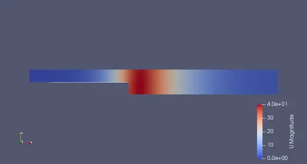
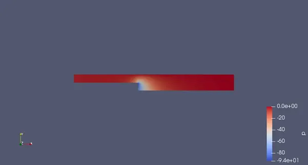
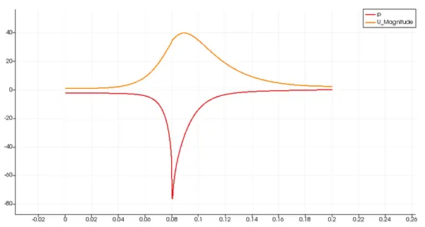
The profile at the end of 0.1 sec for GF=1 is:
Velocity profile
Pressure profile
The plot for velocity and pressure:
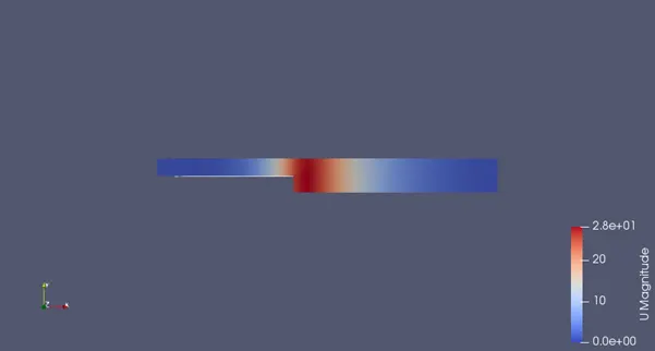
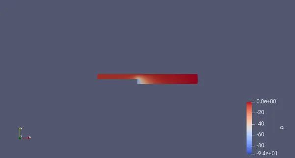
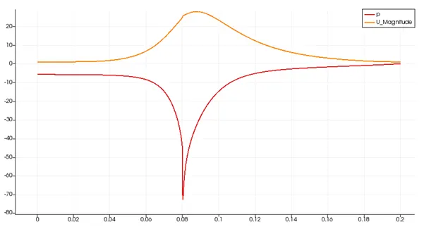
The profile at the end of 0.05 sec for GF=.2 are:
Velocity profile
Pressure profile
The plot for velocity and pressure:
Conclusion: -
The growth/grading factor here does not show difference but it is essential for meshing when some regions have more frequent and turbulent changes than others region are respectively dormant, it produces a more accurate results and without using finer mesh all through the region.
The velocity at 0.085 m from inlet after 0.1 sec is 27.623m/s.