Week 8 - Simulation of a backward facing step in OpenFOAM
Steps Involved:
- Finding adequate solver in openFoam to solve the reqired problem(icoFoam).
- Copying all the files from that folder to OpenFoam run folder so that all the predefined filed remains untouched.
- Use bolckMesh script file to create our domain and provide it proper specifications.
- In initial folder '0' edit inital parameters for velocity and pressure according to face fo the given domain.
- Find 'controlDict' file to edit start and end time for simulation.
- After running the sumulation open paraView and plot for the velocity profile at '0.085' from inlet.
- Repeating the same procedure for grading facotor 0.2 and check for any compare the results.
To start open terminal in desktop using ctrl+alt+t
- Then type tut and then type 'ls' it will give some list of folders.
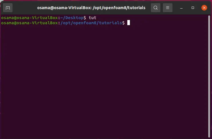
- Choose incompressible by typing "cd incompressible" and then type "ls".
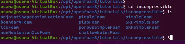
- You will again see some list of folders from which you have to choose icoFoam(which is used to solve incomprssible, laminar flow of newtonian fluids) by typing "cd icoFoam".
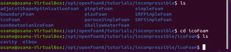
- Once you type "ls" agian you will se a folder called "cavity".Now as mentioned above you can't modify any files and folder of tutorials itself so you have to copy it in a FOAM_RUN folder.
- In order to copy it type "cp -r cavity $FOAM_RUN" and press entre.
- Now once you have a copy of all the files and folder of icoFoam you can start working on it but first change your directory to %FOAM_RUN by typing "cd $FOAM_RUN", then navigate to cavity folder and then press "ls" and change your directory to system folder.
- Using gedit command open blockMeshDict inside which we have to change our vertices point to our required geometry as follow:
The code used is as follow:
/*--------------------------------*- C++ -*----------------------------------*\ ========= | \\ / F ield | OpenFOAM: The Open Source CFD Toolbox \\ / O peration | Website: https://openfoam.org \\ / A nd | Version: 8 \\/ M anipulation | \*---------------------------------------------------------------------------*/ FoamFile { version 2.0; format ascii; class dictionary; object blockMeshDict; } // * * * * * * * * * * * * * * * * * * * * * * * * * * * * * * * * * * * * * // convertToMeters 0.01; vertices ( (0 0 0) //vertex0 (8 0 0) //vertex1 (8 0.5 0)//vertex2 (0 0.5 0)//vertex3 (8 1 0)//vertex4 (0 1 0)//vertex5 (20 1 0)//vertex6 (20 0.5 0)//vertex7 (20 0 0)//vertex8 (20 -1 0)//vertex9 (9 -1 0)//vertex10 (0 0 0.01)//vertex11 (8 0 0.01)//vertex12 (8 0.5 0.01)//vertex13 (0 0.5 0.01)//vertex14 (8 1 0.01)//vertex15 (0 1 0.01)//vertex16 (20 1 0.01)//vertex17 (20 0.5 0.01)//vertex18 (20 0 0.01)//vertex19 (20 -1 0.01)//vertex20 (8 -1 0.01)//vertex21 ); blocks ( hex (0 1 2 3 11 12 13 14) (80 20 1) simpleGrading (0.2 5 1) //block 0 hex (3 2 4 5 14 13 15 16) (80 20 1) simpleGrading (0.2 0.2 1) //block 1 hex (2 7 6 4 13 18 17 15) (120 20 1) simpleGrading (5 0.2 1) //block 2 hex (1 8 7 2 12 19 18 13) (120 20 1) simpleGrading (5 5 1) //block 3 hex (10 9 8 1 21 20 19 12) (120 20 1) simpleGrading (5 5 1) //block 4 ); edges ( ); boundary ( inlet { type patch; faces ( (0 11 14 3) (3 14 16 5) ); } outlet { type patch; faces ( (9 8 19 20) (8 7 18 19) (7 6 17 18) ); } walls { type wall; faces ( (16 15 4 5) (15 17 6 4) (10 9 20 21) (10 21 12 1) (0 1 12 11) ); } ); mergePatchPairs ( ); // ************************************************************************* //
Inside code you will also see "convertToMeters" which is used to scale our geometry to convert it into meters. - Inside the same file we have to generate our mesh without using any grading factor
here "hex" indicates the type of mesh(which in this case is hexahedral) to be created followed by faces of geometry and number of cells along x,y and z axis
"simpleGrading" is used to provide grading factor (used later). - We also need to specify the faces of inlet,outlet and walls and then save the file
Type patch is used to provide faces of inlet and outlet.
Type wall indicate the specified portion is a wall.
With all these changes we can save our file. - Next we have to modify "controlDict" folder, type "gedti controlDict", once the file is opened specify simulation time and some other parameters such as time-step "deltaT". Save the file and close it
/*--------------------------------*- C++ -*----------------------------------*\ ========= | \\ / F ield | OpenFOAM: The Open Source CFD Toolbox \\ / O peration | Website: https://openfoam.org \\ / A nd | Version: 8 \\/ M anipulation | \*---------------------------------------------------------------------------*/ FoamFile { version 2.0; format ascii; class dictionary; location "system"; object controlDict; } // * * * * * * * * * * * * * * * * * * * * * * * * * * * * * * * * * * * * * // application icoFoam; startFrom startTime; startTime 0; stopAt endTime; endTime 10; deltaT 0.005; writeControl timeStep; writeInterval 20; purgeWrite 0; writeFormat ascii; writePrecision 6; writeCompression off; timeFormat general; timePrecision 6; runTimeModifiable true; // ************************************************************************* // - Now we have to specify our boundary conditions so go back in directory by typing "cd .." then type "cd 0" and use gedit command to edit "p" and "U" files as follow:
/*--------------------------------*- C++ -*----------------------------------*\ ========= | \\ / F ield | OpenFOAM: The Open Source CFD Toolbox \\ / O peration | Website: https://openfoam.org \\ / A nd | Version: 8 \\/ M anipulation | \*---------------------------------------------------------------------------*/ FoamFile { version 2.0; format ascii; class volVectorField; object U; } // * * * * * * * * * * * * * * * * * * * * * * * * * * * * * * * * * * * * * // dimensions [0 1 -1 0 0 0 0]; internalField uniform (0 0 0); boundaryField { inlet { type fixedValue; value uniform (0.02 0 0); } outlet { type zeroGradient; } walls { type noSlip; } } // ************************************************************************* //
/*--------------------------------*- C++ -*----------------------------------*\ ========= | \\ / F ield | OpenFOAM: The Open Source CFD Toolbox \\ / O peration | Website: https://openfoam.org \\ / A nd | Version: 8 \\/ M anipulation | \*---------------------------------------------------------------------------*/ FoamFile { version 2.0; format ascii; class volScalarField; object p; } // * * * * * * * * * * * * * * * * * * * * * * * * * * * * * * * * * * * * * // dimensions [0 2 -2 0 0 0 0]; internalField uniform 0; boundaryField { inlet { type zeroGradient; } outlet { type fixedValue; value uniform 0 ; } walls { type zeroGradient; } } // ************************************************************************* // - Once done we are all set to simualte our geometry. Type "blockMesh" to generate our mesh and then type "icoFoam" this will solve our problem for the specified type
- Once the execution is over type "paraFoam", this will open a window showing our geometry. Using setober tool indicate where you want to observe your simulation and save the plot using "export" option in file.
- The last thing left is to change the grading factor to o.2
Code used for grading factor/*--------------------------------*- C++ -*----------------------------------*\ ========= | \\ / F ield | OpenFOAM: The Open Source CFD Toolbox \\ / O peration | Website: https://openfoam.org \\ / A nd | Version: 8 \\/ M anipulation | \*---------------------------------------------------------------------------*/ FoamFile { version 2.0; format ascii; class dictionary; object blockMeshDict; } // * * * * * * * * * * * * * * * * * * * * * * * * * * * * * * * * * * * * * // convertToMeters 0.01; vertices ( (0 0 0) //vertex0 (8 0 0) //vertex1 (8 0.5 0)//vertex2 (0 0.5 0)//vertex3 (8 1 0)//vertex4 (0 1 0)//vertex5 (20 1 0)//vertex6 (20 0.5 0)//vertex7 (20 0 0)//vertex8 (20 -1 0)//vertex9 (9 -1 0)//vertex10 (0 0 0.01)//vertex11 (8 0 0.01)//vertex12 (8 0.5 0.01)//vertex13 (0 0.5 0.01)//vertex14 (8 1 0.01)//vertex15 (0 1 0.01)//vertex16 (20 1 0.01)//vertex17 (20 0.5 0.01)//vertex18 (20 0 0.01)//vertex19 (20 -1 0.01)//vertex20 (8 -1 0.01)//vertex21 ); blocks ( hex (0 1 2 3 11 12 13 14) (80 20 1) simpleGrading (1 5 1) //block 0 hex (3 2 4 5 14 13 15 16) (80 20 1) simpleGrading (1 0.2 1) //block 1 hex (2 7 6 4 13 18 17 15) (120 20 1) simpleGrading (5 5 1) //block 2 hex (1 8 7 2 12 19 18 13) (120 20 1) simpleGrading (5 5 1) //block 3 hex (10 9 8 1 21 20 19 12) (120 20 1) simpleGrading (5 0.2 1) //block 4 ); edges ( ); boundary ( inlet { type patch; faces ( (0 11 14 3) (3 14 16 5) ); } outlet { type patch; faces ( (9 8 19 20) (8 7 18 19) (7 6 17 18) ); } walls { type wall; faces ( (16 15 4 5) (15 17 6 4) (10 9 20 21) (10 21 12 1) (0 1 12 11) ); } ); mergePatchPairs ( ); // ************************************************************************* //
Grading factor helps to refine our grid in some specific direction. It is simpily the ratio of width of end cell to the width of first cell
Results:
Without grading factor
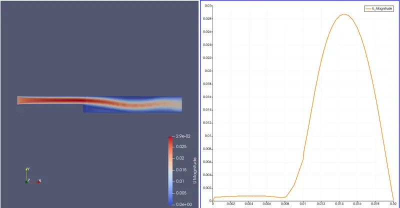
With grading factor:

Form the results above we can observe that initally results might be more accurate due some boundary layer formation and no slip condition, simulation plots nothing which might be true as well but the remaining graph remains almost the same (which does't have to be always the case), in our case the geometry was fairly simple so there might be some reason to it but overall we grading your geometry to perticuar position helps to understand or study the flow behaviour to our perticular need.