Week 8 - Simulation of a backward facing step in OpenFOAM
AIM
To simulate an incompressible-laminar-viscous flow through the backward facing step geometry and perform a transient simulation for 2 case studies as described below and compare the results.
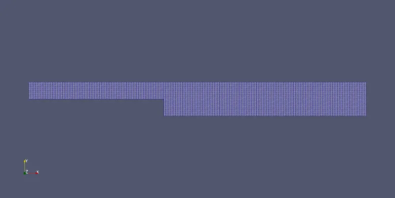
Case 1 - Simulate the flow without using any grading factor (i.e., GF = 1)
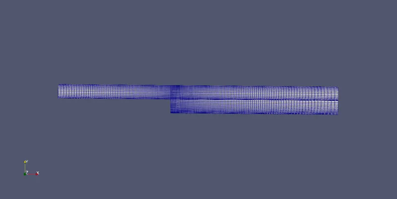
Case 2 - Simulate the flow with grading factor of 0.2. The cells should be finer near the walls (includig the step wall).
Mesh specification
- Number of cells along the x direction (longer dimension) = 200
- Number of cells along the longer y direction = 20
Boundary condition specification
The domain specifications are provided in the following figure.
Desired output
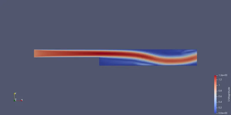
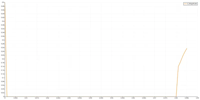
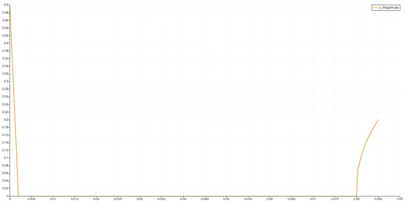
- To measure the velocity profile at 0.085 m from the inlet of the geometry for both case studies and compare using the plot over line tool.
- Also explain why Grading/Growth factor is essential for meshing.
EXPLAINATION
The necessary simulations for this study are performed using the 'icoFoam' solver in OpenFOAM and post-processed in 'ParaView'. In this work, I have chosen two different grading factors as the element size near walls has a significant effect on the accuracy of the solution. Fine mesh near the walls could improve the accuracy of results, but on the same hand, it increases the computational time required to do the simulation. Coarse mesh leads to inconsistent results and can cause convergence problems during the simulation process. However, the time required to complete the simulation is less due to the coarse meshing. So, for both finer or coarser mesh, there are some advantages and disadvantages. Here comes the role of mesh grading factor, which helps by allocating finer mesh near-wall regions or the regions where the most prominent changes w.r.t. flow parameters are going on; without sacrificing with the results. Also, the time required to complete the simulation will be less.
The Grading factor is given as the ratio of the size of the end cell to the size of the starting cell. It basically refers to the technique called ‘mesh stretching’. In this technique, the mesh is stretched to one side of the wall and is very helpful for computing efficiency.
Grading factor, f = (size of the end cell)/(size of the starting cell)
Following are the basic steps followed to perform the simulation for both the cases -
- After opening the ‘terminal’ window in the Linux operating system such as ubuntu, use ‘tut’ keyword to view the inbuilt tutorials in OpenFOAM and ‘ls’ command to view the contents in the tutorials directory.
- Select ‘icoFoam’ solver as we are simulationg transient incompressible flow.
- By typing ‘ls’ we can see the all the directories available in the icoFoam solver and choose the ‘cavity’ directory.
- Now to edit and run this tutorial, copy this tutorial to $FOAM_RUN directory using ‘cd –r cavity/ $FOAM_RUN /'. ‘$FOAM_RUN’ is the directory that OpenFOAM uses to run and save the simulations.
- Next, to get into the run directory, type the command ‘run’
- We now see files like ‘0’,’blockMeshDict’, ‘controlDict’, ‘fvschemes’, ‘fvSolution’ and we need to edit these files according to our problem specifications.
- First, edit the ‘blockMeshDict’ file to specify geometry, meshing, and boundary conditions for our problem. Start with mesh grading factor, f=1.
- In the same manner, edit the ‘controlDict’ file and provide the values like start time, end time, delta t, time interval, etc. The value of ‘delta t’ is chosen in a way that the Courant number should be less than 1.
- Next we get inside the ‘0’ directory where there are fluid properties are found such ‘p’ and ‘U’ text files. Edit them according to the problem.
- Next step is to edit 'transportProperties' file inside the 'constant' directory.
- After all the necessary editing, use ‘blockMesh’ command to get the desired geometry with mesh and boundary conditions. To check the mesh for any errors, use ‘checkMesh’ command.
- Now to run the simulation use the ‘icoFoam’ command and then use ‘paraFoam’ to launch ParaView for post-processing.
- Measure the velocity profile at 0.085m from the inlet of geometry and to get the plot for velocity use the ‘plot over line’ option, which can be availed from the ‘filters’ section of paraview.
- Repeat the above steps for a grading factor of 0.2
Case-1
Editing 'blockMeshDict' file -
/*--------------------------------*- C++ -*----------------------------------*\
  =========                 |
  \\      /  F ield         | OpenFOAM: The Open Source CFD Toolbox
   \\    /   O peration     | Website:  https://openfoam.org
    \\  /    A nd           | Version:  10
     \\/     M anipulation  |
\*---------------------------------------------------------------------------*/
FoamFile
{
    format      ascii;
    class       dictionary;
    object      blockMeshDict;
}
// * * * * * * * * * * * * * * * * * * * * * * * * * * * * * * * * * * * * * //

convertToMeters 0.01;

vertices
(
    (0 0 0)
    (8 0 0)
    (8 0.5 0)
    (0 0.5 0)
    (8 1 0)
    (0 1 0)
    (20 1 0)
    (20 0.5 0)
    (20 0 0)
    (20 -1 0)
    (8 -1 0)
    (0 0 0.1)
    (8 0 0.1)
    (8 0.5 0.1)
    (0 0.5 0.1)
    (8 1 0.1)
    (0 1 0.1)
    (20 1 0.1)
    (20 0.5 0.1)
    (20 0 0.1)
    (20 -1 0.1)
    (8 -1 0.1)
);

blocks
(
    hex (0 1 2 3 11 12 13 14) (80 10 1) simpleGrading (1 1 1)
    hex (3 2 4 5 14 13 15 16) (80 10 1) simpleGrading (1 1 1)
    hex (2 7 6 4 13 18 17 15) (120 10 1) simpleGrading (1 1 1)
    hex (1 8 7 2 12 19 18 13) (120 10 1) simpleGrading (1 1 1)
    hex (10 9 8 1 21 20 19 12) (120 20 1) simpleGrading (1 1 1)
);

boundary
(
    inlet
    {
        type patch;
        faces
        (
            (0 11 14 3)
            (3 14 16 5)
        );
    }
    outlet
    {
        type patch;
        faces
        (
            (9 8 19 20)
            (8 7 18 19)
            (7 6 17 18)
        );
    }
    frontAndBack
    {
        type empty;
        faces
        (
            (0 3 2 1)
            (3 5 4 2)
            (2 4 6 7)
            (1 2 7 8)
            (10 1 8 9)
            (11 12 13 14)
            (14 13 15 16)
            (13 18 17 15)
            (12 19 18 13)
            (21 20 19 12)
        );
    }
    NoSlipWalls
    {
        type wall;
        faces
        (
            (16 15 4 5)
            (15 17 6 4)
            (10 21 12 1)
            (11 0 1 12)
            (21 10 9 20)
        );
    }
);


// ************************************************************************* //
Editing 'controlDict' file for the 1st case -
/*--------------------------------*- C++ -*----------------------------------*\
  =========                 |
  \\      /  F ield         | OpenFOAM: The Open Source CFD Toolbox
   \\    /   O peration     | Website:  https://openfoam.org
    \\  /    A nd           | Version:  10
     \\/     M anipulation  |
\*---------------------------------------------------------------------------*/
FoamFile
{
    format      ascii;
    class       dictionary;
    location    "system";
    object      controlDict;
}
// * * * * * * * * * * * * * * * * * * * * * * * * * * * * * * * * * * * * * //

application     icoFoam;

startFrom       startTime;

startTime       0;

stopAt          endTime;

endTime         0.5;

deltaT          1e-04;

writeControl    timeStep;

writeInterval   20;

purgeWrite      0;

writeFormat     ascii;

writePrecision  6;

writeCompression off;

timeFormat      general;

timePrecision   6;

runTimeModifiable true;


// ************************************************************************* //
Editing the '0' directory files for 'u' and 'p' variables for the 1st case -
/*--------------------------------*- C++ -*----------------------------------*\
  =========                 |
  \\      /  F ield         | OpenFOAM: The Open Source CFD Toolbox
   \\    /   O peration     | Website:  https://openfoam.org
    \\  /    A nd           | Version:  10
     \\/     M anipulation  |
\*---------------------------------------------------------------------------*/
FoamFile
{
    format      ascii;
    class       volVectorField;
    object      U;
}
// * * * * * * * * * * * * * * * * * * * * * * * * * * * * * * * * * * * * * //

dimensions      [0 1 -1 0 0 0 0];

internalField   uniform (0 0 0);

boundaryField
{
    inlet
    {
        type            fixedValue;
        value           uniform (1 0 0);
    }

    outlet
    {
        type		zeroGradient;
    }

    NoSlipWalls
    {
        type            noSlip;
    }

    frontAndBack
    {
        type            empty;
    }
}

// ************************************************************************* //
/*--------------------------------*- C++ -*----------------------------------*\
  =========                 |
  \\      /  F ield         | OpenFOAM: The Open Source CFD Toolbox
   \\    /   O peration     | Website:  https://openfoam.org
    \\  /    A nd           | Version:  10
     \\/     M anipulation  |
\*---------------------------------------------------------------------------*/
FoamFile
{
    format      ascii;
    class       volScalarField;
    object      p;
}
// * * * * * * * * * * * * * * * * * * * * * * * * * * * * * * * * * * * * * //

dimensions      [0 2 -2 0 0 0 0];

internalField   uniform 0;

boundaryField
{
    inlet
    {
        type            zeroGradient;
    }

    outlet
    {
        type            fixedValue;
	  value		uniform 0;
    }

    NoSlipWalls
    {
        type            zeroGradient;
    }

    frontAndBack
    {
        type		empty;
    }

}

// ************************************************************************* //
Finally edit the physical properties
/*--------------------------------*- C++ -*----------------------------------*\
  =========                 |
  \\      /  F ield         | OpenFOAM: The Open Source CFD Toolbox
   \\    /   O peration     | Website:  https://openfoam.org
    \\  /    A nd           | Version:  10
     \\/     M anipulation  |
\*---------------------------------------------------------------------------*/
FoamFile
{
    format      ascii;
    class       dictionary;
    location    "constant";
    object      physicalProperties;
}
// * * * * * * * * * * * * * * * * * * * * * * * * * * * * * * * * * * * * * //

nu              [0 2 -1 0 0 0 0] 1.81e-05;


// ************************************************************************* //
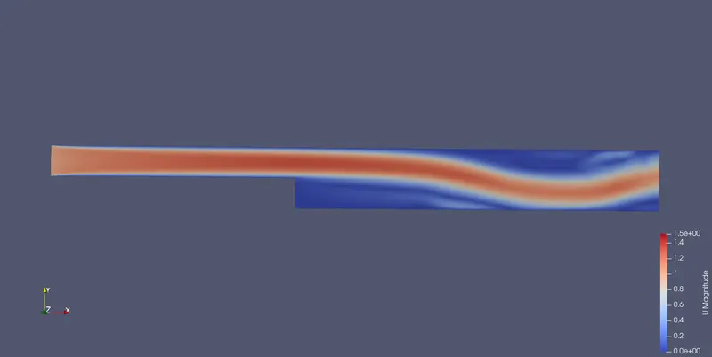
Output from ParaView -
Velocity contour plot
Velocity profile at 0.085 m from the inlet of the geometry
Case-2 - Here there is only a need to edit the 'blocks' section in the ''blockMeshDict'' file. Rest all other files remain the same.
blocks
(
    hex (0 1 2 3 11 12 13 14) (80 10 1) simpleGrading (0.2 10 1)
    hex (3 2 4 5 14 13 15 16) (80 10 1) simpleGrading (0.2 0.2 1)
    hex (2 7 6 4 13 18 17 15) (120 10 1) simpleGrading (10 0.2 1)
    hex (1 8 7 2 12 19 18 13) (120 10 1) simpleGrading (10 10 1)
    hex (10 9 8 1 21 20 19 12) (120 20 1) simpleGrading (10 10 1)
); 
Output from ParaView -
Velocity contour plot
Velocity profile at 0.085 m from the inlet of the geometry
- Explain why Grading/Growth factor is essential for meshing.
The grading or growth factor is essential for meshing because it enables accurate representation of complex phenomena, efficient allocation of computational resources, adaptability to evolving solutions, and optimization for specific physical behavior. By using an appropriate grading factor, the mesh can be refined in critical regions, ensuring accuracy while maintaining computational efficiency.
CONCLUSION
- All the steps followed to perform the above simulation have been discussed in detail. The case study has been carried out for two different grading factors.
- Not much of the difference could be spoted from the above plots, but one can notice that as the mesh grading factor decreases, a better boundary layer separation could be observed. This is because of the fact that as the grading factor decreases, more data is captured resulting in more detailed and accurate results. The details of the flow within the boundary layer are very important for many problems and hence it is advisable to have a lower mesh grading factor where important flow characteristics are to be captured.