Week 8 - Simulation of a backward facing step in OpenFOAM
Aim : Simulate flow in Backward Facing Step geometry in OpenFoam.Perform two case study for grading factor of 1 and other with grading factor with 0.2 .
Desired output
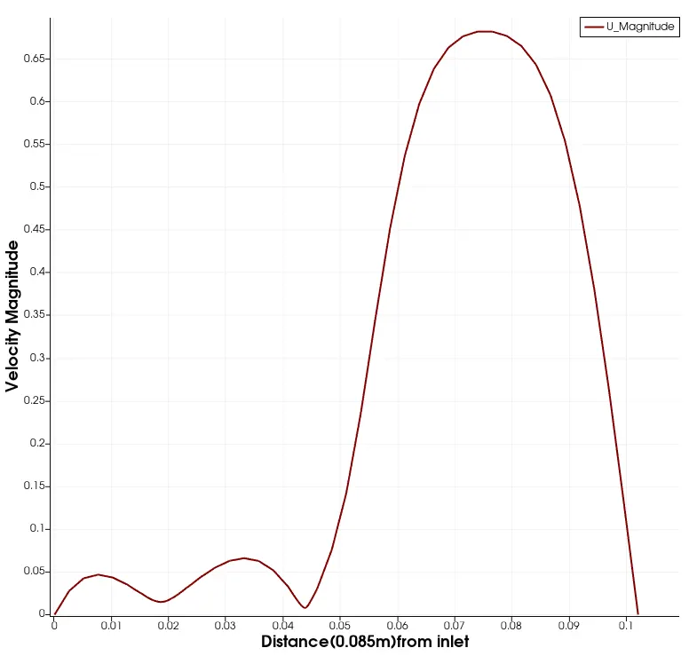
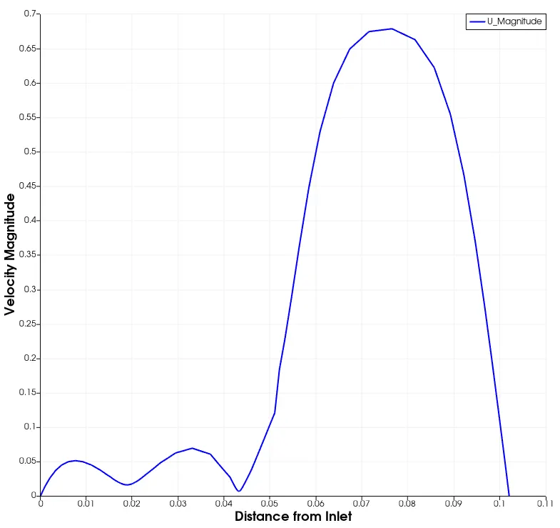
- Measure the velocity profile at 0.085 m from the inlet of the geometry for both case studies and compare. You can use the plot over line tool for this.
- Explain why Grading/Growth factor is essential for meshing.
Thoery :
OpenFoam is a open source software for the CFD.It gives users the freedom to modify and post-process result.It has an extensive features to solve anything from complex fluid flows onvolving chemical reactions,turbulence and heat transfer,solid mechanics and more.OpenFoam works on C++ launguage and it is a Finite Volume Method Solver.It gives direct access to source code to customize CFD solvers with more than 80 different solvers and various tutorials.
Backward Facins Step flow is represents flow seperation which can be seen in airfoils,spoilers,high angle of attacks,vehicles like car and boats and many more.After the seperation we can see recirculation zones to be created and reattachement process that depends on the BFS geometry.The is laminar from the inlet upto the step as the flow crosses the step the flow detaches and vortex are seen to be created.In our case we have undertake Laminar Incompressible Viscous flow for the simulation, the simulation is carried out for 0.8s.The flow is simulated using OpenFoam icoFoam solver that supports the same fluid characteristics.
Procedure :First to make changes in the cavity tutorial that is found inside the incompressible folder follow these steps.
1.Open Ubuntu in the terminal and type tut short for tutorial and to view the list of folders type 'ls' to view the folders.

2.To access the incompressible folder from the list of tutorials type 'cd' and then type the folder name that you want to access: cd incompressible and then type ls to list the folders inisde the incopressible folder.

3.Access the icoFoam folder and view the list there we can see two folders of cavity and elbow folder these are the cases that uses the icoFoam solver.Go inside the cavity folder and copy the cavity directory in the run folder and name as the backward _step .To caopy the directory use the cp -r command followed by the source file,then the folder where you want to copy the folder then /new name for the copied folder,i.e : cp -r cavity $FOAM_RUN/backward_step. The reasson to copy the cavity file is that it contains blockmeshdict file that we can alter as our need to change the geometry.

4.Now go to run $FOAM_RUN folder by writting the run shortcut there you will see the copied folder by the name given by us.Go inside the folder type ls ther you will see list of folder as 0,constant and system.These folder contains the information crucial to run the simulation and control the simulation.


constant : constant folder constains the information those are constant throughout the simulation like the mesh that is saved as polymesh folder and physicalProperties folder that contains the constant variable of the eqaution.

system : this folder contain the information that controls the simulation.the list of folders inside here are blockmeshdict that contains the information of the mesh and the geometry of the case, controlDict that contains the values of start and end time of the simulation writing the values deltaT values,fvSchemes this folder contains the schemes that are used to discretize the terms of the concern governing equation and fvSolvers contains the value of tolerance, precondtioners.

0 : this folder contains the initial conditions of the values of the field variables and the boundary values of the field varaibles .

Now to create the backward face step geometry and create the mesh.
1.In the copied file go to cd system and there we can see the blockMeshDict file and to open and edit the details inside these folders those appears in white colour
type : notepad.exe <file to acces>,eg ; noetpad.exe blockMeshDict this will open the file in the notepad of the laptop.
The geometry is in 3-dimension so the general idea behind is that the geometry is divided in number of Blocks.These blocks constitues of 8 vertices those are initialised inside the blockMeshDict file by writting the co-ordinates of the vertices in x,y and z directions.Then each and every blocks are mesh as the geometry is in three dimension hexehedral elements are used by mentioning the number of cells along all three axis for every block.Then boundaries are created,these boundaries constitute of faces that can be initiazed by the vertices and then we can assign the type for each and every boundary.
The blockMeshDict file is a dictionary that is located inside the system folder.
/*--------------------------------*- C++ -*----------------------------------*\
  =========                 |
  \\      /  F ield         | OpenFOAM: The Open Source CFD Toolbox
   \\    /   O peration     | Website:  https://openfoam.org
    \\  /    A nd           | Version:  10
     \\/     M anipulation  |
\*---------------------------------------------------------------------------*/
FoamFile
{
    format      ascii;
    class       dictionary;
    object      blockMeshDict;
}
// * * * * * * * * * * * * * * * * * * * * * * * * * * * * * * * * * * * * * //

convertToMeters 1;

vertices
(
    (0 0 0)
    (0.08 0 0)
    (0.08 0.005 0)
    (0 0.005 0)
    (0.08 0.01 0)
    (0 0.01 0)
    (0.2 0.01 0)
    (0.2 0.005 0)
    (0.2 0 0)
    (0.2 -0.01 0)
    (0.08 -0.01 0)
    (0 0 0.1)
    (0.08 0 0.1)
    (0.08 0.005 0.1)
    (0 0.005 0.1)
    (0.08 0.01 0.1)
    (0 0.01 0.1)
    (0.2 0.01 0.1)
    (0.2 0.005 0.1)
    (0.2 0 0.1)
    (0.2 -0.01 0.1)
    (0.08 -0.01 0.1)
);


blocks
(
    hex (0 1 2 3 11 12 13 14) (80 10 1) simpleGrading (1 1 1)   //Block1
    hex (3 2 4 5 14 13 15 16) (80 10 1) simpleGrading (1 1 1)   //Block2
    hex (2 7 6 4 13 18 17 15) (120 10 1) simpleGrading (1 1 1)  //Block3
    hex (1 8 7 2 12 19 18 13) (120 10 1) simpleGrading (1 1 1)  //Block4
    hex (10 9 8 1 21 20 19 12) (120 20 1) simpleGrading (1 1 1) //Block5
);


edges
(
);

boundary
(
    Inlet
    {
        type patch;
        faces
        (
            (0 11 14 3)
		(3 14 16 5)
        );
    }
    Outlet
    {
        type patch;
        faces
        (
            (7 6 17 18)
            (8 7 18 19)
            (9 8 19 20)
        );
    }
    Noslip
    {
        type wall;
        faces
        (
            (5 16 15 4)
            (4 15 17 6)
            (1 10 21 12)
            (0 1 12 11)
            (10 9 20 21)
        );
    }
    frontAndBack
    {
        type empty;
        faces
        (
            (11 12 13 14)
            (14 13 15 16)
            (13 18 17 15)
            (12 19 18 13)
            (21 20 19 12)
            (0 3 2 1)
            (3 5 4 2)
            (2 4 6 7)
            (1 2 7 8)
            (10 1 8 9)
        );
    }
);

mergePatchPairs
(

);

// ************************************************************************* //
Explanation : The first lines are Comments that can contain aything as they are non-executable.The FoamFile is for OpenFoam to know that this file is a blockMesh file that is mentioned inside the dictionary format after the comments.
convertToMeters converts the values of vertices coordinates to meters by the scale that we can mention.OpenFoam needs the geometry in Meters.
Vertices(the geometry contains vertices,the coordinates of the vertices are mentioned here in all three directions.The first entry is the local cordiantes.C++ starts the count from 0 so there are total of 21 vertices.
)
blocks(here the bloks are initialized the first enetry is the type of mesh that is hex,the second entry is the set of vertices that create the whole block,8 vertices are need to create one block
(0 1 2 3 11 12 13 14) the order of the entires are very crucial for generation of mesh.
0 is the starting point of the axis
the vector from 0 to 1 represent the direction of x axis
the vector from 1 to 2 represent the direction of y axis
the block 0 1 2 3 represents the xy plane.
Similarly the face (11 12 13 14) from 11 to 12 represent the x direction and 12 to 13 represent the y direction.
The next entry is the number of cells in all three directions (80 10 1) so 80 along x,10 along y and 1 along z direction as the simulation is 2d.
simpleGrading is used to refine the mesh, by streching the mesh along the edge and this can be done all direction,by giving the Grading Factor.
Grading Factor is defined as the ration of size of the end cell by the size of the start cell.
)
boundary(here we defines the boundaries of our geometry.
the first entry is the name of the Boundary it is user-defined
inside that we describe the type of the boundary that can be normal patch or wall or empty.
then we initialize the face that constitutes for that respective boundary by writting the vertices of those faces.
the type empty are for front and back planes as the simulation is a 2d simulation and these walls lies in the z-direction.
)
To check that the mesh is created properly type blockMesh command in the terminal and then open the file in the Paraview.
To open the file in the paraview we have to convert the file to .foam first to do this type the command
touch backward_step.foam
2.Now we have to change the values of the field variables as well as the boundaries for the field variables.
Veclocity Parameter.
/*--------------------------------*- C++ -*----------------------------------*\
  =========                 |
  \\      /  F ield         | OpenFOAM: The Open Source CFD Toolbox
   \\    /   O peration     | Website:  https://openfoam.org
    \\  /    A nd           | Version:  10
     \\/     M anipulation  |
\*---------------------------------------------------------------------------*/
FoamFile
{
    format      ascii;
    class       volVectorField;
    object      U;
}
// * * * * * * * * * * * * * * * * * * * * * * * * * * * * * * * * * * * * * //

dimensions      [0 1 -1 0 0 0 0];

internalField   uniform (0 0 0);

boundaryField
{
    Inlet
    {
        type            fixedValue;
        value           uniform (0.5 0 0);
    }

    Noslip
    {
        type            noSlip;
    }

    Outlet
    {
        type            zeroGradient;
    }
    frontAndBack
    {
        type            empty;
    }
}

// ************************************************************************* //
this text is located in the 0 name folder.
The first line is the dimension of the variable m/s.
Then the value of the variable inside the field is described as uniform in all directions.
Then we initialize the value of the parameter at all the boundaries as mentioned in the blockMeshDict file.At the inlet the velocity is mentioned as fixedvalue of 0.6 in x-direction.At outlet we will let it flow.And at the frontandback the parameter is described as empty due to 2-D simulation.
3.Now we will change the pressure file.
/*--------------------------------*- C++ -*----------------------------------*\
  =========                 |
  \\      /  F ield         | OpenFOAM: The Open Source CFD Toolbox
   \\    /   O peration     | Website:  https://openfoam.org
    \\  /    A nd           | Version:  10
     \\/     M anipulation  |
\*---------------------------------------------------------------------------*/
FoamFile
{
    format      ascii;
    class       volScalarField;
    object      p;
}
// * * * * * * * * * * * * * * * * * * * * * * * * * * * * * * * * * * * * * //

dimensions      [0 2 -2 0 0 0 0];

internalField   uniform 0;

boundaryField
{
    Inlet
    {
        type            zeroGradient;
    }

    Outlet
    {
        type            fixedValue;
        value           uniform 0;
    }

    Noslip
    {
        type            zeroGradient;
    }

    frontAndBack
    {
        type            empty;
    }
}

// ************************************************************************* //
At outlet the value is set as fixedvalue same as the atmospheric pressure.
4.In the controlDict file we will change the value of the endTime of the simulation and deltaT value.
/*--------------------------------*- C++ -*----------------------------------*\
  =========                 |
  \\      /  F ield         | OpenFOAM: The Open Source CFD Toolbox
   \\    /   O peration     | Website:  https://openfoam.org
    \\  /    A nd           | Version:  10
     \\/     M anipulation  |
\*---------------------------------------------------------------------------*/
FoamFile
{
    format      ascii;
    class       dictionary;
    location    "system";
    object      controlDict;
}
// * * * * * * * * * * * * * * * * * * * * * * * * * * * * * * * * * * * * * //

application     icoFoam;

startFrom       startTime;

startTime       0;

stopAt          endTime;

endTime         0.5;

deltaT          1e-4;

writeControl    timeStep;

writeInterval   20;

purgeWrite      0;

writeFormat     ascii;

writePrecision  6;

writeCompression off;

timeFormat      general;

timePrecision   6;

runTimeModifiable true;


// ************************************************************************* //
Now to execute the command we have to type the solver name which same as the folder name from which we copied the cavity file i,e icoFoam
5.For the case of the Grading Factor of 0.2 the only changes are made in the blockMeshDict file in the blocks sections.
/*--------------------------------*- C++ -*----------------------------------*\
  =========                 |
  \\      /  F ield         | OpenFOAM: The Open Source CFD Toolbox
   \\    /   O peration     | Website:  https://openfoam.org
    \\  /    A nd           | Version:  10
     \\/     M anipulation  |
\*---------------------------------------------------------------------------*/
FoamFile
{
    format      ascii;
    class       dictionary;
    object      blockMeshDict;
}
// * * * * * * * * * * * * * * * * * * * * * * * * * * * * * * * * * * * * * //

convertToMeters 1;

vertices
(
    (0 0 0)
    (0.08 0 0)
    (0.08 0.005 0)
    (0 0.005 0)
    (0.08 0.01 0)
    (0 0.01 0)
    (0.2 0.01 0)
    (0.2 0.005 0)
    (0.2 0 0)
    (0.2 -0.01 0)
    (0.08 -0.01 0)
    (0 0 0.1)
    (0.08 0 0.1)
    (0.08 0.005 0.1)
    (0 0.005 0.1)
    (0.08 0.01 0.1)
    (0 0.01 0.1)
    (0.2 0.01 0.1)
    (0.2 0.005 0.1)
    (0.2 0 0.1)
    (0.2 -0.01 0.1)
    (0.08 -0.01 0.1)
);


blocks
(
    hex (0 1 2 3 11 12 13 14) (80 10 1) simpleGrading (0.2 5 1)   //Block1
    hex (3 2 4 5 14 13 15 16) (80 10 1) simpleGrading (0.2 0.2 1)   //Block2
    hex (2 7 6 4 13 18 17 15) (120 10 1) simpleGrading (5 0.2 1)  //Block3
    hex (1 8 7 2 12 19 18 13) (120 10 1) simpleGrading (5 5 1)  //Block4
    hex (10 9 8 1 21 20 19 12) (120 20 1) simpleGrading (5 5 1) //Block5
);


edges
(
);

boundary
(
    Inlet
    {
        type patch;
        faces
        (
            (0 11 14 3)
		(3 14 16 5)
        );
    }
    Outlet
    {
        type patch;
        faces
        (
            (7 6 17 18)
            (8 7 18 19)
            (9 8 19 20)
        );
    }
    Noslip
    {
        type wall;
        faces
        (
            (5 16 15 4)
            (4 15 17 6)
            (1 10 21 12)
            (0 1 12 11)
            (10 9 20 21)
        );
    }
    frontAndBack
    {
        type empty;
        faces
        (
            (11 12 13 14)
            (14 13 15 16)
            (13 18 17 15)
            (12 19 18 13)
            (21 20 19 12)
            (0 3 2 1)
            (3 5 4 2)
            (2 4 6 7)
            (1 2 7 8)
            (10 1 8 9)
        );
    }
);

mergePatchPairs
(

);

// ************************************************************************* //
Inside the simpleGrading for the first block in the x-direction the size of the end cell is 0.2 times smaller than the size of the first cell so the mesh streches in x-direction towards the step wall and for the y-direction the mesh size of of the end cell is 5 times bigger size of the start cell.
Results :
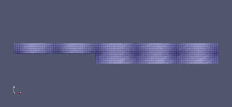 mesh with No Grading.
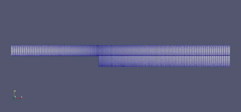 mesh with grading factor of 0.2.
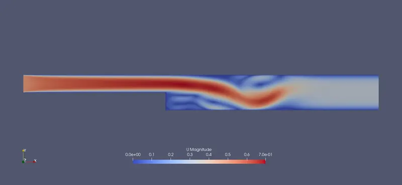
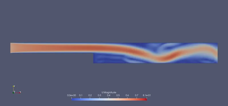
Velocity profile for no grading factor.
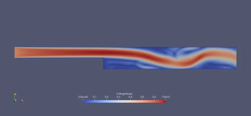
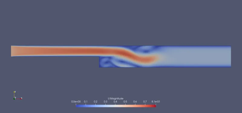
Velocity profile for Grading Factor of 0.2
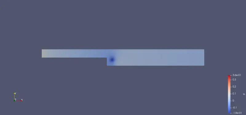
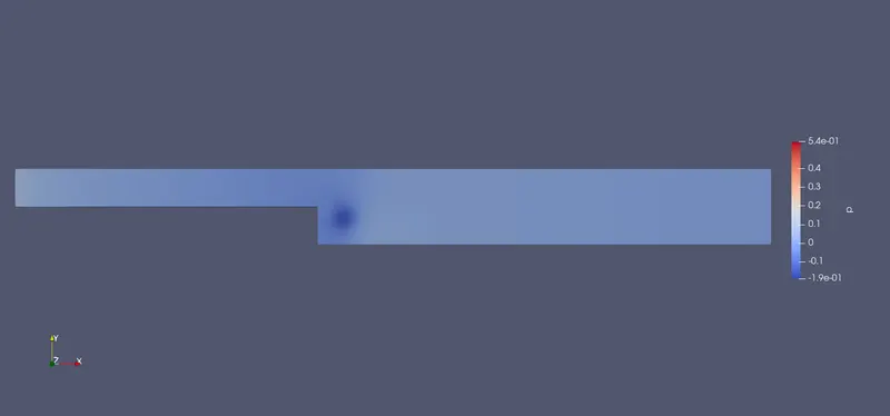
Pressure Profile with No Grading
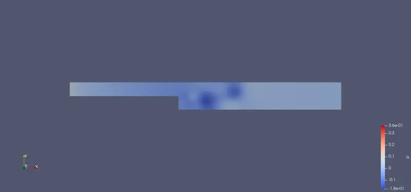
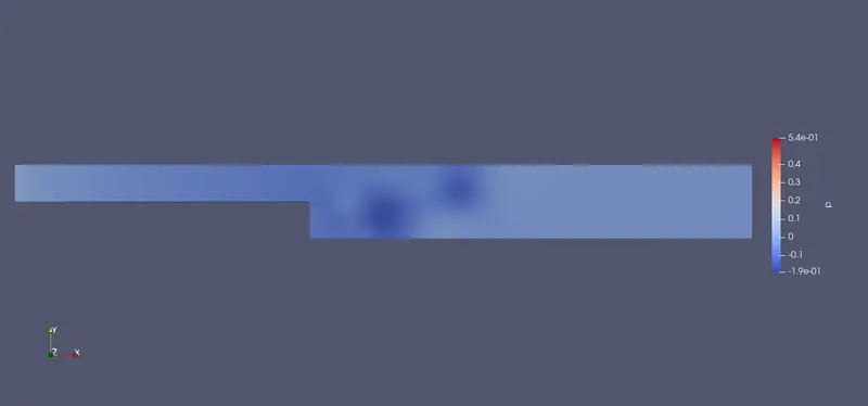
Pressure Profile with Grading Factor of 0.2
Line Probe at 0.085m from inlet with no grading
Line Probe at 0.085m from inlet with grading factor of 0.2
Conclusion:
- From the line probe for both the cases with no grading factor and 0.2 grading factor we can see that the graph is not as smooth as the graph for the no grading that is only because the point that are collected for little discontinous graph is from the section where the mesh is a little coarser.
- But with graded mesh we can capture the boundary layer as well as the recirculation zone after the step very clearly.
- The vortex from the step to the outlet is also captured very neatly as with the case no grade mesh only the vortex near the step is seen.
- Mesh Grading is a very efficient way of capturing the main details of the case without increasing the number of cells that in return increases the computational time.