Week 8 - Simulation of a backward facing step in OpenFOAM
Objective:
To perform a incompressible-laminar-viscous flow simulation on a backward facing step and demonstrate the following:
1) Steps in solving the given problem with the help of OpenFoam
2) Study of grading factor and its effect on the simulation considering two case studies (with the help of velocity profile at 0.085 m)
1. Problem definition:
Backward facing step:
The backward facing geometry is given in the problem and it is attached below:
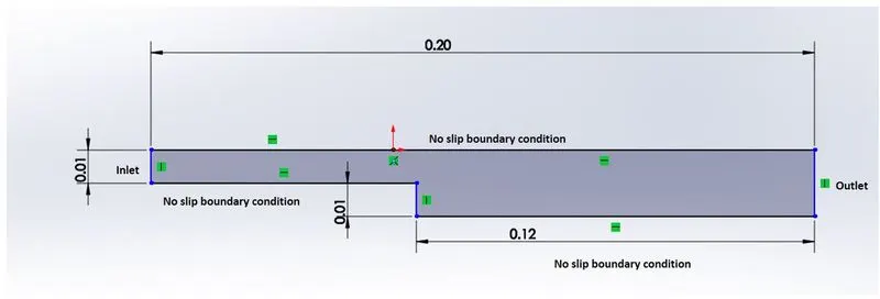
The flow is assumed to be an incompressible-laminar-viscous condition. The problem is solved in a two dimensional plane, considering the third dimension to have a null unit.
2D-Incompressible-Laminar-viscous flow solution:
The incompressible laminar viscous flow governing equation is given below:
`(delvecV)/(delt)+(vecV.Delta)vecV-nu.Delta^2.vecV=-1/rho.DeltaP+vecg`
OpenFoam uses icoFoam solver to solve the above equation numerically with the help of PISO algorithm. Not getting much into the detail about the solver methodology, the effect of meshing strategy is alone concentrated in this study.
2. Problem setup in OpenFoam:
Step 1: Use of tutorial problem as the reference file
A tutorial problem found in the path "$FOAM_TUTORIALS/incompressible/icoFoam/cavity" will be used and the necessary changes will be made to suit our given problem. The folder abovementioned is copied into the $FOAM_RUN directory.
Step 2: Mesh Generation
First step in the OpenFoam is to create the Geometry and generate meshing. This is done with the help of blockMeshDict file present in the sytem directory of the above copied folder.
The geometry given is divided into three sub-blocks as shown below(figure not in scale):
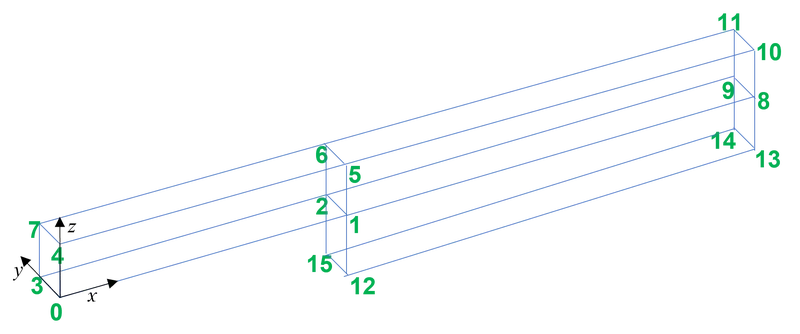
The sixteen vertices are marked as shown above. The nodal positions with respect to the origin position '0' is fed in the blockMechDict file. The boundary faces are divided into inlet, outlet, walls, and frontAndBack. All the information is fed into the blockMechDict file and it is altered as below:
/*--------------------------------*- C++ -*----------------------------------*\
  =========                 |
  \\      /  F ield         | OpenFOAM: The Open Source CFD Toolbox
   \\    /   O peration     | Website:  https://openfoam.org
    \\  /    A nd           | Version:  9
     \\/     M anipulation  |
\*---------------------------------------------------------------------------*/
FoamFile
{
    format      ascii;
    class       dictionary;
    object      blockMeshDict;
}
// * * * * * * * * * * * * * * * * * * * * * * * * * * * * * * * * * * * * * //

convertToMeters 0.01;

vertices
(
    (0 0 0)    //0
    (8 0 0)    //1
    (8 0.1 0)    //2
    (0 0.1 0)    //3
    (0 0 1)    //4
    (8 0 1)    //5
    (8 0.1 1)    //6
    (0 0.1 1)    //7
    (20 0 0)    //8
    (20 0.1 0)    //9
    (20 0 1)    //10
    (20 0.1 1)    //11
    (8 0 -1)    //12
    (20 0 -1)    //13
    (20 0.1 -1)    //14
    (8 0.1 -1)    //15
);

blocks
(
    hex (0 1 2 3 4 5 6 7) (80 1 10) simpleGrading (1 1 1) //block 1
    hex (1 8 9 2 5 10 11 6) (120 1 10) simpleGrading (1 1 1) //block 2
    hex (12 13 14 15 1 8 9 2) (120 1 10) simpleGrading (1 1 1) //block 3
);

edges
(
);

boundary
(
    inlet
    {
        type patch;
        faces
        (
            (0 4 7 3) //front
        );
    }
    outlet
    {
        type patch;
        faces
        (
            (8 9 11 10) //back
            (13 14 9 8) //back
        );
    }
    walls
    {
        type wall;
        faces
        (
            (0 3 2 1)  //bottom
            (12 15 14 13) //bottom
	    (4 5 6 7) //top
	    (5 10 11 6) //top
	    (15 12 1 2) //leftdown
        );
    }
    frontAndBack
    {
        type empty;
        faces
        (
            (0 1 5 4) //front
            (1 8 10 5) //front
            (12 13 8 1) //front
            (7 6 2 3) //back
            (6 11 9 2) //back
            (2 9 14 15) //back
        );
    }
);

mergePatchPairs
(
);

// ************************************************************************* //
We consider two cases for studying the effect of meshing as follows
Case 1: Simple grading
The grading factor is set to 1 and the generated mesh is attached here. Here we have used a simple grading i.e., the number of mesh elements divided equally along the mesh axis. The total number of mesh elements along X axis is 200, and about Z axis is 20.

The uniform size of the mesh elements here will be 0.2/200=0.001 m along X-axis and 0.02/20=0.001 m along Y-axis as well.
Case 2: Multi-grading:
Our case 2 is to simulate the flow with a grading factor of 0.2. The cells should be also finer near the walls (including the step wall). In order to do this we can alter the simple grading into multi-grading. This can be done by altering the blocks section as follows:
blocks
(
    hex (0 1 2 3 4 5 6 7) (80 1 10)
	simpleGrading
	(
	(   			// x-direction expansion ratio
            (0.2 0.3 5)    // 20% x-dir, 30% cells, expansion = 5
            (0.6 0.4 1)    // 60% x-dir, 40% cells, expansion = 1
            (0.2 0.3 0.2) // 20% x-dir, 30% cells, expansion = 0.2 (1/5)
        )
	1   			// y-direction expansion ratio
	(   			// z-direction expansion ratio
            (0.2 0.3 5)    // 20% z-dir, 30% cells, expansion = 5
            (0.6 0.4 1)    // 60% z-dir, 40% cells, expansion = 1
            (0.2 0.3 0.2) // 20% z-dir, 30% cells, expansion = 0.2 (1/5)
        )
	)	//block 1
    hex (1 8 9 2 5 10 11 6) (120 1 10)
	simpleGrading
	(
	(   			// x-direction expansion ratio
            (0.2 0.3 5)    // 20% x-dir, 30% cells, expansion = 5
            (0.6 0.4 1)    // 60% x-dir, 40% cells, expansion = 1
            (0.2 0.3 0.2) // 20% x-dir, 30% cells, expansion = 0.2 (1/5)
        )
	1   			// y-direction expansion ratio
	(   			// z-direction expansion ratio
            (0.2 0.3 5)    // 20% z-dir, 30% cells, expansion = 5
            (0.6 0.4 1)    // 60% z-dir, 40% cells, expansion = 1
            (0.2 0.3 0.2) // 20% z-dir, 30% cells, expansion = 0.2 (1/5)
        )
	)	//block 2
    hex (12 13 14 15 1 8 9 2) (120 1 10)
	simpleGrading
	(
	(   			// x-direction expansion ratio
            (0.2 0.3 5)    // 20% x-dir, 30% cells, expansion = 5
            (0.6 0.4 1)    // 60% x-dir, 40% cells, expansion = 1
            (0.2 0.3 0.2) // 20% x-dir, 30% cells, expansion = 0.2 (1/5)
        )
	1   			// y-direction expansion ratio
	(   			// z-direction expansion ratio
            (0.2 0.3 5)    // 20% z-dir, 30% cells, expansion = 5
            (0.6 0.4 1)    // 60% z-dir, 40% cells, expansion = 1
            (0.2 0.3 0.2) // 20% z-dir, 30% cells, expansion = 0.2 (1/5)
        )
	)	//block 3
);
In all the blocks we tried to transform the mesh in a way to arrange the cells finer near to the walls. For doing that we splitted the cells into three partitions. The first partition of 20 % length will cover 30 % cells with a grading factor of 5, the second partition will have only 40% cells in 60% length with a simple grading, and the third partition will have 30% cells in 20% length with a grading factor of 0.2. We have used this method to ensure a finer mesh nearer to the walls.
Here the cell size will be divided based on geometric progression with the ratio of last cell to the first cell in the ratio of the given grading factor.
So to calculate the minimum cell size, we can do the following steps. Let us consider z axis in block 1. The length of the block in z direction is 0.01 m and number of cells is 10. Now for the first partition we divide 20% length i.e., 0.002 m into 30 % cells i.e., 3 cells.
The cells are arranged in geometric progression i.e., `alpha, alphabeta,alphabeta^2,....alphabeta^(n-1)` for n elements. Here `beta` is the common ratio (Ratio of two successive terms).
We know that the ratio
`("Last cell size")/("first cell size")=(alphabeta^(n-1))/alpha="grading factor"(r)`
and
`beta=r^(1/(n-1))` ------(1)
`alpha+alphabeta+alphabeta^2+....+alphabeta^(n-1)="Length of the partition"`
Or
`alpha(beta^n-1)/(beta-1)="Length of the partition"`--------(2)
So in block 1, From (1)`beta` will be equal to 2.236068 and substituting this again into (2) we get `alpha`=0.0002428. So the minimum cell size here is 0.0002428.
Similarly let us consider in other direction and find the minimum cell size. The final outcomes are tabulated here:
| No. of cells | Length of the block | Length of the partition (20%) | No. of cells (30%) | Grading factor (r) | Common ratio (beta) | First cell size, (alpha) | |
| Block 1, z direction | 10 | 0.01 | 0.002 | 3 | 5 | 2.236068 | 0.000242834 |
| Block 1, x direction | 80 | 0.08 | 0.016 | 24 | 5 | 1.072482 | 0.000265842 |
| Block 2, x direction | 120 | 0.12 | 0.024 | 36 | 5 | 1.047058 | 0.000266666 |
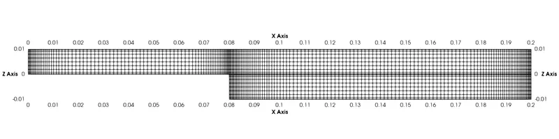
So the minimum cell size thus obtained due to grading factor will be 0.000242834 m which will be closer to the wall. In case 1, the uniform cell size was 0.001 m which is approximately four times larger than this case. However the maximum cell size in case 2, will be at the center, which will be equal to 0.0015 m for all the blocks as shown below. Also this maximum size is larger than the uniform cell size of the previous case.
| No. of cells | Length of the block | Length of the partition (60%) | No. of cells (40%) | Grading factor (r) | Cell size | |
| Block 1, z direction | 10 | 0.01 | 0.006 | 4 | 1 | 0.0015 |
| Block 1, x direction | 80 | 0.08 | 0.048 | 32 | 1 | 0.0015 |
| Block 2, x direction | 120 | 0.12 | 0.072 | 48 | 1 | 0.0015 |
The obtained mesh geometry is attached here:
Step 3: Setting Boundary and Initial conditions
We have to setup the initial and boundary conditions for pressure and velocity to solve the differential equation numerically. For both the cases of study we use the same conditions.
The kinematic pressure field is set as follows in the '0' folder.
/*--------------------------------*- C++ -*----------------------------------*\
  =========                 |
  \\      /  F ield         | OpenFOAM: The Open Source CFD Toolbox
   \\    /   O peration     | Website:  https://openfoam.org
    \\  /    A nd           | Version:  9
     \\/     M anipulation  |
\*---------------------------------------------------------------------------*/
FoamFile
{
    format      ascii;
    class       volScalarField;
    object      p;
}
// * * * * * * * * * * * * * * * * * * * * * * * * * * * * * * * * * * * * * //

dimensions      [0 2 -2 0 0 0 0];

internalField   uniform 0;

boundaryField
{
    inlet
    {
        type            zeroGradient;
    }

    outlet
    {
        type            fixedValue;
        value           uniform 0;
    }

    walls
    {
        type            zeroGradient;
    }

    frontAndBack
    {
        type            empty;
    }
}

// ************************************************************************* //
Here the internal nodes are set initially at zero kinematic pressure. The inlet and walls are assumed to have zero gradient. The frontAndBack patch is assumed to have type empty which means we do not require any solution in the respective direction i.e., the `z` direction. Our problem will be solved in the `x` and `y` direction only.
The velocity field is set as follows:
/*--------------------------------*- C++ -*----------------------------------*\
  =========                 |
  \\      /  F ield         | OpenFOAM: The Open Source CFD Toolbox
   \\    /   O peration     | Website:  https://openfoam.org
    \\  /    A nd           | Version:  9
     \\/     M anipulation  |
\*---------------------------------------------------------------------------*/
FoamFile
{
    format      ascii;
    class       volVectorField;
    object      U;
}
// * * * * * * * * * * * * * * * * * * * * * * * * * * * * * * * * * * * * * //

dimensions      [0 1 -1 0 0 0 0];

internalField   uniform (0 0 0);

boundaryField
{
    inlet
    {
        type            fixedValue;
        value           uniform (0.5 0 0);
    }

    outlet
    {
        type            zeroGradient;
    }
    walls
    {
        type            noSlip;
    }

    frontAndBack
    {
        type            empty;
    }
}

// ************************************************************************* //
The flow at the inlet patch is assumed to have a velocity of 0.5 m/s initially. This is assumed in a way to have a laminar flow at the inlet. We have `Re=(|U|D)/nu=(0.5*0.01)/10^-5=500`. The `"Reynolds number"` here is lesser than the critical reynolds number of 2000.
Step 4:Setting Physical properties
In the constant folder, we have the `"transportProperties"` file where we can set the value for kinematic viscosity. We set the value as `10^-5`. The code is attached here, which is the same for both the cases
/*--------------------------------*- C++ -*----------------------------------*\
  =========                 |
  \\      /  F ield         | OpenFOAM: The Open Source CFD Toolbox
   \\    /   O peration     | Website:  https://openfoam.org
    \\  /    A nd           | Version:  9
     \\/     M anipulation  |
\*---------------------------------------------------------------------------*/
FoamFile
{
    format      ascii;
    class       dictionary;
    location    "constant";
    object      transportProperties;
}
// * * * * * * * * * * * * * * * * * * * * * * * * * * * * * * * * * * * * * //

nu              [0 2 -1 0 0 0 0] 1e-05;


// ************************************************************************* //
Step 5: Setting the controlDict file to ensure Courant number is <1
The `"controlDict"` file specifies the time control for the problem. The time parameters are set specifically for both the cases of study so as to ensure the courant number(`"Co"`) is less than `1` for convergence.
For case 1: Simple grading
For this case the uniform mesh size is 0.001 m. The courant number for the minimum mesh size size should be lesser than or equal to one. Here `(deltax)_(min)=0.001`. We have `Co=(deltat|U|)/(deltax)_(min)`. For `Co` to be `<=1` , `deltat` should be `<=(Co*(deltax)_(min))/|U|` i.e., `deltat<=1*0.001/0.5=0.002`. In our case we took time step to be 0.002 itself. The output of `p` and `U` is written after every tenth iteration i.e., at interval of 0.02 second. This information is specified in the `"controlDict"` file located in the system folder. The code is attached below
/*--------------------------------*- C++ -*----------------------------------*\
  =========                 |
  \\      /  F ield         | OpenFOAM: The Open Source CFD Toolbox
   \\    /   O peration     | Website:  https://openfoam.org
    \\  /    A nd           | Version:  9
     \\/     M anipulation  |
\*---------------------------------------------------------------------------*/
FoamFile
{
    format      ascii;
    class       dictionary;
    location    "system";
    object      controlDict;
}
// * * * * * * * * * * * * * * * * * * * * * * * * * * * * * * * * * * * * * //

application     icoFoam;

startFrom       startTime;

startTime       0;

stopAt          endTime;

endTime         6;

deltaT          0.002;

writeControl    timeStep;

writeInterval   10;

purgeWrite      0;

writeFormat     ascii;

writePrecision  6;

writeCompression off;

timeFormat      general;

timePrecision   6;

runTimeModifiable true;


// ************************************************************************* //
For case 2: Multi-grading
For this case the uniform mesh size is 0.000242834 m. The courant number for the minimum mesh size size should be lesser than or equal to one. For that `deltat<=1*0.000242834/0.5=0.000485668`. In our case we took time step to be 0.0004 to ensure the `Co<1`. The output of `p` and `U` is written after every `50^(th)` iteration i.e., at time interval of 0.02 second. The `"controlDict"` file is attached below
/*--------------------------------*- C++ -*----------------------------------*\
  =========                 |
  \\      /  F ield         | OpenFOAM: The Open Source CFD Toolbox
   \\    /   O peration     | Website:  https://openfoam.org
    \\  /    A nd           | Version:  9
     \\/     M anipulation  |
\*---------------------------------------------------------------------------*/
FoamFile
{
    format      ascii;
    class       dictionary;
    location    "system";
    object      controlDict;
}
// * * * * * * * * * * * * * * * * * * * * * * * * * * * * * * * * * * * * * //

application     icoFoam;

startFrom       startTime;

startTime       0;

stopAt          endTime;

endTime         6;

deltaT          0.0004;

writeControl    timeStep;

writeInterval   50;

purgeWrite      0;

writeFormat     ascii;

writePrecision  6;

writeCompression off;

timeFormat      general;

timePrecision   6;

runTimeModifiable true;


// ************************************************************************* //
3. Obtaining the solution:
The `"icoFoam"` solver is executed with the help of running `"icoFoam"` comment at the respective (`"cavity"`) directory. The iteration will stop after time = 6 seconds (as we programmed). The output files with values of `p` and `U` for time interval of 0.02 seconds is saved in the respective directory. We can view the solution through the `"Paraview"` post processing tool. The results are discussed below.
4. Results and discussions:
| Case 1: Simple Grading | Case 2: Multi grading with Grading factor =0.2 |
|
Pressure plot at time t = 6 seconds
|
Pressure plot at time t = 6 seconds
|
|
Velocity magnitude plot at time t = 6 seconds
|
Velocity magnitude plot at time t = 6 seconds
|
|
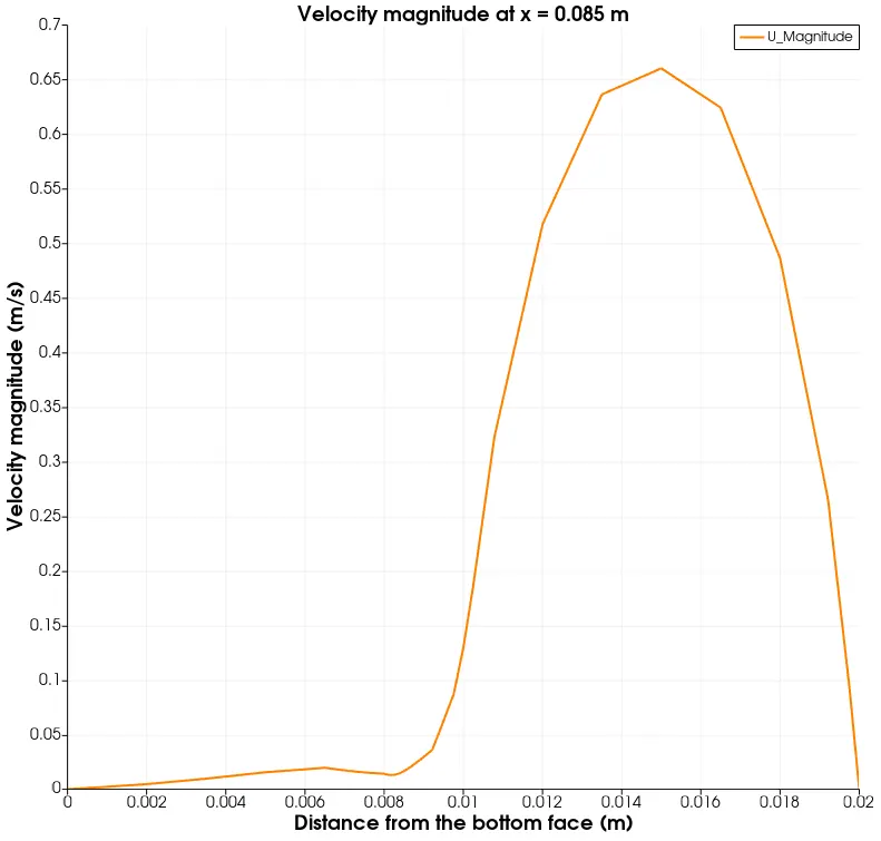
Line plot for Velocity magnitude
|
Line plot for Velocity magnitude
|
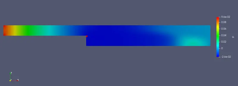
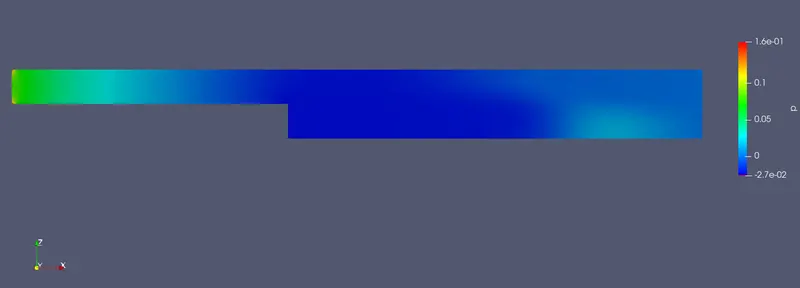
From the pressure contour plot, we can see that there is no high pressure region near to the step if the grading factor is taken into account. This high pressure region is present in the case with simple grading.
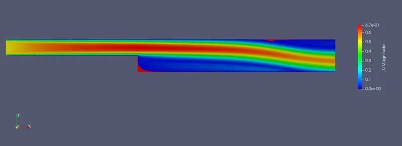
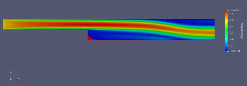
From the velocity contour plot we can see two differences; Firstly for case 2, the contour lines are curved at the downstream due to the influence of no slip condition at the walls. Secondly, the variation of velocity from the walls to the centre is clearly noticed only when a fine mesh is used near to the walls i.e., for case 2.
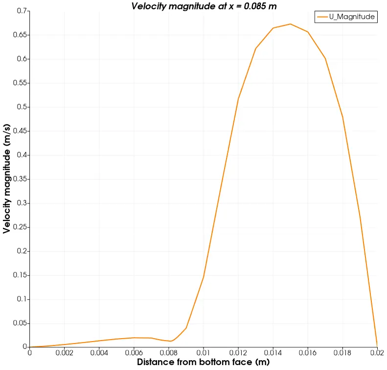
From the line plot we can notice the maximum velocity magnitude is reduced if we consider the grading factor of 0.2.
Conclusion:
There is an improvement in the overall results if the grading factor is used in such a way that the mesh is finer near the walls. The boundary layer effects are captured significantly if we use the same.