Week 8 - Simulation of a backward facing step in OpenFOAM
Aim:
To simulate the turbulent flow of air in a backward step for different base grid size and give the suitable conclusion
Theory:
The separate flow generated as fluid passes over a backward-facing step is of interest for a variety of reasons. First separated flows produced by an abrupt change in the geometry are of great importance in many engineering applications also the backward-facing step is an extreme example of separated floes that occur in aerodynamic devices such as high lift, airfoils at a large angle of attack. In these flows, separation may be created by a strong adverse pressure gradient rather than a geometric perturbation.
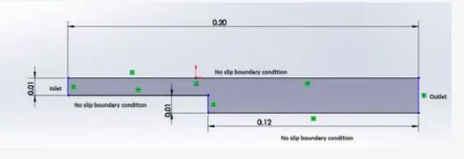
Objective: this project is to set up create a geometry buy editing blockMeshDict file to simulate a flow through backward-facing step for different grading factors.
To set up the geometry the figure was divided into 5 parts or blocks, a total number of cells along the x-direction is 120 which is divided as 80 no of cells for blocks no 0,1,2,3,4 for y-direction total number of cells is 10 which is divided as 5 cells each block in the y-direction.
Explanation of my simulation:
OpenFOAM code:
in OpenFOAM go to the tutorial file and incompressible file and then icoFoam, copy the cavity file to our required dictionary.
Block mesh dict: in the following code we have created the required geometry for grading factor 1 and 0.2 and we also assigned the boundary condition. This we did in the blockMeshDict file of the system in the cavity tutorial
/*--------------------------------*- C++ -*----------------------------------*\
  =========                 |
  \\      /  F ield         | OpenFOAM: The Open Source CFD Toolbox
   \\    /   O peration     | Website:  https://openfoam.org
    \\  /    A nd           | Version:  8
     \\/     M anipulation  |
\*---------------------------------------------------------------------------*/
FoamFile
{
    version     2.0;
    format      ascii;
    class       dictionary;
    object      blockMeshDict;
}
// * * * * * * * * * * * * * * * * * * * * * * * * * * * * * * * * * * * * * //

convertToMeters 1;

vertices
(
    (0 0 0)   		  //0
    (0.08 0 0)  	  //1
    (0.08 0.005 0)  	  //2
    (0 0.005 0)   	  //3
    (0.08 0.01 0)        //4
    (0 0.01 0)    	  //5
    (0.2 0.01 0)    	  //6
    (0.2 0.005 0)        //7
    (0.2 0 0)  	  //8
    (0.2 -0.005 0)        //9
    (0.08 -0.005 0)       //10
    (0 0 0.01)          //11
    (0.08 0 0.01)       //12
    (0.08 0.005 0.01)   //13
    (0 0.005 0.01)      //14
    (0.08 0.01 0.01)    //15
    (0 0.01 0.01)       //16
    (0.2 0.01 0.01)     //17
    (0.2 0.005 0.01)    //18
    (0.2 0 0.01)        //19
    (0.2 -0.005 0.01)    //20
    (0.08 -0.005 0.01)   //21
);

blocks
(
    hex (0 1 2 3 11 12 13 14) (120 5 1) simpleGrading (1 1 1)
    hex (3 2 4 5 14 13 15 16) (120 5 1) simpleGrading (1 1 1)
    hex (2 7 6 4 13 18 17 15) (80 5 1) simpleGrading (1 1 1)
    hex (1 8 7 2 12 19 18 13) (80 5 1) simpleGrading (1 1 1)
    hex (10 9 8 1 21 20 19 12) (80 5 1) simpleGrading (1 1 1)
);

edges
(
);

boundary
(
    movingWall
    {
        type patch;
        faces
        (
            (0 3 11 14)
            (3 14 16 5)
        );
    }
    fixedWalls
    {
        type patch;
        faces
        (
            (7 6 17 18)
            (8 7 18 19)
            (9 8 19 20)
        );
    }
    frontAndBack
    {
        type empty;
        faces
        (
            (11 14 12 13)
            (14 16 13 15)
            (13 15 18 17)
            (12 13 19 18)
            (21 12 20 19)
            (0 3 2 1)
            (3 5 4 2)
            (2 4 6 7)
            (1 2 7 8)
            (10 1 8 9)
        );
    }
    Noslipwalls
    {
    	type wall;
    	faces
    	(
    	     (5 16 15 4)
    	     (4 15 17 6)
    	     (10 1 21 12)
    	     (0 1 12 11)
    	     (10 9 20 21)
    	  );
     }
);

mergePatchPairs
(
);

// ************************************************************************* //
controlDict file:
in the following code we have assigned the start time, end time as well as time steps. This we did it in the controlDict file of system folder in cavity tutorial.
/*--------------------------------*- C++ -*----------------------------------*\
  =========                 |
  \\      /  F ield         | OpenFOAM: The Open Source CFD Toolbox
   \\    /   O peration     | Website:  https://openfoam.org
    \\  /    A nd           | Version:  8
     \\/     M anipulation  |
\*---------------------------------------------------------------------------*/
FoamFile
{
    version     2.0;
    format      ascii;
    class       dictionary;
    location    "system";
    object      controlDict;
}
// * * * * * * * * * * * * * * * * * * * * * * * * * * * * * * * * * * * * * //

application     icoFoam;

startFrom       startTime;

startTime       0;

stopAt          endTime;

endTime         0.5;

deltaT          0.0005;

writeControl    timeStep;

writeInterval   20;

purgeWrite      0;

writeFormat     ascii;

writePrecision  6;

writeCompression off;

timeFormat      general;

timePrecision   6;

runTimeModifiable true;


// ************************************************************************* //
Velocity File:
In this folloeing code we have assign the value for velocity for boundary condition and also for different patch. This we did in the U file of constant folder in cavity tutorial
/*--------------------------------*- C++ -*----------------------------------*\
  =========                 |
  \\      /  F ield         | OpenFOAM: The Open Source CFD Toolbox
   \\    /   O peration     | Website:  https://openfoam.org
    \\  /    A nd           | Version:  8
     \\/     M anipulation  |
\*---------------------------------------------------------------------------*/
FoamFile
{
    version     2.0;
    format      ascii;
    class       volVectorField;
    object      U;
}
// * * * * * * * * * * * * * * * * * * * * * * * * * * * * * * * * * * * * * //

dimensions      [0 1 -1 0 0 0 0];

internalField   uniform (0 0 0);

boundaryField
{
    movingWall
    {
        type            fixedValue;
        value           uniform (3 0 0);
    }

    fixedWalls
    {
        type            zeroGradient;
    }

    frontAndBack
    {
        type            empty;
    }

    Noslipwalls
    {
        type            noSlip;
    }
}

// ************************************************************************* //
Pressure file:
In the following code we have assign the value for preesure for boundary condition and also for different patch. This we did in P pressure file of constant folder in cavity.
/*--------------------------------*- C++ -*----------------------------------*\
  =========                 |
  \\      /  F ield         | OpenFOAM: The Open Source CFD Toolbox
   \\    /   O peration     | Website:  https://openfoam.org
    \\  /    A nd           | Version:  8
     \\/     M anipulation  |
\*---------------------------------------------------------------------------*/
FoamFile
{
    version     2.0;
    format      ascii;
    class       volScalarField;
    object      p;
}
// * * * * * * * * * * * * * * * * * * * * * * * * * * * * * * * * * * * * * //

dimensions      [0 2 -2 0 0 0 0];

internalField   uniform 0;

boundaryField
{
    movingWall
    {
        type            zeroGradient;
    }

    fixedWalls
    {
        type		fixedValue;
    	value		uniform 0;
    }

    frontAndBack
    {
        type            empty;
    }

    Noslipwalls
    {
        type            zeroGradient;
    }
}

// ************************************************************************* //
Results:
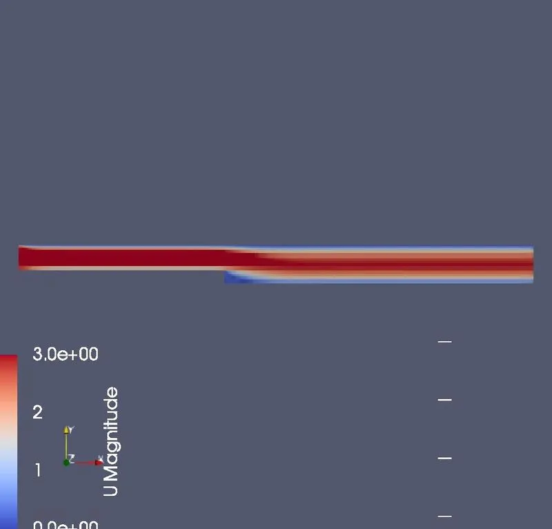
Following image shows the mesh with grid, and velocity mesh
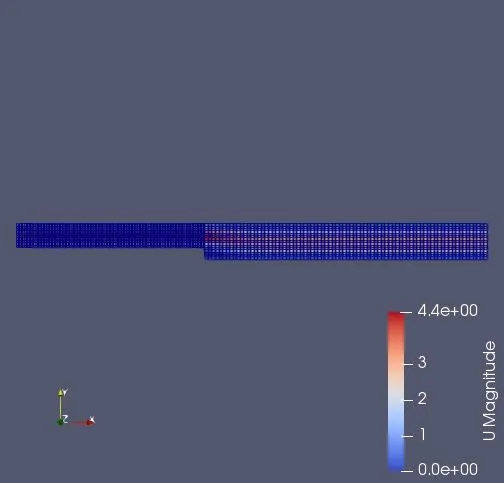
For grading factor 1:
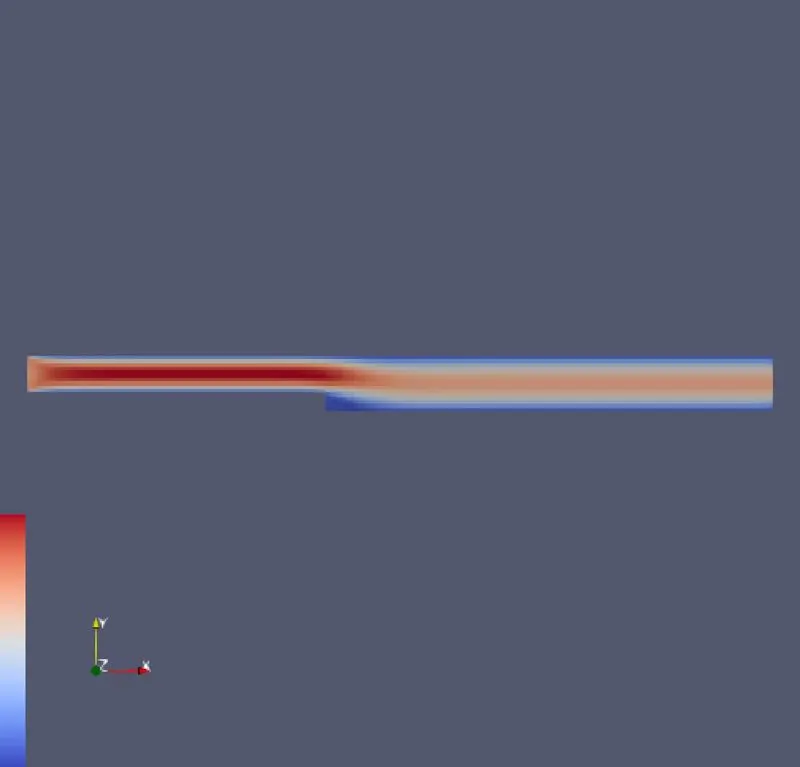
Velocity profile:
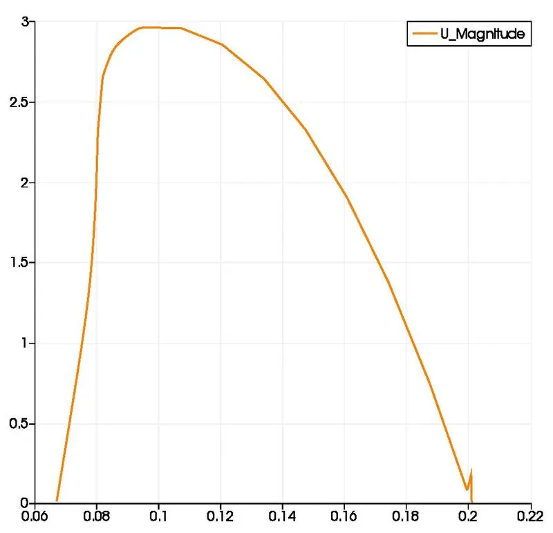
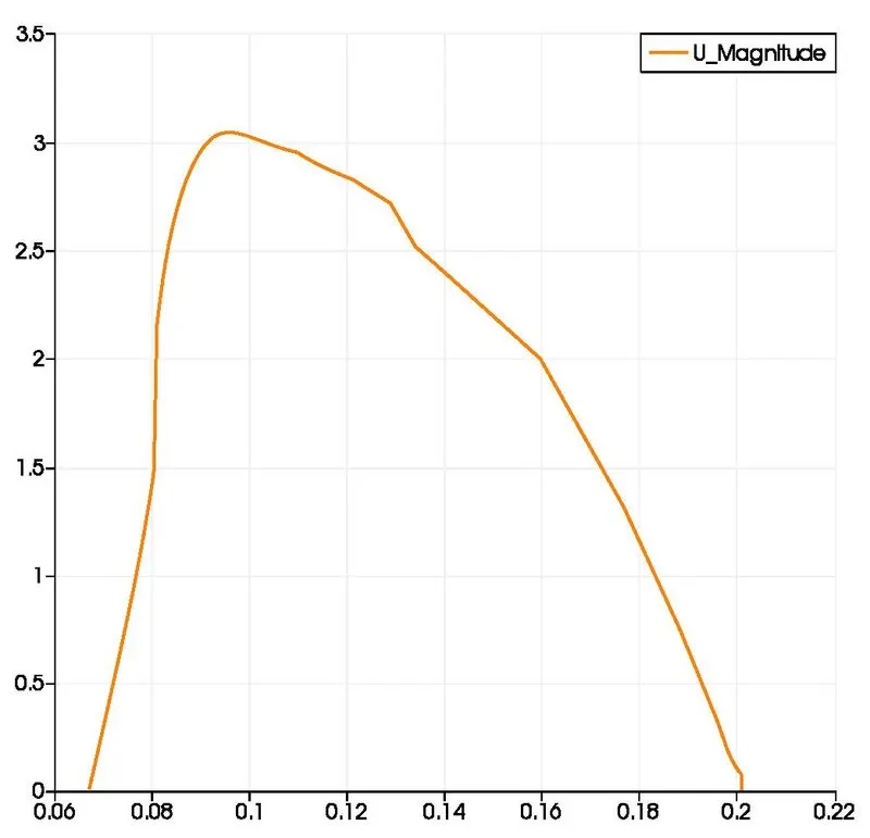
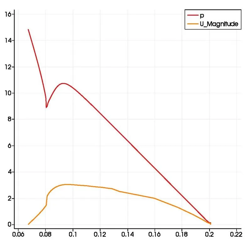
Line Plot velocity:
Mesh code for grding factor=0.5
blocks
(
    hex (0 1 2 3 11 12 13 14) (120 5 1) simpleGrading (0.2 0.2 1)
    hex (3 2 4 5 14 13 15 16) (120 5 1) simpleGrading (0.2 0.2 1)
    hex (2 7 6 4 13 18 17 15) (80 5 1) simpleGrading (5.0 0.2 1)
    hex (1 8 7 2 12 19 18 13) (80 5 1) simpleGrading (5.0 0.2 1)
    hex (10 9 8 1 21 20 19 12) (80 5 1) simpleGrading (5.0 0.2 1)
);
Same steps needs to follow but need to change grid factor as 0.5 in blockMeshDict file in blocks line
Velocity Profile:
Grading factor 1 Grading factor 0.2
https://drive.google.com/file/d/1Vzn668SDxAfBVE2RcFC-Mj_PlNcqLbX4/view?usp=sharing
Conclusion:
Line plot:
All above line plot is been obtained at x=0.085 and y=0.01, we different plot for different grading factor at same loction.
Velocity contour:
All above velocity contour is obtained for different grading factor at 1 and 0.5
And also after observing the above comparision we can conclude that grading factor affects the results. Finner grading factor at the wall create more clear simulation.