Week 8 - Simulation of a backward facing step in OpenFOAM
The main aim of the project is to simulate an incompressible laminar viscous flow through the backward facing step geometry.
The physics of the flow can be captured by using one of the tutorials from the OpenFoam directly.To simulate the flow over an backward step tutorial cavity is choosen which is presnt in the path shown below:
openfoam9/tutorials/incompressible/icoFoam/cavity.
The tutorial mentioned above has to modified in suh a way that our problem can be simulated.
The geometry ,boundary conditions and meshing used for the above tutorial has to be changed so that it represents our problem domain.The solver methodology , physics ,discretization techniques or the governing equations are not changed .
Steps involved in simulation: The steps involved in the simulation are showed and explained below in detail.
- First step is to copy the tutorial files into the openfoam run directory and rename it according to our preference.
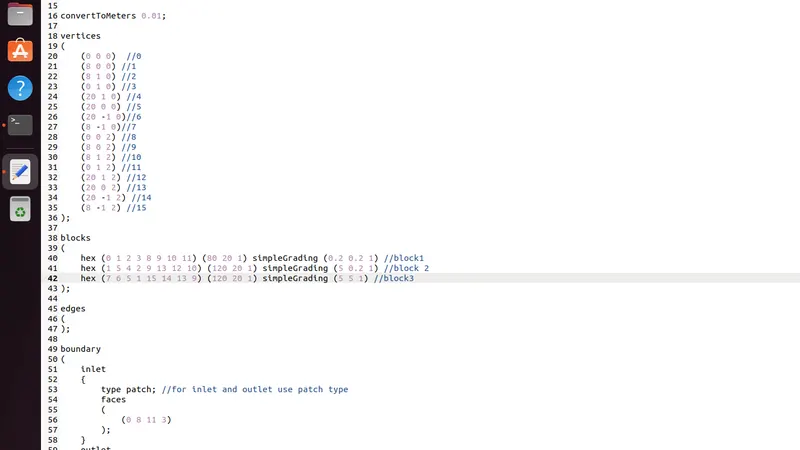
- The next main and important step is to modify the blockmestdict file which is available in system folder .
The blockmeshdict file has various parts each part of it has its own significance and is explained below.
- The first part involves defining the vertices of the geoemtry.Before stepping into this part we need to divide the geometry conviently into simler blocks so that it will be easy to define the mesh and bounday conditions.
- The geomerty in our case is divided into 3 blocks as shown below with respective numbering:
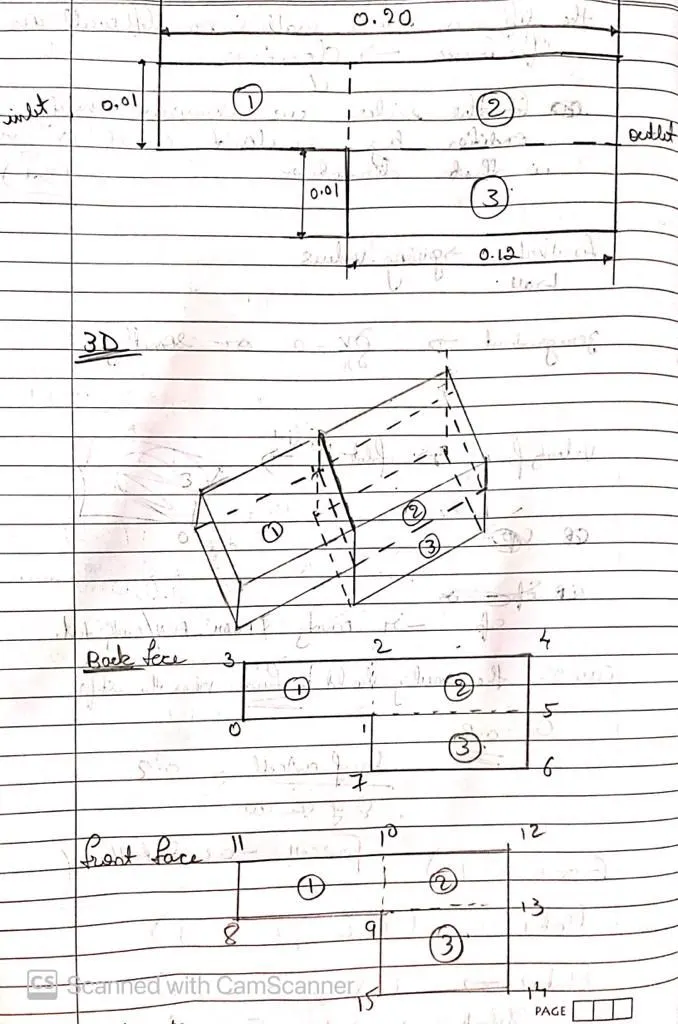
- By using the above image the blockmeshdict file is edited as follows:
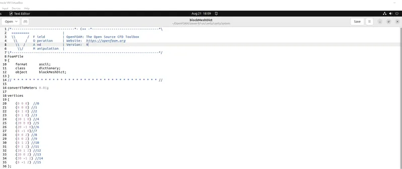
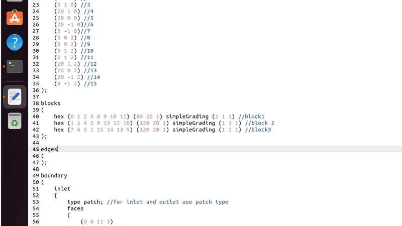
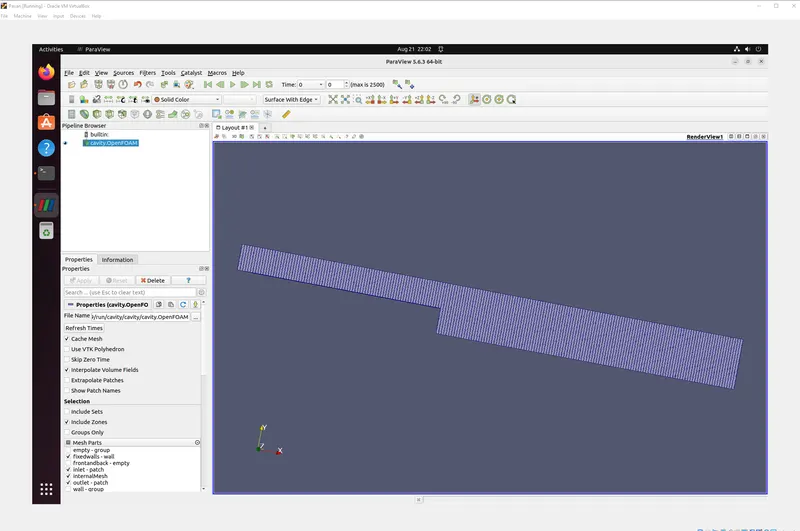
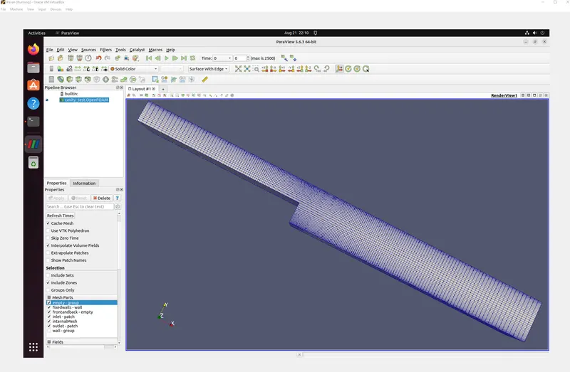
- The next step is meshing the geometry : In this part we have 2 cases
case 1: meshing is done with grading factor 1
case 2: meshing is done with grading factor 0.2.
The imporatance of grading factor is explained later in this document.
For both the case the number elements in x and y directions are 200 and 20 respectively.
case 1:
Mesh image case1:
case 2:
Mesh image case 2:
- In the meshing part the order of defining the vertices plays an imporant role .
- The next step is to define the boundary conditions .When defining the boundary conditions the order in which vertices need to be taken matters and it follows right hand thumb rule .
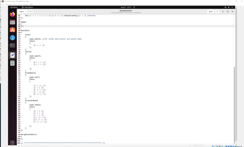
- By doing all mentioned above steps the blockmeshdict file is sucessfully edited to incorparate the necessary changes .
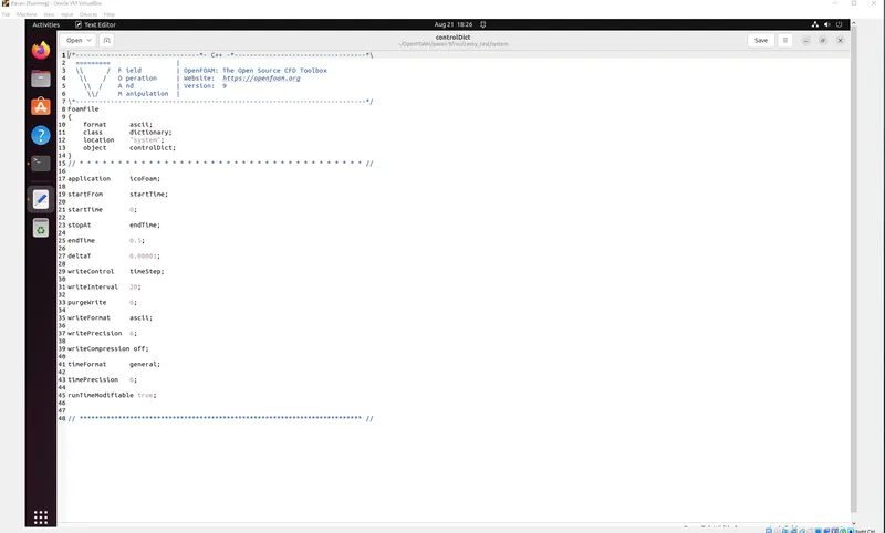
3. The next step is to edit the controldict file which is present in the system folder.
- In this file onlt the start, end , deltaT values are changed.
4. The final step is to provide the intial condtions for pressure and velocity .This cann be done by editing the files present in the folde '0'.
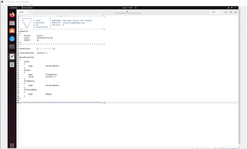
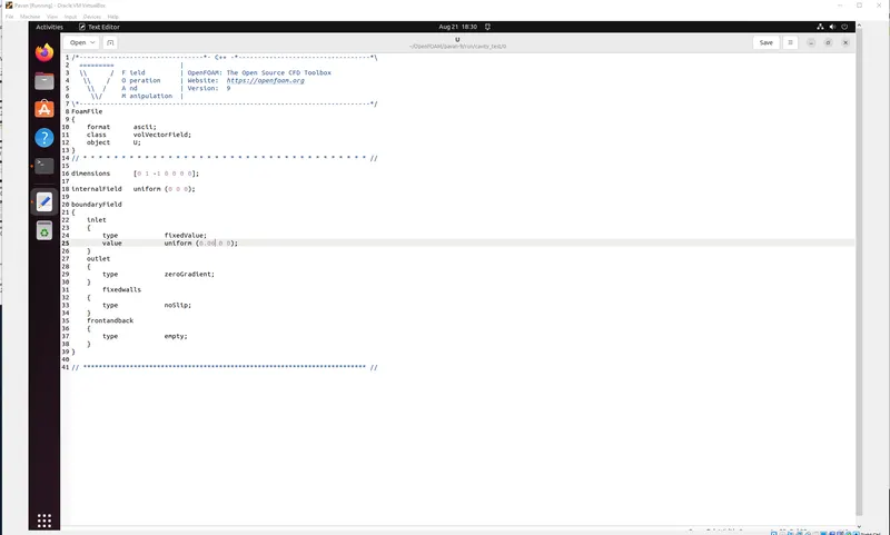
After all these steps the simulation can be run.
Before running the simulation mesh has to be checked or verified for any errors .This can be done by using checkmesh command.
The simualtion is carried out and the respective results can visulized by using postprocessing software parafoam.
Results and discussions:
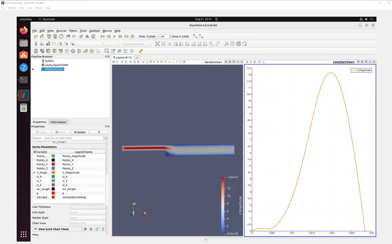
The velocity is measured at 0.085m from the inlet for both the cases.The results are shown below:
case 1: with grading factor 1
Case 2: With grading factor 0.2
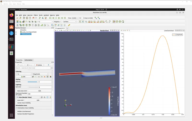
From the two diagrams there is no difference between the variation of velocity for both the cases .So this result helps us to think what is need for grading factor then?? This is explained below.
Need for grading factor: Before we get on to this what is grading factor??
Grading factor= size of last cell/ size of first cell
Grading factor enables or gives us the flexiblity to use same number of mesh elemnts to create coarse mesh and finer mesh at particular or at required location.
Lets consider the above two cases :In both the cases the total number of mesh elements are same but in the second case due to use of grading factor we were able to mesh finer at the critical location (step ) without using extra number of elements .
So in simple words grading factor gives us flexibility in meshiing .