Week 8 - Simulation of a backward facing step in OpenFOAM
===============================================================================
OpenFOAM Structure:
Every OpenFOAM case has atleast these 3 files; 0 , constant, system.
0 folder: This folder contains all the initial condition values of the flow field. One can apply boundary conditions with respect to varying problem statement.
Constant: This folder usually contains the transport properties, turbulence properties etc.
System: This folder contains the infomation regarding the mesh generation, geometry creation solution run time, discritization techinque, solver information etc.
NOTE: The information/folders inside theses three folders may vary depending problem statement.
===============================================================================
In this particular scenario we have simulated backward step (2D) using icoFoam solver, which simulates incompressible laminar flows and has a transient behaviour.
We will be discussing the involvement of each of these folders in detail.
STEP 1: Copy cavity tutorial folder from the icoFoam folder to your run folder.
STEP 2: Make changes according to your given problem statement.
CREATION OF GEOMETRY:
- Open system folder.
- Open blockMeshDict file via notepad (if using windows for subsystem linux). For linux users, they can work out the necessary changes using the gedit command.
Inside blockMeshDict,
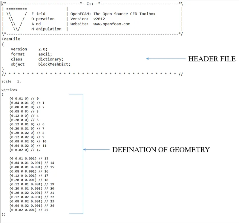
Geometry,
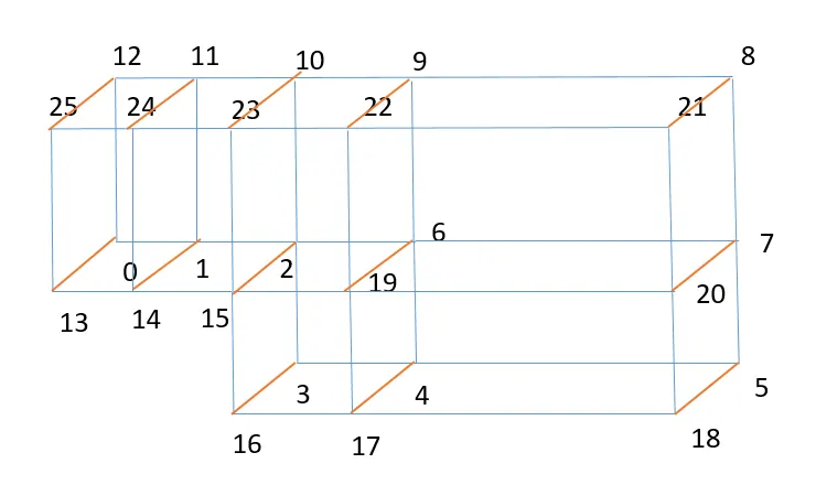
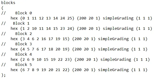
The blocks section defines the meshing throught the domain. Here the entire domain is divided into smaller domains for mesh refinement wherever necessary.
- The blocks section defines the meshing throught the domain.
- Here the entire domain is divided into smaller domains for mesh refinement wherever necessary.
- In the hex() inside the bracket the numbering should be in such a way that the back face points are written first and then the point of front face are written.
- After the hex (), number of mesh elements in x, y, z direction are specified (200 in x, 200 in y, 1 in z).
- Simple grading stretches the mesh in a particular direction. It is basically, the ration of last elemnt to the first element.
Boundary,
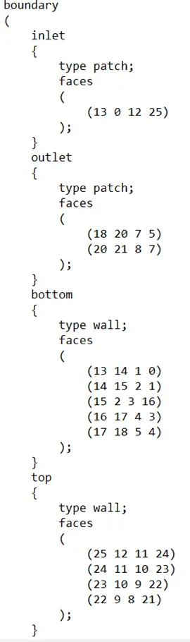
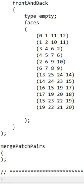
The boundaries are defined in anti-clockwise direction.
This problem contains,
- Inlet: The flow will start from here.
- Outlet: The flow leaves the domain from here.
- Bottom: They are defined as wall in order to capture the flow charateristics near the surface of the wall. (They act as wall)
- Top: They are defined as wall in order to capture the flow charateristics near the surface of the wall. (They act as wall)
- FrontandBack: They are given empty condition because we are solving a 2D problem. So assigning empty condition makes sure that we solve the equation in x and y direction and not in z direction.
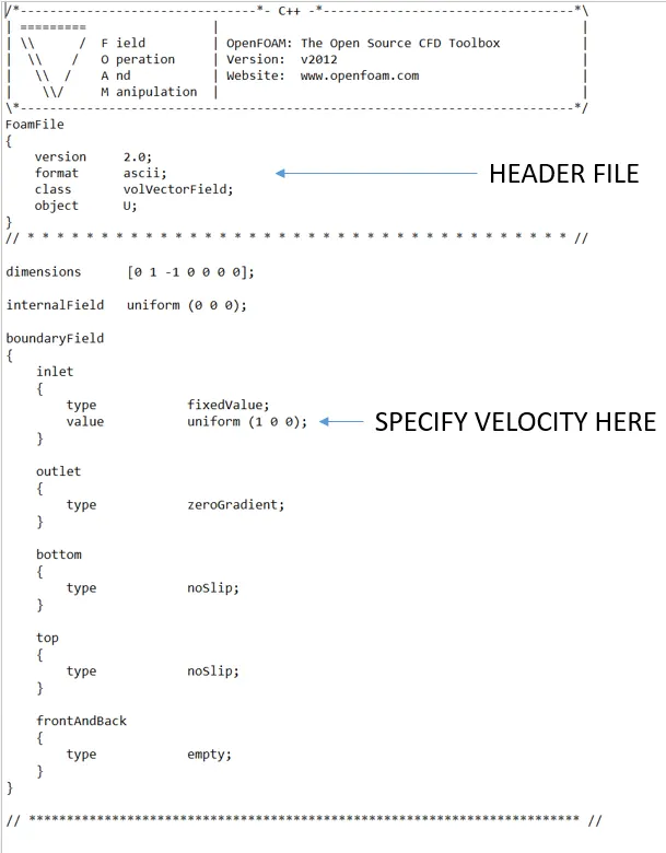
Specifing the velocity,
Navigate to 0 folder and open U.
Velocity near (very close) top wall and bottom wall is considered as 0. That is by defining noSlip boundary condition.
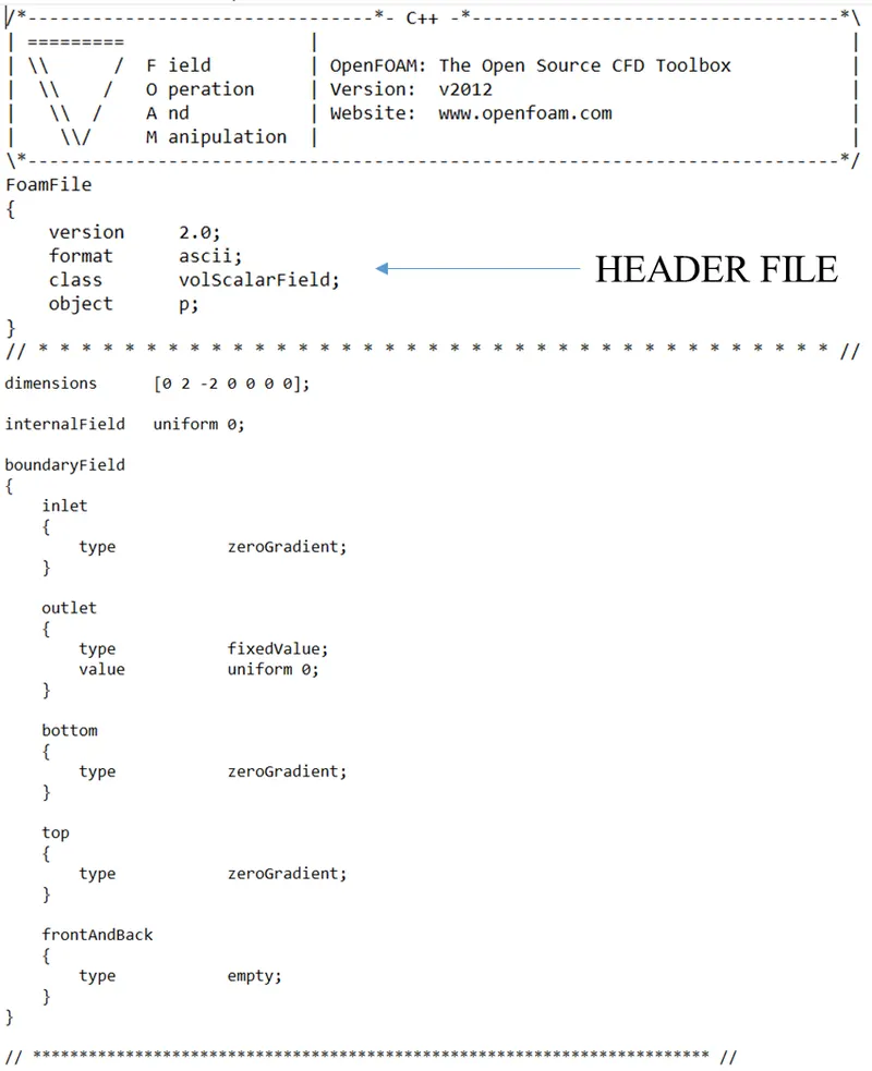
Similarly one can make changes in pressure file
NOTE: Here the pressure is kinematic pressure; pressure divided by density.
Solution control,
Navigate to system, and then open controlDict.
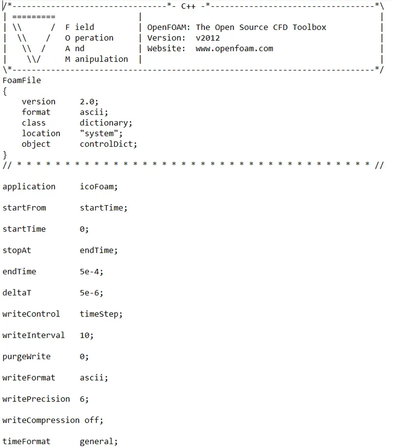
Here we mainly deal with the time values. ie endTime and deltaT.
One must specifiy the values of endTime and deltaT keeping mind the courant number value condition. Otherwise the solution will blow up.
RESULTS OF CHANGING THE simpleGrading value:
- Not much changes were seen in the value of velocity.
- One can say grid independence was attained.
The pictorial data is provided seperately.
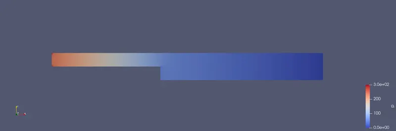
Pressure Contour:
Velocity Contour:
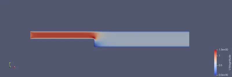
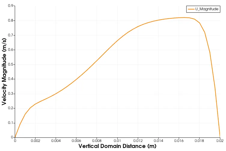
Velocity Plot at x=0.085m