Week 8 - Simulation of a backward facing step in OpenFOAM
Simulation of a backward-facing in Open FOAM
Aim:
- Simulate an incompressible—laminar-viscous flow through the Backward facing step geometry.
- Perform transient simulation; choose solver based on the Described physics of the flow in problem statement.
- Explain simulation process and way of setting up the problem Statement in open Foam and also, explain every changes that Have done inside the reference case files obtained from Open FOAM tutorials.
- Next, preform two case study, firstly, form simulation of the flow Without using any grading factor (i.e., CF = 1). Secondly, simulate The flow with grading factor of 0.2. The cells should be finer near The walls (including the step wall).
Objective:
- Open Foam tutorials and find the solver to solve incompressible-laminar-viscous flow problem.
- Next step is to copy required file in solver and paste it in Open FOAM run folder so that the official file of Open Foam remain untouched.
- Find out block mesh script file to create domain space and provide mesh specification.
- Find contradict’ file to edit start and end time for simulation.
- In initial folder O’ edit initial parameter for velocity and pressure according to faces of the given domain.
- Use block Mesh command to generate mesh and check Mesh to verify it.
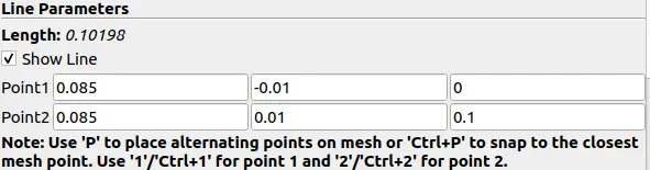
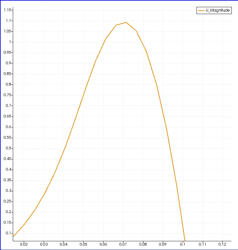
- Open simulation file in pa ra View and plot the velocity profile at point 0.085m from inlet
- Repeat above procedure for grading factor 0.2 to check the differences in results.
- Write a detailed report explaining all the command and codes used in project.
Problem Statement:
Simulate on Incompressible- laminar-viscous flow through the backward facing step geometry. Perform 2 case studies as described below and compare the results.
Case 1 - Simulate the flow without using any grading factor (i.e. OF = 1)
Case 2 - Simulate the flow with grading factor of 0.2. The cells should be liner near the walls (inciudig the step wall).
Mesh specification:
- Number of cells along the x direction (longer dimension) = 200
- Number of cells along the longer y direction = 20;
Boudary Condition specification:-
In order to start the simulation process, First start terminal in Linux Operating system using ctrl+alt+T buttons on key.We are using different type of command to perform the task. Each command is explain in following points.
-
Tutorial Directory:- we are going to solve our problem using tutorials present in openFOAM, therefore, just type 'tut’ to open OpenFOAM tutorial directory. And type 'ls’ to identify what kind of tutorials.
- Incompressible folders:-We have to solve incompressible flow simulation for this problem so select incompressible directory by typing cd incompressible’ and then again type Is to explore folders in incompressible folders.
- ‘icoFoam’:- For this particular solver we need solver for laminar- viscous flow, so here we choose ‘icoFoam’.icoFoam is the solver in open Foam which is use as transient solver for incompressible, laminar flow of Newtonian fluid (Newtonian fluid is a fluid in which the viscous stress arising from its flow, at every point, are linearly correlated to the local strain rate - the rate of change of its deformation over time. Newtonian fluids are the simplest mathematical models of fluids that account for viscosity.) Therefore, we will select icoFoam folder by typing ‘cd icoFoam’ and by typing ‘Is’ we explore this folder in terminal.
- Cavity :- In cavity, we are, again, going to see cavity folder, where we have to define our fluid domain and generate block mesh. But we are not going to make any changes here in tutorial section. First of all, Open Foam does no let anyone make any changes in their official tutorial and secondly, any changes with their official tutorials my corrupt open Foam. An in a bid to correct it, we may need to reinstall open foam all over again. So, we are going to copy this cavity folder using ‘cp -r cavity’ command and paste it in open Foam run folder by typing cp -r cavity $ FOAM _RUN/cavity test’. And then open run folder by typing ‘cd $FOAM_RUN’. Where we can see cavity test file.
- Now, we can make any changes to the cavity_test file, which will never affect the openFoam official files. Open cavity_test folder. Here, we can provide specification for our block mesh in system folder.
- BlockMeshDict :- There are 4 script file system folder and by opening blockMeshDict we can create domain and provide required specification for block mesh. So, open this file by typing gedit blockMeshDict’. Now we make follwing changes in blockmeshdict file
After,editing of blockmeshDic file save it and close it/*--------------------------------*- C++ -*----------------------------------*\ ========= | \\ / F ield | OpenFOAM: The Open Source CFD Toolbox \\ / O peration | Website: https://openfoam.org \\ / A nd | Version: 9 \\/ M anipulation | \*---------------------------------------------------------------------------*/ FoamFile { format ascii; class dictionary; object blockMeshDict; } // * * * * * * * * * * * * * * * * * * * * * * * * * * * * * * * * * * * * * // convertToMeters 1; vertices ( (0 0 0) //0 (0.08 0 0) //1 (0.08 0.005 0) //2 (0 0.005 0) //3 (0.08 0.01 0) //4 (0 0.01 0) //5 (0.20 0.01 0) //6 (0.20 0.005 0) //7 (0.20 0 0) //8 (0.20 -0.01 0) //9 (0.08 -0.01 0) //10 (0 0 0.1) //11 (0.08 0 0.1) //12 (0.08 0.005 0.1) //13 (0 0.005 0.1) //14 (0.08 0.01 0.1) //15 (0 0.01 0.1) //16 (0.20 0.01 0.1) //17 (0.20 0.005 0.1) //18 (0.20 0 0.1) //19 (0.20 -0.01 0.1) //20 (0.08 -0.01 0.1) //21 ); blocks ( hex (0 1 2 3 11 12 13 14) (80 5 1) simpleGrading (1 1 1) //block1 hex (3 2 4 5 14 13 15 16) (80 5 1) simpleGrading (1 1 1) //block2 hex (2 7 6 4 13 18 17 15) (120 5 1) simpleGrading (1 1 1) //block3 hex (1 8 7 2 12 19 18 13) (120 5 1) simpleGrading (1 1 1) //block4 hex (10 9 8 1 21 20 19 12)(120 10 1) simpleGrading (1 1 1) //block5 ); edges ( ); boundary ( Inlet { type patch; faces ( (0 11 14 3) (3 14 16 5) ); } outlet { type patch; faces ( (9 8 19 20) (8 7 18 19) (7 6 17 18) ); } Fixedwalls { type walls; faces ( (6 4 15 17) (4 5 16 15) (10 21 12 1) (12 11 0 1) (20 21 10 9) ); } frontAndBack { type empty; faces ( (3 2 1 0) (3 5 4 2) (10 1 8 9) (1 2 7 8) (2 4 6 7) (11 12 13 14) (14 13 15 16) (21 20 19 12) (12 19 18 13) (13 18 17 15) ); } ); mergePatchPairs ( ); // ************************************************************************* // - Furthermore,We are going to edit 'controlDict' file to provide time limits
/*--------------------------------*- C++ -*----------------------------------*\ ========= | \\ / F ield | OpenFOAM: The Open Source CFD Toolbox \\ / O peration | Website: https://openfoam.org \\ / A nd | Version: 9 \\/ M anipulation | \*---------------------------------------------------------------------------*/ FoamFile { format ascii; class dictionary; location "system"; object controlDict; } // * * * * * * * * * * * * * * * * * * * * * * * * * * * * * * * * * * * * * // application icoFoam; startFrom startTime; startTime 0; stopAt endTime; endTime 0.2; deltaT 0.001; writeControl timeStep; writeInterval 20; purgeWrite 0; writeFormat ascii; writePrecision 6; writeCompression off; timeFormat general; timePrecision 6; runTimeModifiable true; // ************************************************************************* // - Then, we have to define initial value for pressure and velocity. In order to do that, we have to go back in cavity_copy directory using ‘cd ..‘ command and select folder named ‘O’, which stand for initial values. In this case initial value forpressure and velocity.
Initial setting for Velocity
/*--------------------------------*- C++ -*----------------------------------*\
  =========                 |
  \\      /  F ield         | OpenFOAM: The Open Source CFD Toolbox
   \\    /   O peration     | Website:  https://openfoam.org
    \\  /    A nd           | Version:  9
     \\/     M anipulation  |
\*---------------------------------------------------------------------------*/
FoamFile
{
    format      ascii;
    class       volVectorField;
    object      U;
}
// * * * * * * * * * * * * * * * * * * * * * * * * * * * * * * * * * * * * * //

dimensions      [0 1 -1 0 0 0 0];

internalField   uniform (0 0 0);

boundaryField
{
    Inlet
    {
        type            fixedValue;
        value           uniform (1 0 0);
    }

    outlet
    {
        type            zeroGradient;

    }


    Fixedwalls
    {
        type            noSlip;
        value           uniform (0 0 0);
    }

    frontAndBack
    {
        type            empty;
    }
}
Initial setting for Pressure.
/*--------------------------------*- C++ -*----------------------------------*\
  =========                 |
  \\      /  F ield         | OpenFOAM: The Open Source CFD Toolbox
   \\    /   O peration     | Website:  https://openfoam.org
    \\  /    A nd           | Version:  9
     \\/     M anipulation  |
\*---------------------------------------------------------------------------*/
FoamFile
{
    format      ascii;
    class       volScalarField;
    object      p;
}
// * * * * * * * * * * * * * * * * * * * * * * * * * * * * * * * * * * * * * //

dimensions      [0 2 -2 0 0 0 0];

internalField   uniform 0;

boundaryField
{
    Inlet
    {
        type            zeroGradient;
    }

    outlet
    {
        type            fixedValue;
        value           uniform 0;
    }

    Fixedwalls
    {
        type            zeroGradient;
    }

    frontAndBack
    {
        type            empty;
    }
}

// ************************************************************************* //
At this point, our problem statement is set and now wer are going tu run blackmesh and cheakmesh command and after that we use paraFoam command to plot the respective result.
Mesh Grid:-

Velocity Distribution:-

Pressure Distribution

To calculate velocity at distance 0.085 from inlet modify following parameters:-
Velocity curve
With Geading Factor 0.2:-
Now,lets solve the problem with greading factor 0.2
/*--------------------------------*- C++ -*----------------------------------*\
  =========                 |
  \\      /  F ield         | OpenFOAM: The Open Source CFD Toolbox
   \\    /   O peration     | Website:  https://openfoam.org
    \\  /    A nd           | Version:  9
     \\/     M anipulation  |
\*---------------------------------------------------------------------------*/
FoamFile
{
    format      ascii;
    class       dictionary;
    object      blockMeshDict;
}
// * * * * * * * * * * * * * * * * * * * * * * * * * * * * * * * * * * * * * //

convertToMeters 1;

vertices
(
   (0 0 0)            //0
   (0.08 0 0)         //1
   (0.08 0.005 0)     //2
   (0 0.005 0)        //3
   (0.08 0.01 0)      //4
   (0 0.01 0)         //5
   (0.20 0.01 0)      //6
   (0.20 0.005 0)     //7
   (0.20 0 0)         //8
   (0.20 -0.01 0)     //9
   (0.08 -0.01 0)     //10
   (0 0 0.1)          //11
   (0.08 0 0.1)       //12
   (0.08 0.005 0.1)   //13
   (0 0.005 0.1)      //14
   (0.08 0.01 0.1)    //15
   (0 0.01 0.1)       //16
   (0.20 0.01 0.1)    //17
   (0.20 0.005 0.1)   //18
   (0.20 0 0.1)       //19
   (0.20 -0.01 0.1)   //20
   (0.08 -0.01 0.1)   //21


);

blocks
(
    hex (0 1 2 3 11 12 13 14) (80 5 1) simpleGrading (0.2 5 1)   //block1
    hex (3 2 4 5 14 13 15 16) (80 5 1) simpleGrading (0.2 0.2 1)    //block2
    hex (2 7 6 4 13 18 17 15) (120 5 1) simpleGrading (5 0.2 1)   //block3
    hex (1 8 7 2 12 19 18 13) (120 5 1) simpleGrading (5 5 1)    //block4
    hex (10 9 8 1 21 20 19 12)(120 10 1) simpleGrading (5 5 1)   //block5
);

edges
(
);

boundary
(
    Inlet
    {
        type patch;
        faces
        (
            (0 11 14 3)
            (3 14 16 5)
        );
    }
        outlet
    {
        type patch;
        faces
        (
            (9 8 19 20)
            (8 7 18 19)
            (7 6 17 18)
        );
    }
    Fixedwalls
    {
        type walls;
        faces
        (
            (6 4 15 17)
            (4 5 16 15)
            (10 21 12 1)
            (12 11 0 1)
            (20 21 10 9)
        );
     }
    frontAndBack
    {
        type            empty;
        faces
        (
           (3 2 1 0)
           (3 5 4 2)
           (10 1 8 9)
           (1 2 7 8)
           (2 4 6 7)
           (11 12 13 14)
           (14 13 15 16)
           (21 20 19 12)
           (12 19 18 13)
           (13 18 17 15)

        );
    }
);

mergePatchPairs
(
);
Output:-
For given gradinf factor of 0.2 the result shown in fig,
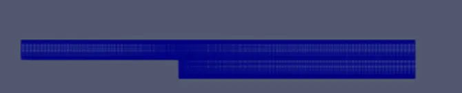
The velocity flow figure with grade point 0.2

The pressure flow figure with grade point 0.2

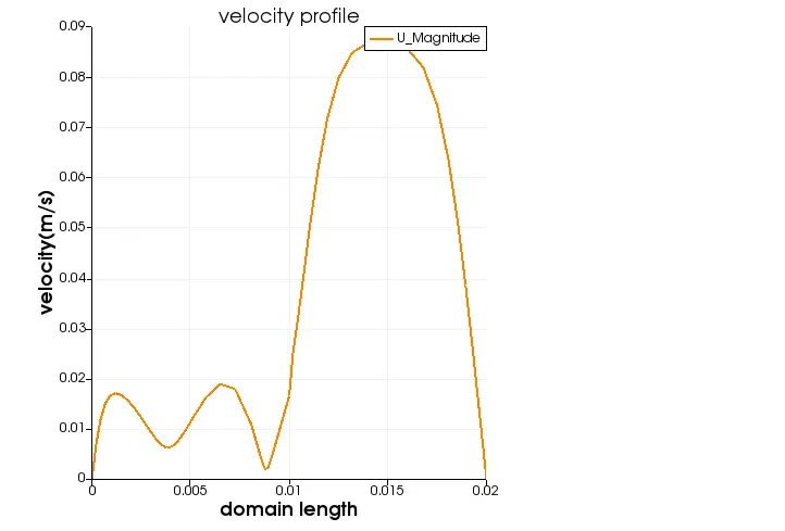
The plot for velocity at 0.085 for grading point 0.2
Conclusion :-
By changing the simple grading factor from value 0.2 to 1 the mesh become finner and solution becomes vary accurate
Overall the change in size of simple grading factor the reslut remains the same as the aprroximately
The excucation time is lower for lower meshing grading factor.