Week 8 - Simulation of a backward facing step in OpenFOAM
AIM:
- To simulate an incompressible – laminar – viscous flow through the backward facing step geometry.
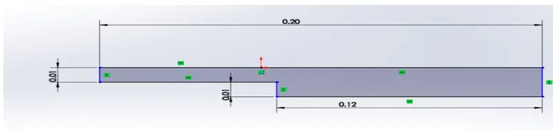
- To measure the velocity profile at 0.085 m from inlet of the geometry.
GIVEN:
CASE 1 - Simulate the flow without using any grading factor (i.e., GF = 1)
CASE 2 - Simulate the flow with grading factor of 0.2. The cells should be finer near the walls (including the step wall).
MESH SPECIFICATION
- Number of cells along the x direction (longer dimension) = 200
- Number of cells along the longer y direction = 20;
BOUNDARY CONDITION SPECIFICATION
The domain specifications are provided in the following figure
GEOMETRY CREATION:
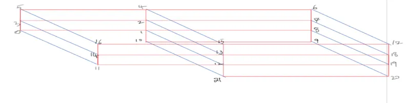
Let us consider creating the geometry using 5 blocks as shown in the figure below

The below sketch is used for finding the vertices for each block
PROCEDURE:
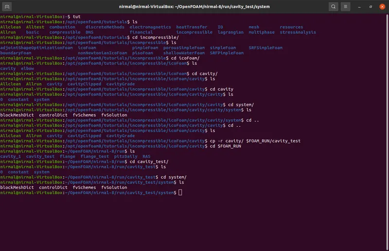
- Open the terminal in ubuntu by using Ctrl +Alt +T in the keyboard.
- We are going to simulate our problem in OpenFoam by using the tutorial file present in OpenFOAM.
- Type tut in the terminal to open the tutorials directory and type ls to list the files present inside the directory.
- As we are solving for incompressible flow we use the cd command to open the incompressible directory and ls to list the files inside the directory.
- The icoFoam solver is selected here because we are solving for laminar viscous flow that is present inside the incompressible directory.
- As per the requirement of geometry we are choosing the cavity folder.
- As we cannot make changes to tutorials directly we are making a copy of cavity directory to FOAM_RUN folder where we can makes changes to the problem.
- Inside the cavity folder we have initial folder, constsnt folder and the system folder.
- We are opening the system folder to make changes to the block mesh.
- The blockmeshdict file is opened to make changes . as it is a script file we use gedit command to edit the script. After making the changes the file is saved.
- To specify the simulation time the controldict script file is opened and made changesto it.
- After this our problem is all set we can now proceed with blockmesh command to deploy mesh and checkmesh command to check the quality of mesh.
- To run the simulation the icofoam solver name is just typed and the simulation will start running.
- The paraFoam command is used to view results in paraview to visualize the results and the variations.
CASE 1: simulation for the grading factor 1
BlockMeshDict:
/*--------------------------------*- C++ -*----------------------------------*\
  =========                 |
  \\      /  F ield         | OpenFOAM: The Open Source CFD Toolbox
   \\    /   O peration     | Website:  https://openfoam.org
    \\  /    A nd           | Version:  8
     \\/     M anipulation  |
\*---------------------------------------------------------------------------*/
FoamFile
{
    version     2.0;
    format      ascii;
    class       dictionary;
    object      blockMeshDict;
}
// * * * * * * * * * * * * * * * * * * * * * * * * * * * * * * * * * * * * * //

convertToMeters 1;

vertices
(
    (0 0 0)  //0
    (0.08 0 0)    //1
    (0.08 0.005 0)    //2
    (0 0.005 0)     //3
    (0.08 0.01 0)   //4
    (0 0.01 0)  //5
    (0.20 0.01 0)   //6
    (0.20 0.005 0)   //7
    (0.20 0 0)    //8
    (0.20 -0.01 0)   //9
    (0.08 -0.01 0)   //10
    (0 0 0.001)  //11
    (0.08 0 0.001)    //12
    (0.08 0.005 0.001)    //13
    (0 0.005 0.001)     //14
    (0.08 0.01 0.001)   //15
    (0 0.01 0.001)  //16
    (0.20 0.01 0.001)   //17
    (0.20 0.005 0.001)   //18
    (0.20 0 0.001)    //19
    (0.20 -0.01 0.001)   //20
    (0.08 -0.01 0.001)   //21
);

blocks
(
    hex (0 1 2 3 11 12 13 14) (80 5 1) simpleGrading (1 1 1)
    hex (3 2 4 5 14 13 15 16) (80 5 1) simpleGrading (1 1 1)
    hex (2 7 6 4 13 18 17 15) (120 5 1) simpleGrading (1 1 1)
    hex (1 8 7 2 12 19 18 13) (120 5 1) simpleGrading (1 1 1)
    hex (10 9 8 1 21 20 19 12) (120 10 1) simpleGrading (1 1 1)
);

edges
(
);

boundary
(
    inlet
    {
        type patch;
        faces
        (
            (0 11 14 3)
            (3 14 16 5)
        );
    }
    outlet
    {
        type patch;
        faces
        (
            (9 8 19 20)
            (8 7 18 19)
            (7 6 17 18)
        );
    }
    frontAndBack
    {
        type empty;
        faces
        (
            (0 3 2 1)
            (3 5 4 2)
            (2 4 6 7)
            (1 2 7 8)
            (10 1 8 9)
            (11 12 13 14)
            (14 13 15 16)
            (13 18 17 15)
            (12 19 18 13)
            (21 20 19 12)
        );
    }
    noslipwalls
    {
        type wall;
        faces
        (
            (5 16 15 4)
            (4 15 17 6)
            (0 1 12 11)
            (10 21 12 1)
            (10 9 20 21)
        );
    }
);

mergePatchPairs
(
);

// ************************************************************************* //- The vertices are defined in the BlockMeshDict file by making changes to the existing file.
- Here the model is splitted into five blocks having eight vertices each.
- The number of cells in x and y direction is also should be defined.
- The grading factor is defined as 1 in this case.
ControlDict:
/*--------------------------------*- C++ -*----------------------------------*\
  =========                 |
  \\      /  F ield         | OpenFOAM: The Open Source CFD Toolbox
   \\    /   O peration     | Website:  https://openfoam.org
    \\  /    A nd           | Version:  8
     \\/     M anipulation  |
\*---------------------------------------------------------------------------*/
FoamFile
{
    version     2.0;
    format      ascii;
    class       dictionary;
    location    "system";
    object      controlDict;
}
// * * * * * * * * * * * * * * * * * * * * * * * * * * * * * * * * * * * * * //

application     icoFoam;

startFrom       startTime;

startTime       0;

stopAt          endTime;

endTime         0.5;

deltaT          0.0001;

writeControl    timeStep;

writeInterval   20;

purgeWrite      0;

writeFormat     ascii;

writePrecision  6;

writeCompression off;

timeFormat      general;

timePrecision   6;

runTimeModifiable true;


// ************************************************************************* //- This script has the numerical schemes used for the simulation.
- The start and end time are defined in the code.
INITIAL SETUP:
FOR PRESSURE:
/*--------------------------------*- C++ -*----------------------------------*\
  =========                 |
  \\      /  F ield         | OpenFOAM: The Open Source CFD Toolbox
   \\    /   O peration     | Website:  https://openfoam.org
    \\  /    A nd           | Version:  8
     \\/     M anipulation  |
\*---------------------------------------------------------------------------*/
FoamFile
{
    version     2.0;
    format      ascii;
    class       volScalarField;
    object      p;
}
// * * * * * * * * * * * * * * * * * * * * * * * * * * * * * * * * * * * * * //

dimensions      [0 2 -2 0 0 0 0];

internalField   uniform 0;

boundaryField
{
    inlet
    {
        type            zeroGradient;
    }

    outlet
    {
        type            fixedValue;
        value           uniform 0;
    }

    frontAndBack
    {
        type            empty;
    }

    noslipwalls
    {
        type            zeroGradient;
    }
}

// ************************************************************************* //
FOR VELOCITY:
/*--------------------------------*- C++ -*----------------------------------*\
  =========                 |
  \\      /  F ield         | OpenFOAM: The Open Source CFD Toolbox
   \\    /   O peration     | Website:  https://openfoam.org
    \\  /    A nd           | Version:  8
     \\/     M anipulation  |
\*---------------------------------------------------------------------------*/
FoamFile
{
    version     2.0;
    format      ascii;
    class       volVectorField;
    object      U;
}
// * * * * * * * * * * * * * * * * * * * * * * * * * * * * * * * * * * * * * //

dimensions      [0 1 -1 0 0 0 0];

internalField   uniform (0.15 0 0);

boundaryField
{
    inlet
    {
        type            fixedValue;
        value           uniform (0.15 0 0);
    }

    outlet
    {
        type            zeroGradient;
    }

    noslipwalls
    {
        type            noSlip;
    }

    frontAndBack
    {
        type            empty;
    }
}

// ************************************************************************* //
RESULTS:
MESH:
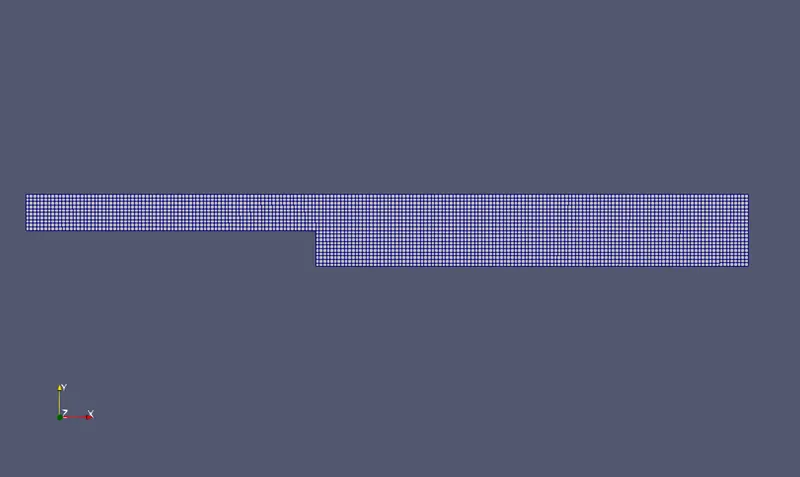
As the grading factor is 1 the mesh will be of same size and even throughout the model.
VELOCITY:
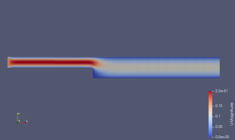
PRESSURE:
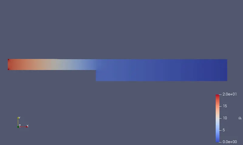
VELOCITY PROFILE:
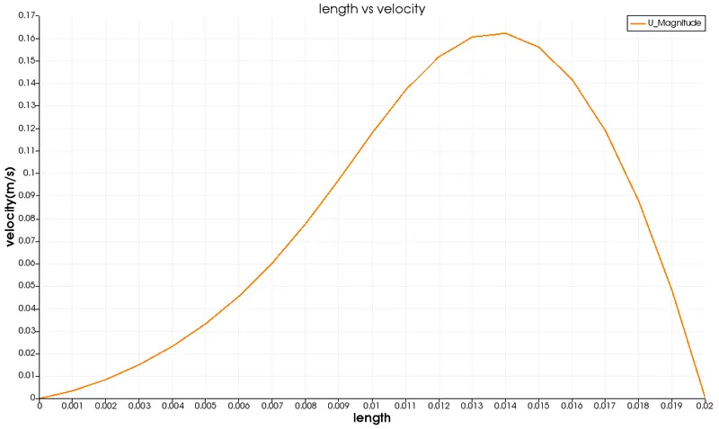
The velocity profile is shown at x = 0.085m.
PRESSURE PROFILE:
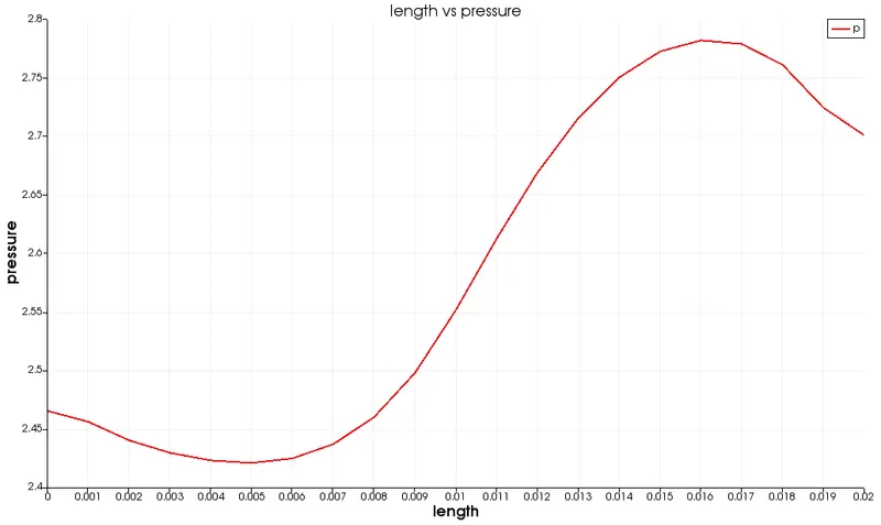
The pressure profile is shown at x = 0.085m.
CASE2: simulation for grading factor of 0.2
BlockMeshDict:
/*--------------------------------*- C++ -*----------------------------------*\
  =========                 |
  \\      /  F ield         | OpenFOAM: The Open Source CFD Toolbox
   \\    /   O peration     | Website:  https://openfoam.org
    \\  /    A nd           | Version:  8
     \\/     M anipulation  |
\*---------------------------------------------------------------------------*/
FoamFile
{
    version     2.0;
    format      ascii;
    class       dictionary;
    object      blockMeshDict;
}
// * * * * * * * * * * * * * * * * * * * * * * * * * * * * * * * * * * * * * //

convertToMeters 1;

vertices
(
    (0 0 0)  //0
    (0.08 0 0)    //1
    (0.08 0.005 0)    //2
    (0 0.005 0)     //3
    (0.08 0.01 0)   //4
    (0 0.01 0)  //5
    (0.20 0.01 0)   //6
    (0.20 0.005 0)   //7
    (0.20 0 0)    //8
    (0.20 -0.01 0)   //9
    (0.08 -0.01 0)   //10
    (0 0 0.001)  //11
    (0.08 0 0.001)    //12
    (0.08 0.005 0.001)    //13
    (0 0.005 0.001)     //14
    (0.08 0.01 0.001)   //15
    (0 0.01 0.001)  //16
    (0.20 0.01 0.001)   //17
    (0.20 0.005 0.001)   //18
    (0.20 0 0.001)    //19
    (0.20 -0.01 0.001)   //20
    (0.08 -0.01 0.001)   //21
);

blocks
(
    hex (0 1 2 3 11 12 13 14) (80 5 1) simpleGrading (1 5 1)
    hex (3 2 4 5 14 13 15 16) (80 5 1) simpleGrading (1 0.2 1)
    hex (2 7 6 4 13 18 17 15) (120 5 1) simpleGrading (5 0.2 1)
    hex (1 8 7 2 12 19 18 13) (120 5 1) simpleGrading (5 5 1)
    hex (10 9 8 1 21 20 19 12) (120 10 1) simpleGrading (5 5 1)
);

edges
(
);

boundary
(
    inlet
    {
        type patch;
        faces
        (
            (0 11 14 3)
            (3 14 16 5)
        );
    }
    outlet
    {
        type patch;
        faces
        (
            (9 8 19 20)
            (8 7 18 19)
            (7 6 17 18)
        );
    }
    frontAndBack
    {
        type empty;
        faces
        (
            (0 3 2 1)
            (3 5 4 2)
            (2 4 6 7)
            (1 2 7 8)
            (10 1 8 9)
            (11 12 13 14)
            (14 13 15 16)
            (13 18 17 15)
            (12 19 18 13)
            (21 20 19 12)
        );
    }
    noslipwalls
    {
        type wall;
        faces
        (
            (5 16 15 4)
            (4 15 17 6)
            (0 1 12 11)
            (10 21 12 1)
            (10 9 20 21)
        );
    }
);

mergePatchPairs
(
);

// ************************************************************************* //- The vertices are defined in the BlockMeshDict file by making changes to the existing file.
- Here the model is splitted into five blocks having eight vertices each.
- The number of cells in x and y direction is also should be defined.
- The grading factor is defined as 0.2 in this case to vary the no of grids to make easy capturing of the values.
ControlDict:
/*--------------------------------*- C++ -*----------------------------------*\
  =========                 |
  \\      /  F ield         | OpenFOAM: The Open Source CFD Toolbox
   \\    /   O peration     | Website:  https://openfoam.org
    \\  /    A nd           | Version:  8
     \\/     M anipulation  |
\*---------------------------------------------------------------------------*/
FoamFile
{
    version     2.0;
    format      ascii;
    class       dictionary;
    location    "system";
    object      controlDict;
}
// * * * * * * * * * * * * * * * * * * * * * * * * * * * * * * * * * * * * * //

application     icoFoam;

startFrom       startTime;

startTime       0;

stopAt          endTime;

endTime         0.5;

deltaT          0.0001;

writeControl    timeStep;

writeInterval   20;

purgeWrite      0;

writeFormat     ascii;

writePrecision  6;

writeCompression off;

timeFormat      general;

timePrecision   6;

runTimeModifiable true;


// ************************************************************************* //- This script has the numerical schemes used for the simulation.
- The start and end time are defined in the code.
RESULTS:
MESH:
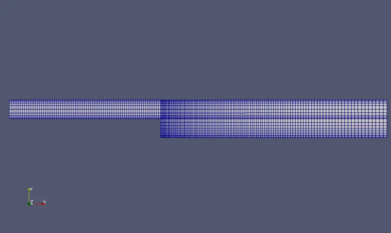
As the grading factor is 0.2 the mesh will not be of same size and even throughout the model.
VELOCITY:
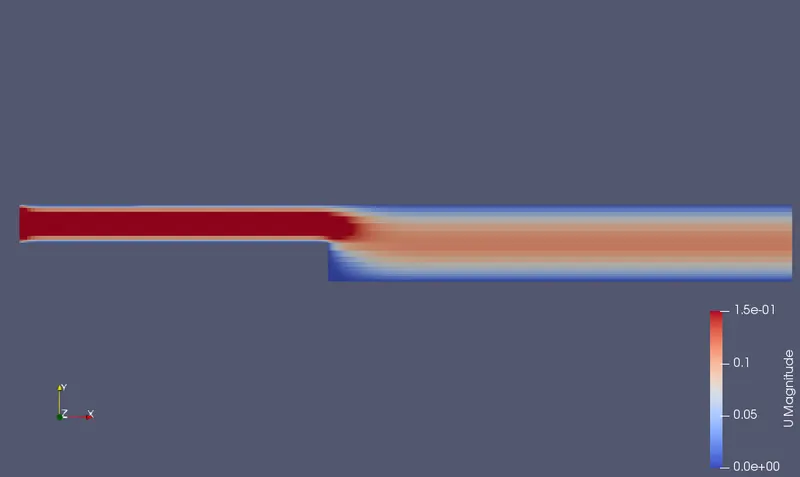
PRESSURE:
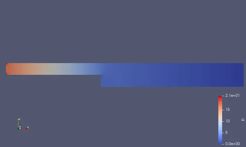
VELOCITY PROFILE:

The velocity profile is shown at x = 0.085m.
PRESSURE PROFILE:
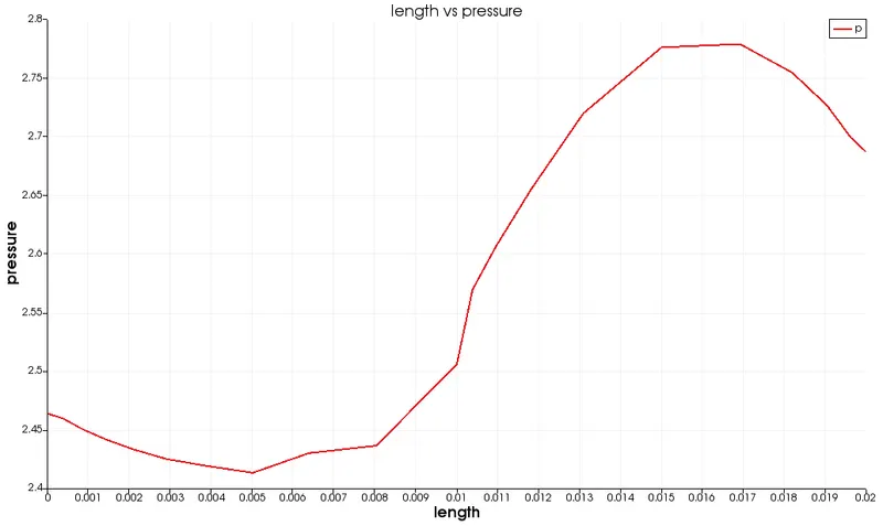
The pressure profile is shown at x = 0.085m.
CONCLUSION:
- If we vary the mesh quality and the grading factor it will have a straight impact on the velocity and pressure.
- The lesser grading factor gives finer mesh and the high grading factor gives larger mesh.