Simulation of a backward facing step in OpenFOAM (ITCFDUML&OF/Challenge/Week8)
AIM : To simulate a 2-D, Incompressible, Viscous, Laminar Flow over a Backward Facing Step in OpenFOAM.
OBJECTIVE :
- Simulate an incompressible-laminar-viscous flow through the backward facing step geometry
- Should perform a transient simulation. The solver can be chosen based on the described physics of the flow, and choose the inlet velocity such that the flow is laminar.
-
Perform 2 case studies as described below and compare the results -
Case 1 - Simulate the flow without using any grading factor (i.e., GF = 1)
Case 2 - Simulate the flow with grading factor of 0.2. The cells should be finer near the walls (including the step wall)
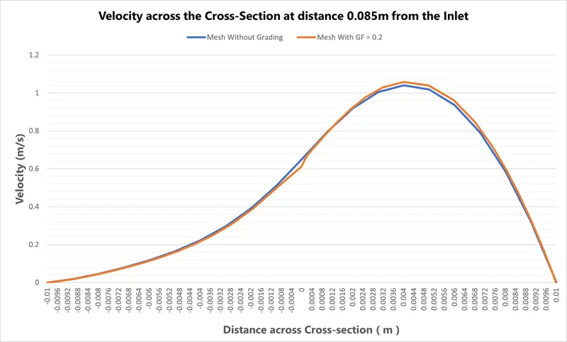
- Measure and compare the velocity profile at 0.085m from the inlet of geometry for both case studies.
- Explain why Grading/Growth factor is essential for meshing.
THEORY :
Backward Facing Step (BFS) is widely known for its application in the studies on internal flows. Flow separation is a common and interesting phenomenon in fluid mechanics with significant effects in practical application. Thus, it has been the focus of intensive study for many years. A standard set of simple geometric configurations including the flow in a pipe with a sudden expansion, the flow in a pipe with an obstruction such as an orifice, the flow over an obstacle in a channel and the flow in a channel with a sudden expansion, has been proposed as representative test cases.
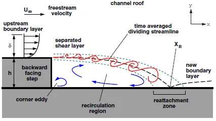
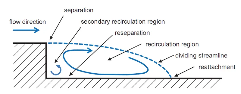
Backward Facing Step is one of the vital flow geometry for investigating separated flows. In this the flow enters from the inlet passes through a constant area duct and exits into another duct having a cross-sectional area larger than the inlet duct. As this occurs, a recirculation zone occurs at the 'step’ of the duct having a larger cross-sectional area. The flow separation is caused due to the sudden changes in the geometry. This creates a zone of re-circulation and a point of flow reattachment. Even though it is a simple and common problem but it has a wide scope, which makes it a building block for a variety of applications. This recirculation depends on the Reynolds number of the flow, size of the step, expansion ratio, aspect ratio (in 3D case), etc.
Schematics of the Flow over a Backward Facing Step Geometry is shown in the diagram below, -
STEPS :
The main outline for per forming the simulation is as follows -
- Type of Porblem and Choosing Solver
- Creating geometry
- Meshing
- Defining Initial Conditions and Boundary condition
- Post-processing – plotting results
SIMULATION SETUP :
Following are the sequence of the steps for performing the simulation of BFS using OpenFOAM -
1. Choosing Solver Based on the Type of the Problem -
In this project case study, major physics the fluid flow problem accounts is laminar incompressible and viscous flow properties.
In openfoam, we basically choose solver from the already validate tutorial simulation database for the type of problem and then modify the simulation setup as per our problems geometry and conditions inorder to simulate a problem.
Like here for our problem, we will choose icoFoam solver i.e. basically incompressible solver, in which cavity problem is taken as base case in which files are modified for geometry, boundary and initial conditions.
Locating the tutorial problem similiar to our problem, which can solved by the same solver, and with slight modification in the setup.
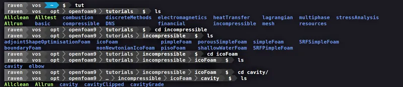
Now copy cavity folder from FOAM_TUTORIALS directory to the FOAM_RUN directory and rename it from the following command:
cp -r cavity/ $FOAM_RUN/bfs_analysis
Since, the tutorials are the essentials for the OpenFOAM software, therefore it does not allow to modify the problem case inside the OpenFOAM tutorials directory. Therefore it is required to always copy the respective problem tutorial folder to another directory(usually FOAM_RUN) before modifying the case setup for the simulation.
2. Geometry and Meshing
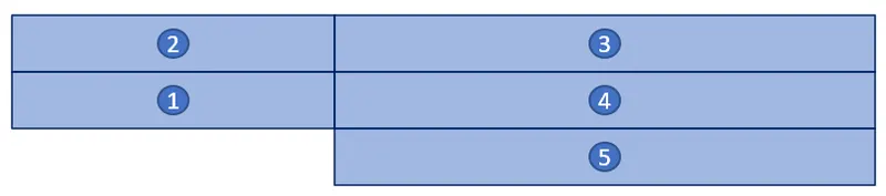
The given Geometry and Dimensions of the geometry, for this problem is shown below -

Dimensions of the Geometry
Volumetric Block Cells Distribution
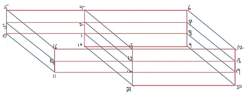
Indexing the end-points of edges of cells
Meshing -
Meshing is the process in which the continuous geometric space of an object is broken down into very small pieces of shapes to properly define the physical shape of the object. The more detailed a mesh is, the more accurate the CAD model will be, allowing for high fidelity simulations. Meshing, also known as mesh generation, is the process of generating a two-dimensional and three-dimensional grid; it is dividing complex geometries into elements that can be used to discretize a domain. Computers cannot solve simulations on the CAD model’s actual geometry shape as the governing equations cannot be applied to an arbitrary shape. Mesh elements allow governing equations to be solved on predictably shaped and mathematically defined volumes.
Grading Factor - In order to see the desired phenomenon in particular region of interest (Usaully most of the time to capture boundary layers near the wall) the grid size need to be kept small so to achieve this, in OpenFOAM the concept of ‘grading’ is used. Same concept/tool in ANSYS is called
So, Grading factor (GF) is ratio of length of end cell to the start cell.
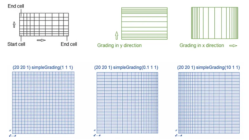
In OpenFOAM, the geometry and meshing parameters are defined in the blockMeshDict file. So inorder to define geometry for our problem we need to edit the blockMeshDict file using a Text Editor. The Edited BlockMesh Dict Files for our problem for both the cases is shown below -
a) blockMeshDict File for No GF(Grading Factor) i.e. GF = 1 -
/*--------------------------------*- C++ -*----------------------------------*
  =========                 |
        /  F ield         | OpenFOAM: The Open Source CFD Toolbox
       /   O peration     | Website:  https://openfoam.org
      /    A nd           | Version:  9
     /     M anipulation  |
*---------------------------------------------------------------------------*/
FoamFile
{
    format      ascii;
    class       dictionary;
    object      blockMeshDict;
}
// * * * * * * * * * * * * * * * * * * * * * * * * * * * * * * * * * * * * * //

convertToMeters 1;

vertices
(
    /* 0 */  (0 0 0)
    /* 1 */  (0.08 0 0)
    /* 2 */  (0.08 0.005 0)
    /* 3 */  (0 0.005 0)
    /* 4 */  (0.08 0.01 0)
    /* 5 */  (0 0.01 0)
    /* 6 */  (0.20 0.01 0)
    /* 7 */  (0.20 0.005 0)
    /* 8 */  (0.20 0 0)
    /* 9 */  (0.20 -0.01 0)
    /* 10 */ (0.08 -0.01 0)

    /* 11 */ (0 0 0.001)
    /* 12 */ (0.08 0 0.001)
    /* 13 */ (0.08 0.005 0.001)
    /* 14 */ (0 0.005 0.001)
    /* 15 */ (0.08 0.01 0.001)
    /* 16 */ (0 0.01 0.001)
    /* 17 */ (0.20 0.01 0.001)
    /* 18 */ (0.20 0.005 0.001)
    /* 19 */ (0.20 0 0.001)
    /* 20 */ (0.20 -0.01 0.001)
    /* 21 */ (0.08 -0.01 0.001)

);

blocks
(
    /* block-1 */   hex (0 1 2 3 11 12 13 14)  (80 5 1)  simpleGrading (1 1 1)
    /* block-2 */   hex (3 2 4 5 14 13 15 16)  (80 5 1)  simpleGrading (1 1 1)
    /* block-3 */   hex (2 7 6 4 13 18 17 15)  (120 5 1) simpleGrading (1 1 1)
    /* block-4 */   hex (1 8 7 2 12 19 18 13)  (120 5 1) simpleGrading (1 1 1)
    /* block-5 */   hex (10 9 8 1 21 20 19 12) (120 10 1) simpleGrading (1 1 1)
);

edges
(
);

boundary
(
    inlet
    {
        type patch;
        faces
        (
            (0 11 14 3)
            (3 14 16 5)
        );
    }

    outlet
    {
        type patch;
        faces
        (
            (17 18 7 6)
            (18 19 8 7)
            (19 20 9 8)
        );
    }

    fixedWalls
    {
        type wall;
        faces
        (
            (0 1 12 11)
            (10 21 12 1)
            (10 9 20 21)

            (5 16 15 4)
            (4 15 17 6)
        );
    }

    frontAndBack
    {
        type empty;
        faces
        (
           //Back Faces
            (0 3 2 1)
            (3 5 4 2)
            (2 4 6 7)
            (1 2 7 8)
            (10 1 8 9)

           //Front Faces
            (11 12 13 14)
            (14 13 15 16)
            (13 18 17 15)
            (12 19 18 13)
            (21 20 19 12)
        );
    }
);

mergePatchPairs
(
);

// ************************************************************************* //
b) blockMeshDict File for GF = 0.2 -
/*--------------------------------*- C++ -*----------------------------------*
  =========                 |
        /  F ield         | OpenFOAM: The Open Source CFD Toolbox
       /   O peration     | Website:  https://openfoam.org
      /    A nd           | Version:  9
     /     M anipulation  |
*---------------------------------------------------------------------------*/
FoamFile
{
    format      ascii;
    class       dictionary;
    object      blockMeshDict;
}
// * * * * * * * * * * * * * * * * * * * * * * * * * * * * * * * * * * * * * //

convertToMeters 1;

vertices
(
    /* 0 */  (0 0 0)
    /* 1 */  (0.08 0 0)
    /* 2 */  (0.08 0.005 0)
    /* 3 */  (0 0.005 0)
    /* 4 */  (0.08 0.01 0)
    /* 5 */  (0 0.01 0)
    /* 6 */  (0.20 0.01 0)
    /* 7 */  (0.20 0.005 0)
    /* 8 */  (0.20 0 0)
    /* 9 */  (0.20 -0.01 0)
    /* 10 */ (0.08 -0.01 0)

    /* 11 */ (0 0 0.001)
    /* 12 */ (0.08 0 0.001)
    /* 13 */ (0.08 0.005 0.001)
    /* 14 */ (0 0.005 0.001)
    /* 15 */ (0.08 0.01 0.001)
    /* 16 */ (0 0.01 0.001)
    /* 17 */ (0.20 0.01 0.001)
    /* 18 */ (0.20 0.005 0.001)
    /* 19 */ (0.20 0 0.001)
    /* 20 */ (0.20 -0.01 0.001)
    /* 21 */ (0.08 -0.01 0.001)

);

blocks
(
    /* block-1 */   hex (0 1 2 3 11 12 13 14)  (160 10 1) simpleGrading (0.2 5 1)
    /* block-2 */   hex (3 2 4 5 14 13 15 16)  (160 10 1) simpleGrading (0.2 0.2 1)
    /* block-3 */   hex (2 7 6 4 13 18 17 15)  (240 10 1) simpleGrading (5 0.2 1)
    /* block-4 */   hex (1 8 7 2 12 19 18 13)  (240 10 1) simpleGrading (5 5 1)
    /* block-5 */   hex (10 9 8 1 21 20 19 12) (240 20 1) simpleGrading (5 5 1)
);

edges
(
);

boundary
(
    inlet
    {
        type patch;
        faces
        (
            (0 11 14 3)
            (3 14 16 5)
        );
    }

    outlet
    {
        type patch;
        faces
        (
            (17 18 7 6)
            (18 19 8 7)
            (19 20 9 8)
        );
    }

    fixedWalls
    {
        type wall;
        faces
        (
            (0 1 12 11)
            (10 21 12 1)
            (10 9 20 21)

            (5 16 15 4)
            (4 15 17 6)
        );
    }

    frontAndBack
    {
        type empty;
        faces
        (
           //Back Faces
            (0 3 2 1)
            (3 5 4 2)
            (2 4 6 7)
            (1 2 7 8)
            (10 1 8 9)

           //Front Faces
            (11 12 13 14)
            (14 13 15 16)
            (13 18 17 15)
            (12 19 18 13)
            (21 20 19 12)
        );
    }
);

mergePatchPairs
(
);

// ************************************************************************* //
3. Simulation Run Setup -
This is basically, where we specify how much long the simulation will be like the start and end time, the time step size (dt), etc. , in OpenFOAM this is specified in the controlDict file.
The Time-step size is choosen with respect to keeping the stability of simulation in the mind. In the current problem we have chosen 'dt' based on the CFL criteria, i.e. based on the velocity and mesh cell size.
a) controlDict file for No GF(Grading Factor) i.e. GF = 1 -
/*--------------------------------*- C++ -*----------------------------------*
  =========                 |
        /  F ield         | OpenFOAM: The Open Source CFD Toolbox
       /   O peration     | Website:  https://openfoam.org
      /    A nd           | Version:  9
     /     M anipulation  |
*---------------------------------------------------------------------------*/
FoamFile
{
    format      ascii;
    class       dictionary;
    location    "system";
    object      controlDict;
}
// * * * * * * * * * * * * * * * * * * * * * * * * * * * * * * * * * * * * * //

application     icoFoam;

startFrom       startTime;

startTime       0;

stopAt          endTime;

endTime         2;

deltaT          0.0005;

writeControl    timeStep;

writeInterval   20;

purgeWrite      0;

writeFormat     ascii;

writePrecision  6;

writeCompression off;

timeFormat      general;

timePrecision   6;

runTimeModifiable true;


// ************************************************************************* //
b) controlDict File for GF = 0.2 -
/*--------------------------------*- C++ -*----------------------------------*
  =========                 |
        /  F ield         | OpenFOAM: The Open Source CFD Toolbox
       /   O peration     | Website:  https://openfoam.org
      /    A nd           | Version:  9
     /     M anipulation  |
*---------------------------------------------------------------------------*/
FoamFile
{
    format      ascii;
    class       dictionary;
    location    "system";
    object      controlDict;
}
// * * * * * * * * * * * * * * * * * * * * * * * * * * * * * * * * * * * * * //

application     icoFoam;

startFrom       startTime;

startTime       0;

stopAt          endTime;

endTime         0.1;

deltaT          0.00001;

writeControl    timeStep;

writeInterval   40;

purgeWrite      0;

writeFormat     ascii;

writePrecision  6;

writeCompression off;

timeFormat      general;

timePrecision   6;

runTimeModifiable true;


// ************************************************************************* //
4. Initial and Boundary Conditions -
Initial and boundary conditions are define in the 'U'(Velocity) and 'P'(Pressure) script files inside the 0 folder.
Since the flow should be Laminar therefore, U = 1 m/s
These files will remain the same for every analysis of different mesh grading factor.
The boundary conditions provided were as follows: a ‘constant velocity profile’ was assigned to the inlet face, ‘zero gradient’ was assigned to the outlet face, and wall 'no-slip' was assigned to both lower & upper fixedwall faces. Only the front & back faces were designated as ‘empty.’
U -
/*--------------------------------*- C++ -*----------------------------------*
  =========                 |
        /  F ield         | OpenFOAM: The Open Source CFD Toolbox
       /   O peration     | Website:  https://openfoam.org
      /    A nd           | Version:  9
     /     M anipulation  |
*---------------------------------------------------------------------------*/
FoamFile
{
    format      ascii;
    class       volVectorField;
    object      U;
}
// * * * * * * * * * * * * * * * * * * * * * * * * * * * * * * * * * * * * * //

dimensions      [0 1 -1 0 0 0 0];

internalField   uniform (0 0 0);

boundaryField
{
    inlet
    {
        type            fixedValue;
        value           uniform (1 0 0);
    }

    outlet
    {
        type            zeroGradient;
    }


    fixedWalls
    {
        type            noSlip;
    }

    frontAndBack
    {
        type            empty;
    }
}

// ************************************************************************* //
P -
/*--------------------------------*- C++ -*----------------------------------*
  =========                 |
        /  F ield         | OpenFOAM: The Open Source CFD Toolbox
       /   O peration     | Website:  https://openfoam.org
      /    A nd           | Version:  9
     /     M anipulation  |
*---------------------------------------------------------------------------*/
FoamFile
{
    format      ascii;
    class       volScalarField;
    object      p;
}
// * * * * * * * * * * * * * * * * * * * * * * * * * * * * * * * * * * * * * //

dimensions      [0 2 -2 0 0 0 0];

internalField   uniform 0;

boundaryField
{
    inlet
    {
        type            zeroGradient;
    }

    outlet
    {
        type            fixedValue;
        value           uniform 0;
    }

    fixedWalls
    {
        type            zeroGradient;
    }

    frontAndBack
    {
        type            empty;
    }
}

// ************************************************************************* //
Transport Properties-
The constant folder contains transportProperties which contains the properties of the fluid. In our case, the fluid is an incompressible newtonian fluid, i.e. here the viscosity of the fluid is defined. Here in the script file, 'nu' is the Dynamic Viscosity(`nu`) of the fluid.
Since, we are considering fluid as water, therefore we are taking, nu = 0.01 `Ns`/`m^2`
transportProperties -
/*--------------------------------*- C++ -*----------------------------------*
  =========                 |
        /  F ield         | OpenFOAM: The Open Source CFD Toolbox
       /   O peration     | Website:  https://openfoam.org
      /    A nd           | Version:  9
     /     M anipulation  |
*---------------------------------------------------------------------------*/
FoamFile
{
    format      ascii;
    class       dictionary;
    location    "constant";
    object      transportProperties;
}
// * * * * * * * * * * * * * * * * * * * * * * * * * * * * * * * * * * * * * //

nu              [0 2 -1 0 0 0 0] 0.01;


// ************************************************************************* //
FVSchemes & FVSolution :
Along with the blockMeshDict and controlDict files there are also fvschemes and fvSolution files in the system folder.
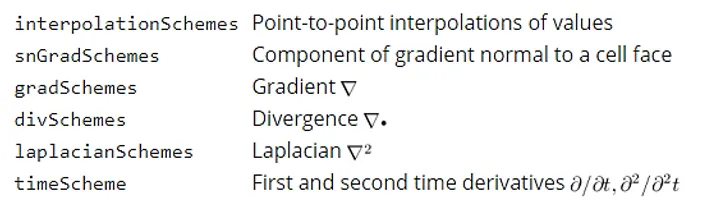
fvSchemes script file sets the numerical schemes for terms, such as derivatives in equations, that are calculated during a simulation.
The set of terms, for which numerical schemes must be specified, are subdivided within the fvSchemes dictionary into the categories below -
fvSchemes -
/*--------------------------------*- C++ -*----------------------------------*
  =========                 |
        /  F ield         | OpenFOAM: The Open Source CFD Toolbox
       /   O peration     | Website:  https://openfoam.org
      /    A nd           | Version:  9
     /     M anipulation  |
*---------------------------------------------------------------------------*/
FoamFile
{
    format      ascii;
    class       dictionary;
    location    "system";
    object      fvSchemes;
}
// * * * * * * * * * * * * * * * * * * * * * * * * * * * * * * * * * * * * * //

ddtSchemes
{
    default         Euler;
}

gradSchemes
{
    default         Gauss linear;
    grad(p)         Gauss linear;
}

divSchemes
{
    default         none;
    div(phi,U)      Gauss linear;
}

laplacianSchemes
{
    default         Gauss linear orthogonal;
}

interpolationSchemes
{
    default         linear;
}

snGradSchemes
{
    default         orthogonal;
}


// ************************************************************************* //
The equation solvers, tolerances and algorithms are controlled from the fvSolution dictionary in the system directory. Below in our problem, set of entries from the fvSolution dictionary required for the icoFoam solver.
fvSolution contains a set of subdictionaries that are specific to the solver being run. However, there is a small set of standard subdictionaries that cover most of those used by the standard solvers. These subdictionaries include solvers, relaxationFactors, PISO and SIMPLE which are described in the remainder of this section.
fvSolution -
/*--------------------------------*- C++ -*----------------------------------*
  =========                 |
        /  F ield         | OpenFOAM: The Open Source CFD Toolbox
       /   O peration     | Website:  https://openfoam.org
      /    A nd           | Version:  9
     /     M anipulation  |
*---------------------------------------------------------------------------*/
FoamFile
{
    format      ascii;
    class       dictionary;
    location    "system";
    object      fvSolution;
}
// * * * * * * * * * * * * * * * * * * * * * * * * * * * * * * * * * * * * * //

solvers
{
    p
    {
        solver          PCG;
        preconditioner  DIC;
        tolerance       1e-06;
        relTol          0.05;
    }

    pFinal
    {
        $p;
        relTol          0;
    }

    U
    {
        solver          smoothSolver;
        smoother        symGaussSeidel;
        tolerance       1e-05;
        relTol          0;
    }
}

PISO
{
    nCorrectors     2;
    nNonOrthogonalCorrectors 0;
    pRefCell        0;
    pRefValue       0;
}


// ************************************************************************* //
POST-POSTPROCESSING & RESULTS -
I. Results of Simulation without using any Grading Factor (i.e., GF = 1)
Mesh Generated -

Velocity Contour -

Pressure Contour -

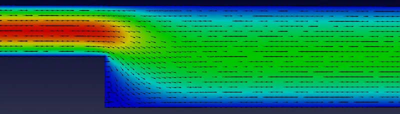
Visualizing Re-Circulation and Re-Attachment regions via Velocity Vectors -

II. Results of Simulation with grading factor of 0.2 -
Mesh Generated -

Velocity Contour -
Pressure Contour -

Visualizing Re-Circulation and Re-Attachment regions via Velocity Vectors -

COMPARISON OF VELOCITY PROFILES FOR BOTH CASES AT CROSS-SECTIONS DIFFERENT LOCATIONS IN X-DIRECTION -
1. Location at X = 0.04 m -

2. Location at X = 0.085 m -

3. Location at X = 0.14 m -

RESULTS & CONCLUSION :
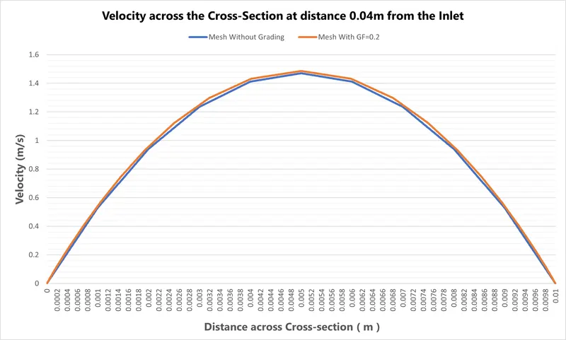
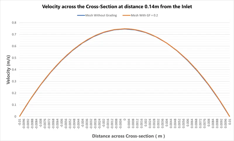
- After Plotting the velocity profile graphs at x = 0.04m and x = 0.14m, it can be seen that the velocity at the walls is zero, whereas the velocity at the center is maximum. This is due to the no-slip boundary condition at the walls i.e. viscous effects are considered.
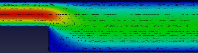
- The velocity profile graphs obtained at x = 0.085 m, for the different meshing grading factors we can see the significant variations in the velocity profile across the Cross-Section. As the mesh's cell size is smaller, i.e., for finer mesh, we can visualize the accurate output. As our fluid is viscous, thus it offers resistance between the layers; therefore, the velocity should be maximum at the center, but here we can see that the peak is at the right side of the curve. This can be explained due to the sudden change in the cross-section of the nozzle. Thus the vortices of re-circulation are formed due to the sudden change, the low-pressure area is generated in that area, and the velocity in that area is low due to the liquid portion moving backwards for the re-circulation vortex.
- We can also see in the Contour Plot with velocity vectors, that for the the mesh with finer/graded cells at the Backward Facing Step have more accurate visualization of the Re-Circulation and Re-attachment regions of the flow.
Significance of graded Mesh:
- In the newtonian flow, due to viscosity of fluid there are viscous forces generated across the fluid-surface contact, acting against the flow of the fluid resulting shear stresses among the fluid element. The velocity of the fluid elements closest to wall surface is almost zero and the velocity at the center of the cross-section is the highest. With grading, these wall boundary layer effects are captured well.
- With grading, the mesh is coarse in the middle region, which makes the velocity curves slightly distorted, while the curve obtained by without grading mesh is pretty smooth all over the area.
- For better and accurate results, we should have finer mesh near the walls. But as we increase the grading for the finer mesh near the walls, the time taken for solving the whole simulation will also be increased. This is due to, since the min. space-step size of the cell is reduced therefore inorder to maintain the stability of the simulation we have also greatly reduce the time-step size for simulation to perform for the same velocity (or other physics conditions).
REFERENCE :
https://www.openfoam.com/documentation/user-guide
https://cfd-training.com/2019/04/06/backward-facing-step-laminar-flow/