Week 8 - Simulation of a backward facing step in OpenFOAM
OBJECTIVE :
To simulate an incompressible-laminar-viscous flow through the backward facing step geometry and perform a transient simulation.
Case 1 - Simulate the flow without using any grading factor (i.e., GF = 1)
Case 2 - Simulate the flow with grading factor of 0.2. The cells should be finer near the walls (includig the step wall).
STEPS INVOLVED :
1) Select solver tutorial
2) Create geometry and Mesh
3)Assign initial and boundary conditions
4)Run solver
5) Post-Process results.
SELECT SOLVER :
As given problem is of Newtonian incopressible laminar flow with no friction losses we need to solve incompressible Navier Stokes equations and there is no envolment of temperature or heat we do not need to solve enegy equation.
icoFoam is the solver which solves incompressible Navier Stokes equations.
CREAT GEOMETRY AND MESH :
In the system directory there is blockMeshDict file where we create geometry in the form of blocks by defining the vertices as shown below.
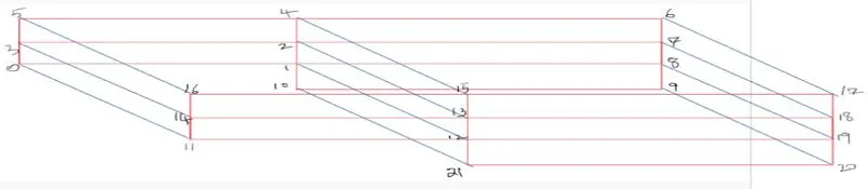
We divide each block into number of cells in meshing process.
- Number of cells along the x direction (longer dimension) = 200
- Number of cells along the longer y direction = 20
Mesh can be made fine at any edge by giving grading factor
`GF=(size__ of__ la st__ cell)/(size__ of__ first__ cell)`
BlockMesh Code :
/*--------------------------------*- C++ -*----------------------------------*\
  =========                 |
  \\      /  F ield         | OpenFOAM: The Open Source CFD Toolbox
   \\    /   O peration     | Website:  https://openfoam.org
    \\  /    A nd           | Version:  9
     \\/     M anipulation  |
\*---------------------------------------------------------------------------*/
FoamFile
{
    format      ascii;
    class       dictionary;
    object      blockMeshDict;
}
// * * * * * * * * * * * * * * * * * * * * * * * * * * * * * * * * * * * * * //

convertToMeters 1;

vertices
(
    (0 0 0) //0
    (0.08 0 0) //1
    (0.08 0.005 0) //2
    (0 0.005 0) //3
    (0.08 0.01 0) //4
    (0 0.01 0) //5
    (0.2 0.01 0) //6
    (0.2 0.005 0) //7
    (0.2 0 0) //8
    (0.2 -0.01 0) //9
    (0.08 -0.01 0) //10
    (0 0 0.001) //11
    (0.08 0 0.001) //12
    (0.08 0.005 0.001) //13
    (0 0.005 0.001) //14
    (0.08 0.01 0.001) //15
    (0 0.01 0.001) //16
    (0.2 0.01 0.001) //17
    (0.2 0.005 0.001) //18
    (0.2 0 0.001) //19
    (0.2 -0.01 0.001) //20
    (0.08 -0.01 0.001) //21
);

blocks
(
    hex (0 1 2 3 11 12 13 14) (80 5 1) simpleGrading (0.2 1 1)
    hex (3 2 4 5 14 13 15 16) (80 5 1) simpleGrading (0.2 1 1)
    hex (2 7 6 4 13 18 17 15) (120 5 1) simpleGrading (5 1 1)
    hex (1 8 7 2 12 19 18 13) (120 5 1) simpleGrading (5 1 1)
    hex (10 9 8 1 21 20 19 12) (120 10 1) simpleGrading (5 1 1)
);

edges
(
);

boundary
(
    inlet
    {
        type patch;
        faces
        (
            (0 11 14 3)
            (3 14 16 5)
        );
    }
    outlet
    {
        type patch;
        faces
        (
            (9 8 19 20)
            (8 7 18 19)
            (7 6 17 18)
        );
    }
    frontAndBack
    {
        type empty;
        faces
        (
            (0 3 2 1)
            (11 12 13 14)
            (3 5 4 2)
            (13 15 16 14)
            (2 4 6 7)
            (13 18 17 15)
            (1 2 7 8)
            (12 19 18 13)
            (10 1 8 9)
            (21 20 19 12)
        );
    }
    noslipwall
    {
        type wall;
        faces
        (
            (4 5 16 15)
            (4 15 17 6)
            (0 1 12 11)
            (9 20 21 10)
            (1 10 21 12)
        );
    }
);

mergePatchPairs
(
);

// ************************************************************************* //

fig. Mesh with no grading factor
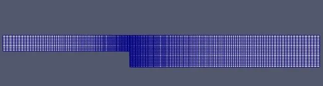
fig. Mesh with grading factor 0.2 (fine mesh near step)
Now time step size is changed in contlorDict file here we difine start time , end time , time steo size so that it can satify criteria of stability. i.e.
Courant Number < 0.5
`△t=(C*△x)/v`
controlDict Code :
/*--------------------------------*- C++ -*----------------------------------*\
  =========                 |
  \\      /  F ield         | OpenFOAM: The Open Source CFD Toolbox
   \\    /   O peration     | Website:  https://openfoam.org
    \\  /    A nd           | Version:  9
     \\/     M anipulation  |
\*---------------------------------------------------------------------------*/
FoamFile
{
    format      ascii;
    class       dictionary;
    location    "system";
    object      controlDict;
}
// * * * * * * * * * * * * * * * * * * * * * * * * * * * * * * * * * * * * * //

application     icoFoam;

startFrom       startTime;

startTime       0;

stopAt          endTime;

endTime         0.5;

deltaT          0.0001;

writeControl    timeStep;

writeInterval   20;

purgeWrite      0;

writeFormat     ascii;

writePrecision  6;

writeCompression off;

timeFormat      general;

timePrecision   6;

runTimeModifiable true;


// ************************************************************************* //
INITIAL AND BOUNDARY CONDITION :
Initials conditions are set at the '0' directory where we find files for pressure and velocity.
x-component of velocity id specified such that Reynold number remain in laminar regim.
`Re=(ρvD)/μ`
Defining kinematic viscosity :
/*--------------------------------*- C++ -*----------------------------------*\
  =========                 |
  \\      /  F ield         | OpenFOAM: The Open Source CFD Toolbox
   \\    /   O peration     | Website:  https://openfoam.org
    \\  /    A nd           | Version:  9
     \\/     M anipulation  |
\*---------------------------------------------------------------------------*/
FoamFile
{
    format      ascii;
    class       dictionary;
    location    "constant";
    object      transportProperties;
}
// * * * * * * * * * * * * * * * * * * * * * * * * * * * * * * * * * * * * * //

nu              [0 2 -1 0 0 0 0] 1e-5;


// ************************************************************************* //
Defining boundary and intial condition for velocity ;
/*--------------------------------*- C++ -*----------------------------------*\
  =========                 |
  \\      /  F ield         | OpenFOAM: The Open Source CFD Toolbox
   \\    /   O peration     | Website:  https://openfoam.org
    \\  /    A nd           | Version:  9
     \\/     M anipulation  |
\*---------------------------------------------------------------------------*/
FoamFile
{
    format      ascii;
    class       volVectorField;
    object      U;
}
// * * * * * * * * * * * * * * * * * * * * * * * * * * * * * * * * * * * * * //

dimensions      [0 1 -1 0 0 0 0];

internalField   uniform (0.15 0 0);

boundaryField
{
    inlet
    {
        type            fixedValue;
        value           uniform (0.15 0 0);
    }

    outlet
    {
        type            zeroGradient;
    }

    frontAndBack
    {
        type            empty;
    }

    noslipwall
    {
        type            noSlip;
    }
}

// ************************************************************************* //
Defining intial and bounadry condition for pressure :
/*--------------------------------*- C++ -*----------------------------------*\
  =========                 |
  \\      /  F ield         | OpenFOAM: The Open Source CFD Toolbox
   \\    /   O peration     | Website:  https://openfoam.org
    \\  /    A nd           | Version:  9
     \\/     M anipulation  |
\*---------------------------------------------------------------------------*/
FoamFile
{
    format      ascii;
    class       volScalarField;
    object      p;
}
// * * * * * * * * * * * * * * * * * * * * * * * * * * * * * * * * * * * * * //

dimensions      [0 2 -2 0 0 0 0];

internalField   uniform 0;

boundaryField
{
    inlet
    {
        type            zeroGradient;
    }

    outlet
    {
        type            fixedValue;
        value           uniform 0;
    }

    frontAndBack
    {
        type            empty;
    }

    noslipwall
    {
        type            zeroGradient;
    }
}

// ************************************************************************* //
POST PROCESSING :
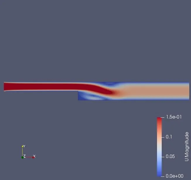
Above figure shows velocity variation in domain at end time. Here as area increases at step velocity decreases.
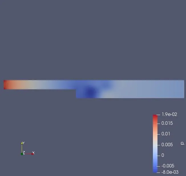
above figure shows the pressure variation in dommaint atend time.
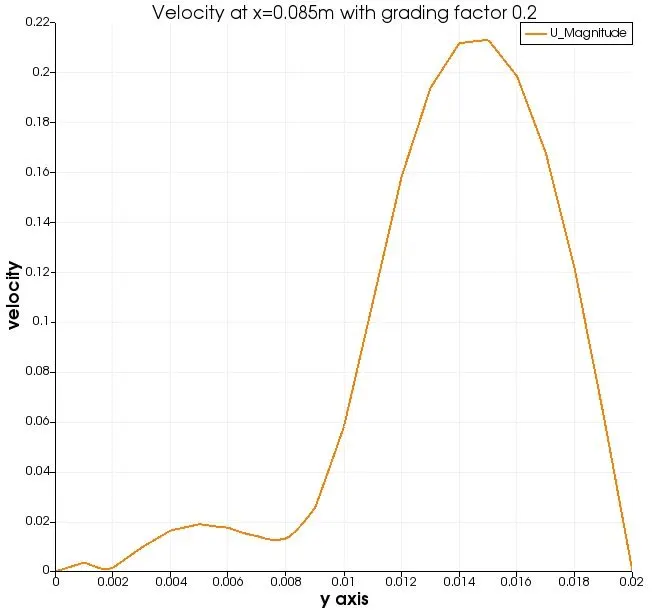
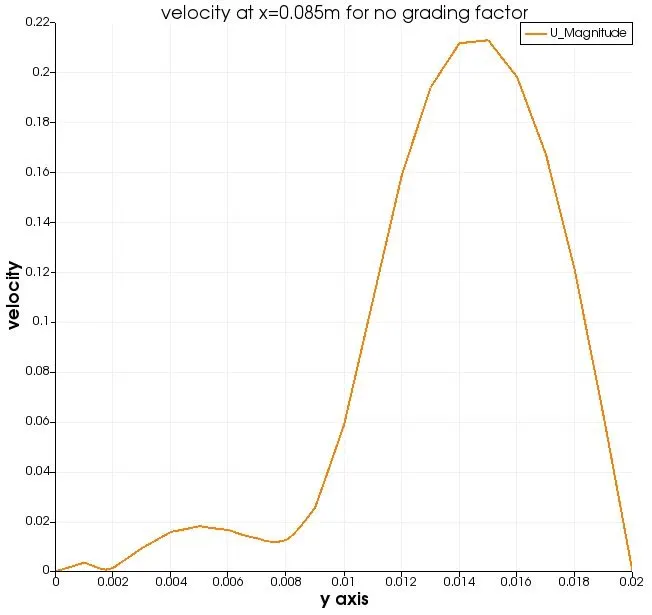
Above both the graph shows variation of velocity at section x=0.085m but in first case at the step region mesh is finner while in second graph mesh has same size all over the domain. Finner mesh is able to capture more accurate picture.From graph it can be seen that at the lower side where sudden increase in area has happened velocity is very low but at upper side of step because of innertia effect velocity is nearly same as of small channel velocity before step. At the upper and lower wall velocity is zero because application of no slip bounadary condition.If velocity is lowered and so as viscosity we may see flow reversal at the region of step.