Week 8 - Simulation of a backward facing step in OpenFOAM
OBJECTIVE :TO SIMULATE INCOMPRESSIBLE LAMINAR VISCOUS FLOW THROUGH A BACKWARD FACING STEP .ALSO TO OBSREVE VELOCITY AND PRESSURE CONTOURS VARIATION WITH RESPECT TO CHANGE IN THE GRADING FACTOR USING OPENFOAM
THEORY
The dynamic behaviour of the fluid flow is analyzed by conservation of mass ,energy and momentum.forces acting on fluid in motion can be evaluvated by Newton's 2nd law of motion F=ma
F =GRAVITY FORCE + PRESSUREFORCE + VISCOUS FORCE + TURBULENT FORCE + SURFACE TENSION FORCE + COMPRESSIBLITY FORCE
by necglecting viscous,turbulent,surfacetension and compressiblity force we arrive at following equation
F=GRAVITY FORCE + PRESSUREFORCE - EULER'S EQUATION OF MOTION
Differential form of Euler's eqution
X-Momentum Equation

Y-Momentum Equation

Z-Momentum Equation

Laplacian Equation
Phi represents the velocity potential funtion it is usefull for 3Dimensional flows ,if we know the potentional function we can evaluvate the corresponding velocitys in x,y and z directions.if the laplace equation is satisfied then the flow is said to irrotaional flow
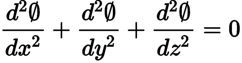
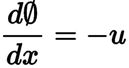
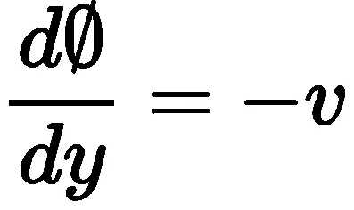
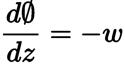
In the fvschemes file the above equtions are solved with Gauss linear finite volume method
PART 1
STEPS FOR SETTING UP THE SIMULATION WITHOUT GRADING FACTOR
step 1

step 2

step 3

step 4

step 5

step 6

BACKWARD FACING STEP GEOMETRY
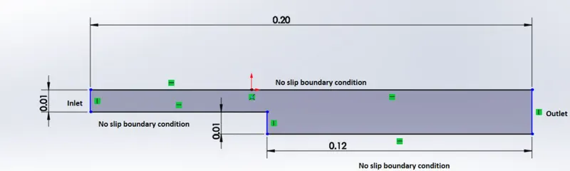
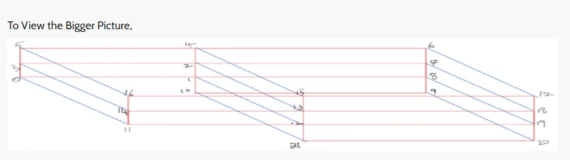
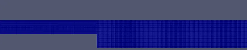
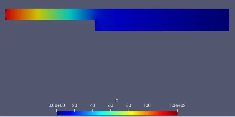
The above geometry is divided into five blocks as shown in the below figure and each vertex is assigned with a uniqe number,based on vertex number the vertex coordinates are arranged in the blockmeshdict file.
After that using right hand thumb rule the and vertex number are arranged to create individual blocks using hex command , grading is done by using simple grading commmand and number of grid points along x and y directions are also specified.
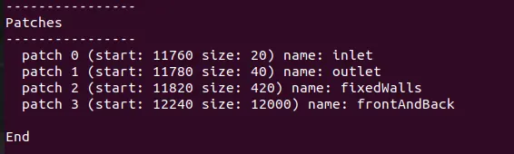
Boundarys like inlet ,outlet,fixedwall etc are specified using right hand thumb rule
BLOCKMESHDICT FILE
/*--------------------------------*- C++ -*----------------------------------*\
  =========                 |
  \\      /  F ield         | OpenFOAM: The Open Source CFD Toolbox
   \\    /   O peration     | Website:  https://openfoam.org
    \\  /    A nd           | Version:  9
     \\/     M anipulation  |
\*---------------------------------------------------------------------------*/
FoamFile
{
    format      ascii;
    class       dictionary;
    object      blockMeshDict;
}
// * * * * * * * * * * * * * * * * * * * * * * * * * * * * * * * * * * * * * //

convertToMeters 0.01;

vertices
(
    (0 0 0)
    (8 0 0)
    (8 0.5 0)
    (0 0.5 0)
    (8 1 0)
    (0 1 0)
    (20 1 0)
    (20 0.5 0)
    (20 0 0)
    (20 -1 0)
    (8 -1 0)
    (0 0 0.1)
    (8 0 0.1)
    (8 0.5 0.1)
    (0 0.5 0.1)
    (8 1 0.1)
    (0 1 0.1)
    (20 1 0.1)
    (20 0.5 0.1)
    (20 0 0.1)
    (20 -1 0.1)
    (8 -1 0.1)
);

blocks
(
    hex (0 1 2 3 11 12 13 14) (100 10 1) simpleGrading (1 1 1)
    hex (3 2 4 5 14 13 15 16) (100 10 1) simpleGrading (1 1 1)
    hex (2 7 6 4 13 18 17 15) (100 10 1) simpleGrading (1 1 1)
    hex (1 8 7 2 12 19 18 13) (100 10 1) simpleGrading (1 1 1)
    hex (10 9 8 1 21 20 19 12) (100 20 1) simpleGrading (1 1 1)
);

edges
(
);

boundary
(
    inlet
    {
        type wall;
        faces
        (
            (0 11 14 3)
            (3 14 16 5)
        );
    }
    outlet
    {
        type wall;
        faces
        (
            (9 8 19 20)
            (8 7 18 19)
            (7 6 17 18)
        );
    }
    fixedWalls
    {
        type wall;
        faces
        (
            (4 5 16 15)
            (0 1 12 11)
            (6 4 15 17)
            (10 9 20 21)
            (1 10 21 12)
        );
    }
    frontAndBack
    {
        type empty;
        faces
        (
            (11 12 13 14)
            (13 15 16 14)
            (13 18 17 15)
            (12 19 18 13)
            (21 20 19 12)
            (0 3 2 1)
            (3 5 4 2)
            (2 4 6 7)
            (1 2 7 8)
            (10 1 8 9)
        );
    }
);

mergePatchPairs
(
);

// ************************************************************************* //
step 7

step 8


MESH
step 9

In the controldict file change the end time and delta t value carefully so the courant number criteria is satisfied
courant number =(v*deltat)/deltax
CONTROLDICT FILE
/*--------------------------------*- C++ -*----------------------------------*\
  =========                 |
  \\      /  F ield         | OpenFOAM: The Open Source CFD Toolbox
   \\    /   O peration     | Website:  https://openfoam.org
    \\  /    A nd           | Version:  9
     \\/     M anipulation  |
\*---------------------------------------------------------------------------*/
FoamFile
{
    format      ascii;
    class       dictionary;
    location    "system";
    object      controlDict;
}
// * * * * * * * * * * * * * * * * * * * * * * * * * * * * * * * * * * * * * //

application     icoFoam;

startFrom       startTime;

startTime       0;

stopAt          endTime;

endTime         0.2;

deltaT          0.00001;

writeControl    timeStep;

writeInterval   20;

purgeWrite      0;

writeFormat     ascii;

writePrecision  6;

writeCompression off;

timeFormat      general;

timePrecision   6;

runTimeModifiable true;


// ************************************************************************* //
step 10


The inlet and fixed wall pressure boundary conditon is specified with neuman bc and outlet pressure conditon is specified with dirichilet bc
PRESSURE FILE
/*--------------------------------*- C++ -*----------------------------------*\
  =========                 |
  \\      /  F ield         | OpenFOAM: The Open Source CFD Toolbox
   \\    /   O peration     | Website:  https://openfoam.org
    \\  /    A nd           | Version:  9
     \\/     M anipulation  |
\*---------------------------------------------------------------------------*/
FoamFile
{
    format      ascii;
    class       volScalarField;
    object      p;
}
// * * * * * * * * * * * * * * * * * * * * * * * * * * * * * * * * * * * * * //

dimensions      [0 2 -2 0 0 0 0];

internalField   uniform 0;

boundaryField
{
    inlet
    {
        type            zeroGradient;
    }
    outlet
    {
        type            fixedValue;
        value           uniform 0;
    }

    fixedWalls
    {
        type            zeroGradient;
    }

    frontAndBack
    {
        type            empty;
    }
}

// ************************************************************************* // 
The inlet and fixed wall velocity boundary conditions are specified with dirichlet bc at inlet in x direction 1m/s is the velocity at fixed wall velocity is zero in all directions
VELOCITY FILE
/*--------------------------------*- C++ -*----------------------------------*\
  =========                 |
  \\      /  F ield         | OpenFOAM: The Open Source CFD Toolbox
   \\    /   O peration     | Website:  https://openfoam.org
    \\  /    A nd           | Version:  9
     \\/     M anipulation  |
\*---------------------------------------------------------------------------*/
FoamFile
{
    format      ascii;
    class       volVectorField;
    object      U;
}
// * * * * * * * * * * * * * * * * * * * * * * * * * * * * * * * * * * * * * //

dimensions      [0 1 -1 0 0 0 0];

internalField   uniform (0 0 0);

boundaryField
{
    inlet
    {
        type            fixedValue;
        value           uniform (1 0 0);
    }
    outlet
    {
        type            zeroGradient;
    }


    fixedWalls
    {
        type            noSlip;
        value           uniform (0 0 0);
    }

    frontAndBack
    {
        type            empty;
    }
}

// ************************************************************************* //
step 11


step 12
VELOCITY CONTOUR
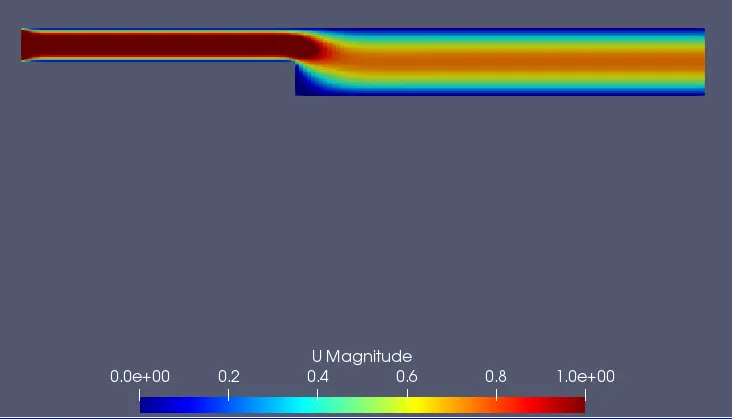
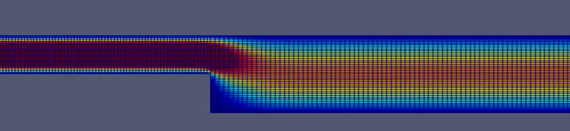
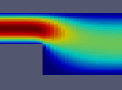
By observing the below velocity contour we can say that along length of the stepped block the main stream velocity have reduced and boundary layer thickness have increased
PRESSURE CONTOUR
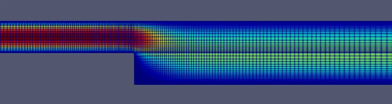
CLOSER VIEW OF VELOCITY CONTOUR AT STEP
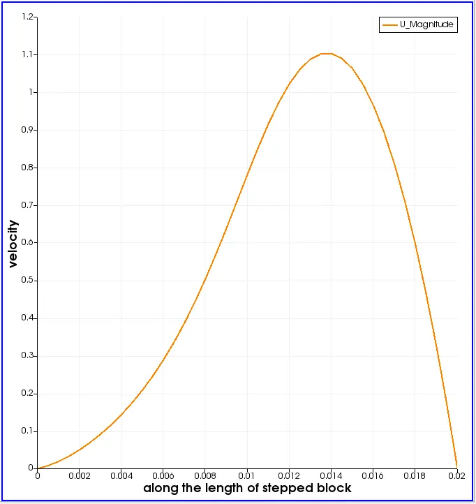
VELOCITY PROFILE AT 0.085 M FORM THE INLET OF THE STEPPED DUCT
By observing the below velocity profile we can say that peak velocity is at 0.014 meters from the inlet with magnitude of v=1.1 m/s.along flow direction at first the velocity increased but after 0.014 m the velocity off the mean stream decreased.
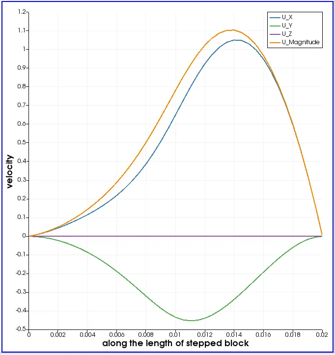
VELOCITY PROFILES IN X,Y AND Z DIRECTIONS AT 0.085 M FORM THE INLET OF THE STEPPED DUCT
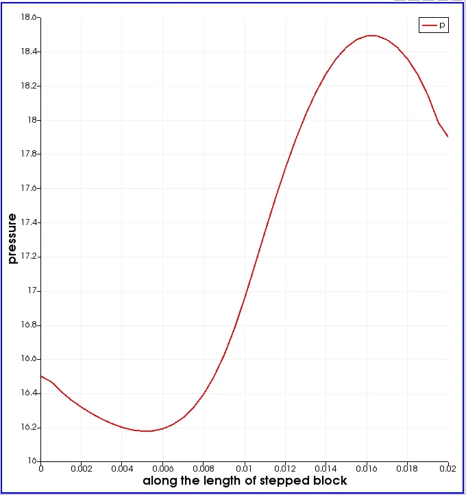
PRESSURE PROFILES AT 0.085 M FORM THE INLET OF THE STEPPED DUCT
The below graph represents the pressure profile along the length of the stepped duct.
PART 2
STEPS FOR SIMULATION OF BACKWARD FACING STEP WITH 0.2 GRADING FACTOR
step 1
the other steps in the simulation are same as that for previous simulation ,only change is in blocks section of the block mesh dict file the grading factor of 0.2 is used to strech the mesh on one side ,similar to the previous simulation the verteices are arranged with right hand thumb rule
grading factor =size of the end cell /size of the starting cell
the grading factor is used in such a way at the boundaries wall the mesh is fine else where coaresmesh is used.
    hex (0 1 2 3 11 12 13 14) (100 10 1) simpleGrading (0.2 5 1)
    hex (3 2 4 5 14 13 15 16) (100 10 1) simpleGrading (0.2 0.2 1)
    hex (2 7 6 4 13 18 17 15) (100 10 1) simpleGrading (5 0.2 1)
    hex (1 8 7 2 12 19 18 13) (100 10 1) simpleGrading (5 5 1)
    hex (10 9 8 1 21 20 19 12) (100 20 1) simpleGrading (5 5 1)
step 2
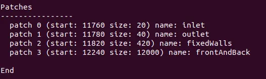
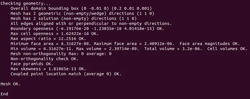
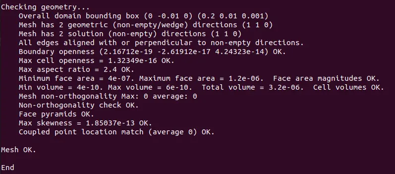
use the blockmesh command to create geometry and mesh the geometry with specified grading factor after that use check mesh command and type parafoam to see the virtual geometry in paraview
MESH WITH O.2 GRADING FACTOR

step 3

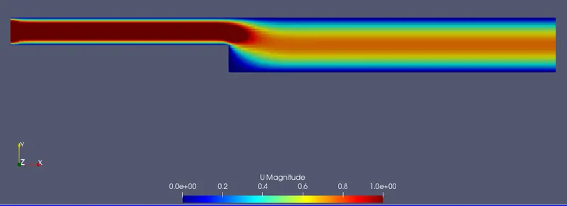
VELOCITY CONTOUR WITH O.2 GRADING FACTOR
PRESSURE CONTOUR WIHT O.2 GRADING FACTOR
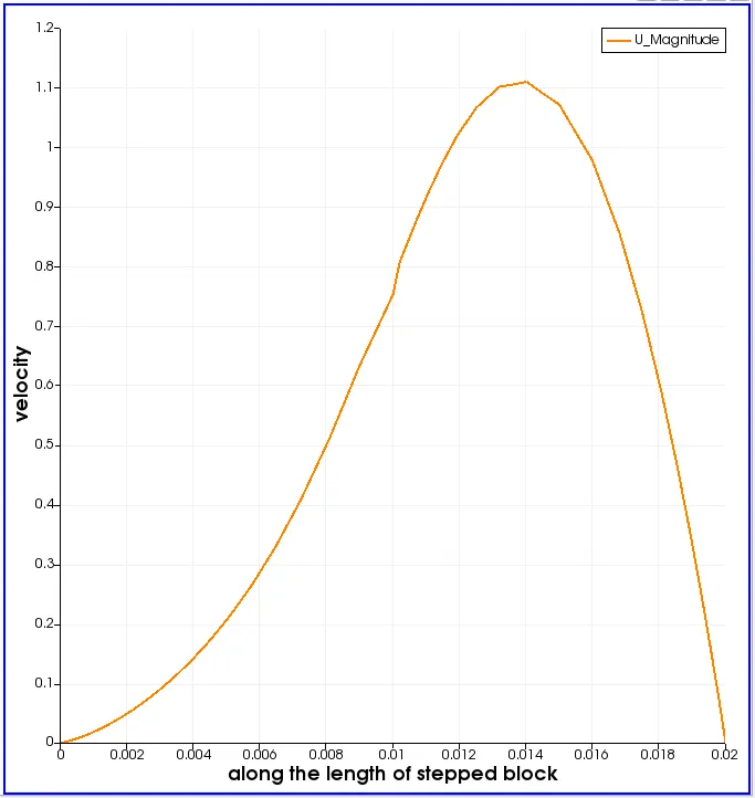
VELOCITY PROFILE AT 0.085 M FORM THE INLET OF THE STEPPED DUCT WITH 0.2 GRADING FACTOR
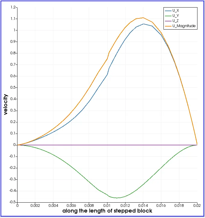
By observing the below velocity profile we can say that peak velocity is at 0.014 meters from the inlet with magnitude of v=1.1 m/s.along flow direction at first the velocity increased but after 0.014 m the velocity off the mean stream decreased.there is sudden jump in velocity in range of (0.008-0.012)
VELOCITY PROFILES IN X,Y AND Z DIRECTIONS AT 0.085 M FORM THE INLET OF THE STEPPED DUCT WITH 0.2 GRADING FACTOR
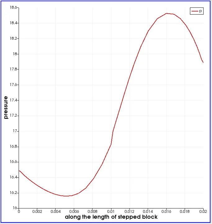
PRESSURE PROFILES AT 0.085 M FORM THE INLET OF THE STEPPED DUCT WITH 0.2 GRADING FACTOR
there is sudden jump in velocity in range of (0.008-0.012)
CONCLUSIONS
- The execution time with grading factor of 0.2 is more compaired to that of grading factor 1.
- There is no significant variation in velocity contour in both GF=0.2,GF =1(Grading factor) flow simulation.
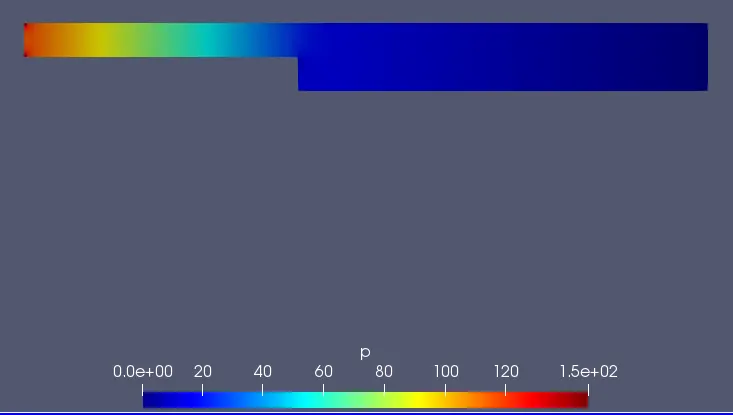
- There is singnificant change in pressure distribution in GF=0.2 simulation compaired to that of GF=1. the pressure distribution is uniform for GF=0.2 with max pressure of 9.6,where as in GF=1 pressure distribution is not uniform and it has max pressure of 11.6 at the inlet corners.
- the velocity profile of GF=0.2 is not smooth compaired to GF=1 velocity profile at 0.085m from the inlet this is because of the fine mesh near the stepped section fine in GF =0.2 compaired to that of GF=1.it concludes that with fine mesh we can captute the flow physics more detailed manner.