Week 8 - Simulation of a backward facing step in OpenFOAM
Aim:
To simulate a transient simulation of an incompressible-laminar-viscous flow through the backward facing step geometry.
Cases:
- Simulate the flow without using any grading factor (i.e., GF = 1)
- Simulate the flow with grading factor of 0.2. The cells should be finer near the walls (includig the step wall).
Desired output:
- Measure the velocity profile at 0.085 m from the inlet of the geometry for both case studies and compare. You can use the plot over line tool for this.
- Explain why Grading/Growth factor is essential for meshing.
Theory:
- The given flow is an incompressible laminar viscous flow where the incompressible refers to a flow in which the density remains constant in any fluid.whereas Laminar flow is a flow characterized by high momentum diffusion and low momentum convection. When a fluid is flowing through a closed channel such as a pipe or between two flat plates, either of two types of flow may occur depending on the velocity and viscosity of the fluid.
- The transient flow is the flow in which the velocity of a fluid particle changes with the time and the position.
- Viscous flow is a type of fluid flow in which there is a continuous steady motion of the particles; the motion at a fixed point always remains constant.
Mesh Specification: Number of Blocks = 5
- Number of cells along the x direction (longer dimension) = 200
- Number of cells along the longer y direction = 20
Procedure:
- It is given that the simulation is transient incompressible-laminar-viscous flow so, we go for a similar option in the tutorials based on the physics of the flow.
- First of all, we have to open the terminal in the Ubuntu Linux OS by pressing the shortcut key 'Ctrl+Alt+T'
- Type 'tut' to open tutorial, type ls to see the list of folders inside the tutorials.
- Select 'incompressible' from the list of folders because our problem is incompressible flow.
- Select 'icoFoam' from the incompressible folder. The solver we have to choose is "icoFoam" solver which is the tutorial of the transient incompressible , laminar flow of Newtonian fluids.
- Then we choose 'cavity', which is matching over problem by the command 'cd cavity'
- Inside cavity folder , we can see the folders 'cavity, cavityclipped,cavityGrade'
- To Copy the cavity tutorial folder and paste it in the 'Foam run' by the command 'cp -r cavity/ $FOAM_RUN '
- In run Open the cavity folder in which we have copied by 'ls'
- 'cd cavity' we can see that 3 folders that is being presented '0, constant, system' where '0' contains the initial condition that is pressure and velocity where 'constant' consists of polymesh and transport properties and then 'system' consists of ' blockmeshDict, controldict, fvschemes, fvSolution' which controls numerical schemes and solution procedures.
- 'cd system/ ' to go into the system folder.
- 'gedit blockMeshdict' to edit the file according to our geometry
- 'gedit controlDict' to edit the end time and time steps dt.
- The fvSchemes and fvSolution files are the finite volume based schemes and solutions to solve our problem.There is no need to change the solver files.
- 'cd constant'==>'gedit transportProperties' to edit the transportproperties file in the constant folder by giving Kinematic viscosity of (working fluid) air i.e..,1.48e-5 m^2/s
- In '0' folder , we have to edit the initial and boundary conditions of pressure and velocity .In 'gedit p' , the inlet pressure is floating ,the outlet as a fixed value , front and back does not affect the flow because of no slip boundary conditions and fixed walls as well floating.
- 'gedit U' give the inital velocity as 1 m/s
- After changing all the parametrs in the tutorial file according to our problem, use 'blockMesh' command to create the mesh and check the mesh using 'checkMesh' and if it shows 'Mesh ok' our mesh is correct, we can proceed to the next step.
- Now we can run the simulation using the 'icoFoam' solver
- After the simulation is done, type 'paraFoam' command which will take us to the paraview ( postprocessor) where we can see the simulation in graphics, final results and plot the graphs.
Geometry creation and Mesh setup:
Splitting the geometry into 5 blocks, we get
Now let’s, start indexing the Vertices on the Back side of the Blocks, Since openFoam uses C++ programming, we start the index from “0”. (The Numbering of the vertices can be varied according to your comfort)
Similarly, the indexing for the frontside of the Blocks are,
To View the Bigger Picture,
Finally, to define the blocks, we need to specify the right order of vertex indices.
Case 1 - Simulate the flow without using any grading factor (i.e., GF = 1)
BlockMeshDict code:
/*--------------------------------*- C++ -*----------------------------------*
  =========                 |
  \      /  F ield         | OpenFOAM: The Open Source CFD Toolbox
   \    /   O peration     | Website:  https://openfoam.org
    \  /    A nd           | Version:  8
     \/     M anipulation  |
*---------------------------------------------------------------------------*/
FoamFile
{
    version     2.0;
    format      ascii;
    class       dictionary;
    object      blockMeshDict;
}
// * * * * * * * * * * * * * * * * * * * * * * * * * * * * * * * * * * * * * //

convertToMeters 1;

vertices
(
    (0 0 0)              //00
    (0.08 0 0)           //01
    (0.08 0.005 0)       //02
    (0 0.005 0)          //03
    (0.08 0.01 0)        //04
    (0 0.01 0)           //05
    (0.2 0.01 0)         //06
    (0.2 0.005 0)        //07
    (0.2 0 0)            //08
    (0.2 -0.01 0)        //09
    (0.08 -0.01 0)       //10
    (0 0 0.01)           //11
    (0.08 0 0.01)        //12
    (0.08 0.005 0.01)    //13
    (0 0.005 0.01)       //14
    (0.08 0.01 0.01)     //15
    (0 0.01 0.01)        //16
    (0.2 0.01 0.01)      //17
    (0.2 0.005 0.01)     //18
    (0.2 0 0.01)         //19
    (0.2 -0.01 0.01)     //20
    (0.08 -0.01 0.01)    //21
);

blocks
(
    hex (0 1 2 3 11 12 13 14) (80 10 1) simpleGrading (1 1 1)    //block1
    hex (3 2 4 5 14 13 15 16) (80 10 1) simpleGrading (1 1 1)    //block2
    hex (2 7 6 4 13 18 17 15) (120 10 1) simpleGrading (1 1 1)   //block3
    hex (1 8 7 2 12 19 18 13) (120 10 1) simpleGrading (1 1 1)   //block4
    hex (10 9 8 1 21 20 19 12) (120 20 1) simpleGrading (1 1 1)  //block5
);

edges
(
);

boundary
(
    inlet
    {
        type patch;
        faces
        (
            (0 11 14 3)
            (3 14 16 5)
        );
    }
    outlet
    {
        type patch;
        faces
        (
            (19 20 9 8)
            (18 19 8 7)
            (17 18 7 6)
        );
     }
     frontAndBack
     {
        type empty;
        faces
        (
            (11 12 13 14)
            (14 13 15 16)
            (21 20 19 12)
            (12 19 18 13)
            (13 18 17 15)
            (0 1 2 3)
            (3 2 4 5)
            (10 9 8 1)
            (1 8 7 2)
            (2 7 6 4)
         );
       }
    fixedWalls
    {
        type wall;
        faces
        (
            (16 15 4 5)
            (15 17 6 4)
            (11 12 1 0)
            (21 20 9 10)
            (10 21 12 1)
        );
    }

);

mergePatchPairs
(
);

// ************************************************************************* //
Case 2 - Simulate the flow with grading factor of 0.2. The cells should be finer near the walls (includig the step wall).
BlockMeshDict code:
/*--------------------------------*- C++ -*----------------------------------*
  =========                 |
  \      /  F ield         | OpenFOAM: The Open Source CFD Toolbox
   \    /   O peration     | Website:  https://openfoam.org
    \  /    A nd           | Version:  8
     \/     M anipulation  |
*---------------------------------------------------------------------------*/
FoamFile
{
    version     2.0;
    format      ascii;
    class       dictionary;
    object      blockMeshDict;
}
// * * * * * * * * * * * * * * * * * * * * * * * * * * * * * * * * * * * * * //

convertToMeters 1;

vertices
(
    (0 0 0)              //00
    (0.08 0 0)           //01
    (0.08 0.005 0)       //02
    (0 0.005 0)          //03
    (0.08 0.01 0)        //04
    (0 0.01 0)           //05
    (0.2 0.01 0)         //06
    (0.2 0.005 0)        //07
    (0.2 0 0)            //08
    (0.2 -0.01 0)        //09
    (0.08 -0.01 0)       //10
    (0 0 0.01)           //11
    (0.08 0 0.01)        //12
    (0.08 0.005 0.01)    //13
    (0 0.005 0.01)       //14
    (0.08 0.01 0.01)     //15
    (0 0.01 0.01)        //16
    (0.2 0.01 0.01)      //17
    (0.2 0.005 0.01)     //18
    (0.2 0 0.01)         //19
    (0.2 -0.01 0.01)     //20
    (0.08 -0.01 0.01)    //21
);

blocks
(
    hex (0 1 2 3 11 12 13 14) (80 10 1) simpleGrading (0.2 5 1)    //block1
    hex (3 2 4 5 14 13 15 16) (80 10 1) simpleGrading (0.2 0.2 1)    //block2
    hex (2 7 6 4 13 18 17 15) (120 10 1) simpleGrading (5 0.2 1)   //block3
    hex (1 8 7 2 12 19 18 13) (120 10 1) simpleGrading (5 5 1)   //block4
    hex (10 9 8 1 21 20 19 12) (120 20 1) simpleGrading (5 5 1)  //block5
);

edges
(
);

boundary
(
    inlet
    {
        type patch;
        faces
        (
            (0 11 14 3)
            (3 14 16 5)
        );
    }
    outlet
    {
        type patch;
        faces
        (
            (19 20 9 8)
            (18 19 8 7)
            (17 18 7 6)
        );
     }
     frontAndBack
     {
        type empty;
        faces
        (
            (11 12 13 14)
            (14 13 15 16)
            (21 20 19 12)
            (12 19 18 13)
            (13 18 17 15)
            (0 1 2 3)
            (3 2 4 5)
            (10 9 8 1)
            (1 8 7 2)
            (2 7 6 4)
         );
       }
    fixedWalls
    {
        type wall;
        faces
        (
            (16 15 4 5)
            (15 17 6 4)
            (11 12 1 0)
            (21 20 9 10)
            (10 21 12 1)
        );
    }

);

mergePatchPairs
(

);

// ************************************************************************* //
1. Here, we have inputed the vertices for the creation of the geometry.
2. In Hex , we give the faces of front and back to form or merge each blocks and we give the number of cells in the x, y and z direction. In simpleGrading , the grading factors were given based on the cases.
3. We give the faces for inlet, outlet, front and back and fixed walls in the boundaries.
controlDict code:
- Simulation run time t = 50s
- Time step dt = 0.0005s
/*--------------------------------*- C++ -*----------------------------------*
  =========                 |
  \      /  F ield         | OpenFOAM: The Open Source CFD Toolbox
   \    /   O peration     | Website:  https://openfoam.org
    \  /    A nd           | Version:  8
     \/     M anipulation  |
*---------------------------------------------------------------------------*/
FoamFile
{
    version     2.0;
    format      ascii;
    class       dictionary;
    location    "system";
    object      controlDict;
}
// * * * * * * * * * * * * * * * * * * * * * * * * * * * * * * * * * * * * * //

application     icoFoam;

startFrom       startTime;

startTime       0;

stopAt          endTime;

endTime         0.5;

deltaT          0.0005;

writeControl    timeStep;

writeInterval   20;

purgeWrite      0;

writeFormat     ascii;

writePrecision  6;

writeCompression off;

timeFormat      general;

timePrecision   6;

runTimeModifiable true;


// ************************************************************************* //
fvSchemes code:
/*--------------------------------*- C++ -*----------------------------------*
  =========                 |
  \      /  F ield         | OpenFOAM: The Open Source CFD Toolbox
   \    /   O peration     | Website:  https://openfoam.org
    \  /    A nd           | Version:  8
     \/     M anipulation  |
*---------------------------------------------------------------------------*/
FoamFile
{
    version     2.0;
    format      ascii;
    class       dictionary;
    location    "system";
    object      fvSchemes;
}
// * * * * * * * * * * * * * * * * * * * * * * * * * * * * * * * * * * * * * //

ddtSchemes
{
    default         Euler;
}

gradSchemes
{
    default         Gauss linear;
    grad(p)         Gauss linear;
}

divSchemes
{
    default         none;
    div(phi,U)      Gauss linear;
}

laplacianSchemes
{
    default         Gauss linear orthogonal;
}

interpolationSchemes
{
    default         linear;
}

snGradSchemes
{
    default         orthogonal;
}


// ************************************************************************* //
fvSolution code:
/*--------------------------------*- C++ -*----------------------------------*
  =========                 |
  \      /  F ield         | OpenFOAM: The Open Source CFD Toolbox
   \    /   O peration     | Website:  https://openfoam.org
    \  /    A nd           | Version:  8
     \/     M anipulation  |
*---------------------------------------------------------------------------*/
FoamFile
{
    version     2.0;
    format      ascii;
    class       dictionary;
    location    "system";
    object      fvSolution;
}
// * * * * * * * * * * * * * * * * * * * * * * * * * * * * * * * * * * * * * //

solvers
{
    p
    {
        solver          PCG;
        preconditioner  DIC;
        tolerance       1e-06;
        relTol          0.05;
    }

    pFinal
    {
        $p;
        relTol          0;
    }

    U
    {
        solver          smoothSolver;
        smoother        symGaussSeidel;
        tolerance       1e-05;
        relTol          0;
    }
}

PISO
{
    nCorrectors     2;
    nNonOrthogonalCorrectors 0;
    pRefCell        0;
    pRefValue       0;
}


// ************************************************************************* //
Initial and Boundary conditions:
Pressure File
/*--------------------------------*- C++ -*----------------------------------*
  =========                 |
  \      /  F ield         | OpenFOAM: The Open Source CFD Toolbox
   \    /   O peration     | Website:  https://openfoam.org
    \  /    A nd           | Version:  8
     \/     M anipulation  |
*---------------------------------------------------------------------------*/
FoamFile
{
    version     2.0;
    format      ascii;
    class       volScalarField;
    object      p;
}
// * * * * * * * * * * * * * * * * * * * * * * * * * * * * * * * * * * * * * //

dimensions      [0 2 -2 0 0 0 0];               //dimensions [kg m sec K mol A cd ]Here pressure is represented as p/rho in dimensional quantity

internalField   uniform 0;

boundaryField
{
    inlet
    {
        type            zeroGradient;            // The inlet pressure is floating
    }

    outlet
    {
        type            fixedValue;             // making the outlet pressure as a fixed value
        value           uniform 0;
    }

    frontAndBack
    {
        type            empty;                  // Here the front and back does not affect the flow so, the pressure is empty
    }

    fixedWalls
    {
        type            zeroGradient;           // Here also the pressure at the fixed walls are floating
    }
}

// ************************************************************************* //
Velocity File
/*--------------------------------*- C++ -*----------------------------------*
  =========                 |
  \      /  F ield         | OpenFOAM: The Open Source CFD Toolbox
   \    /   O peration     | Website:  https://openfoam.org
    \  /    A nd           | Version:  8
     \/     M anipulation  |
*---------------------------------------------------------------------------*/
FoamFile
{
    version     2.0;
    format      ascii;
    class       volVectorField;
    object      U;
}
// * * * * * * * * * * * * * * * * * * * * * * * * * * * * * * * * * * * * * //

dimensions      [0 1 -1 0 0 0 0];         //Here the unit is m/s [M^0 L^1 T^-1]

internalField   uniform (0 0 0);

boundaryField
{
    inlet
    {
        type            fixedValue;
        value           uniform (1 0 0);  // velocity is fixed at inlet
    }

    outlet
    {
        type            zeroGradient;     // velocity is floating at outlet
    }

    frontAndBack
    {
        type            empty;            // velocity is empty because of no changes due to that faces to the flow
    }

    fixedWalls
    {
        type            noSlip;           // velocity is zero at the fixed walls
    }


}

// ************************************************************************* //
transportProperties code:
Kinematic Viscosity (nu) of the fluid medium i.e..Air at 20 degree celsius= 1.48e-5 m^2/s
/*--------------------------------*- C++ -*----------------------------------*
  =========                 |
  \      /  F ield         | OpenFOAM: The Open Source CFD Toolbox
   \    /   O peration     | Website:  https://openfoam.org
    \  /    A nd           | Version:  8
     \/     M anipulation  |
*---------------------------------------------------------------------------*/
FoamFile
{
    version     2.0;
    format      ascii;
    class       dictionary;
    location    "constant";
    object      transportProperties;
}
// * * * * * * * * * * * * * * * * * * * * * * * * * * * * * * * * * * * * * //

nu              [0 2 -1 0 0 0 0] 1.48e-5;


// ************************************************************************* //
Results:
Case 1
Mesh:-
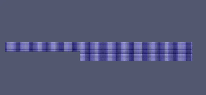
Here, we have used the default grading factor as the result , the mesh is finer and even throughout the geometry.
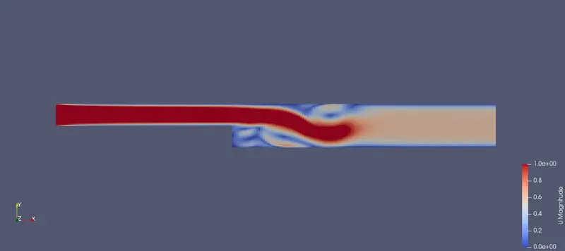
Velocity flow through the backward facing step geometry:-
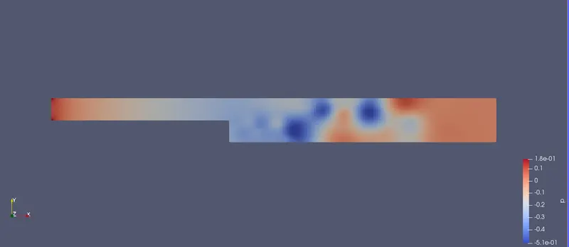
Flow Pressure :-
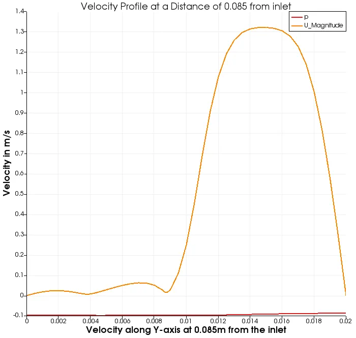
Velocity profile at a Distance of 0.085m from the inlet:-
Animation link for the velocity flow: https://youtu.be/GYnU5PSimlI
case 2
Mesh:-
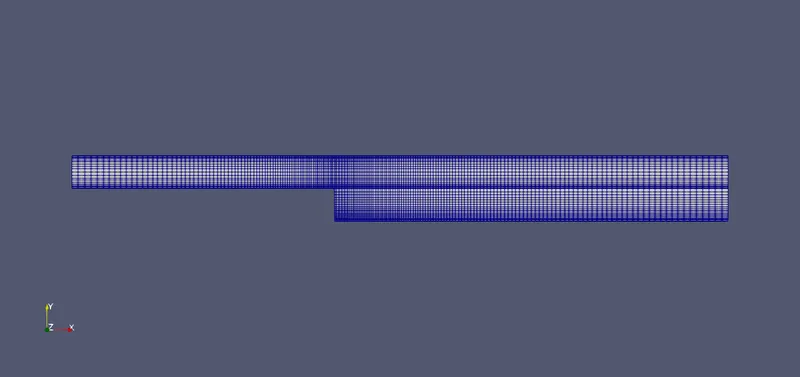
Here, we have created the finer mesh close to the wall and with the grading factor 0.2
Velocity flow through the backward facing step geometry:-
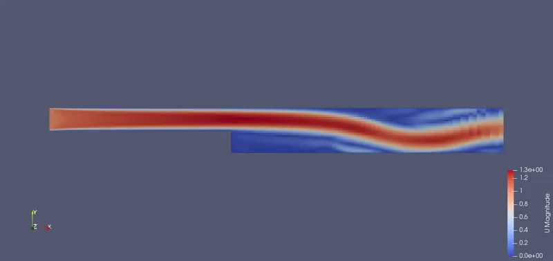
Flow Pressure:-
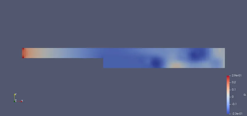
Velocity profile at a Distance of 0.085m from the inlet:-
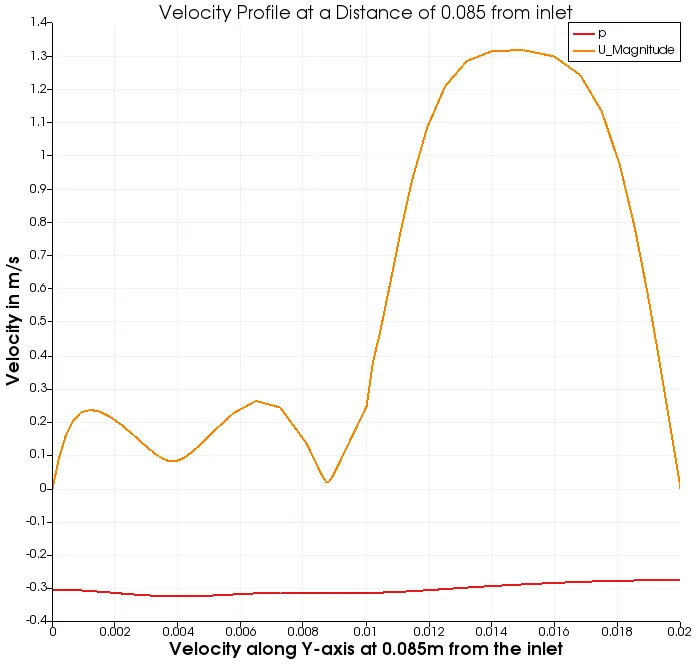
Animation link for the velocity flow: https://youtu.be/PPntQd9puKs
Why Grading/Growth factor is essential for meshing:-
- Grading factor helps us to adjust the size of the cell at the starting as well as the end of the blocks.
- Grading factor = (size of the end cell)/(size of the starting cell)
- It helps us to make the mesh finer and coarser wherever we need to make it and finer mesh gives us accurate solutions than the coarser mesh. The coarse mesh gives us results with some liberations which are not much accurate.
- In simple words, simpleGrading stretches cushes the mesh where required. The simple description specifies uniform expansions in the local x, y and z directions respectively with only 3 expansion ratios simpleGrading (x,y,z).
- As we decrease the grading ratio we will get the smooth results at the backward-facing step.
Conclusion:-
- We know that the velocity of the flow increases from inlet to outlet because of the increase in area, as the area of the profile increases , the velocity decreases.
- In the first case, the simpleGrading factor is default as one where the mesh is finer and even throughout the geometry. So, the velocity profile shows us the normal curve at 0.085m from the inlet.
- Whereas, In the second case the grading factor is 0.2 and the mesh is finer near the walls and coarser in the centre of the profile. So, the velocity profile shown was the smooth curves which has the slight bends in the middle because of the coarser area and also the velocity curve gives us more accurate results.
- From this, we can conclude that the finer meshes gives us more accurate results.