Week 8 - Simulating Cyclone separator with Discrete Phase Modelling
AIM: to simulate the flow through a cyclone separator and showing the results for the different particle sizes and the different velocities.
we have to simulate the six cases
1).set the velocity constant to 3 m/s and do simulation for the varying size of the particle.
2).set the particle size to constant and simulate for the different velocities.
models of the cyclone separator:
Cyclone Separator :
Cyclone separators or simply cyclones are separation devices (dry scrubbers) that use the principle of inertia to remove particulate matter from flue gases. Cyclone separators are one of many air pollution removers known as pre-cleaners since they generally remove larger pieces of particulate matter.
This prevents finer filtration methods from having to deal with large, more abrasive particles later on. In addition, several cyclone separators can operate in parallel, and this system is known as a multi-cyclone.
It is important to note that cyclones can vary drastically in their size. The size of the cyclone depends largely on how much flue gas must be filtered, thus larger operations tend to need larger cyclones. For example, several different models of one cyclone type can exist, and the sizes can range from a relatively small 1.2-1.5 meters tall (about 4-5 feet) to around 9 meters (30 feet)—which is about as tall as a three-story building.
Working:
Cyclone separators work much like a centrifuge, but with a continuous feed of dirty air. In a cyclone separator, dirty flue gas is fed into a chamber. The inside of the chamber creates a spiral vortex, similar to a tornado. This spiral formation and the separation are shown in the Figure below. The lighter components of this gas have less inertia, so it is easier for them to be influenced by the vortex and travel up it. Contrarily, larger components of particulate matter have more inertia and are not as easily influenced by the vortex.
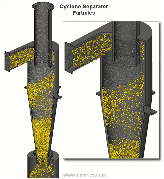
Most cyclones are built to control and remove particulate matter that is larger than 10 micrometers in diameter. However, there do exist high-efficiency cyclones that are designed to be effective on particles as small as 2.5 micrometers. As well, these separators are not effective on extremely large particulate matter. For particulates around 200 micrometers in size, gravity settling chambers or momentum separators are a better option.
Out of all of the particulate-control devices, cyclone separators are among the least expensive. They are often used as a pre-treatment before the flue gas enters more effective pollution control devices. Therefore, cyclone separators can be seen as "rough separators" before the flue gas reaches the fine filtration stages.
geometry preparation:
Geometry:
Fluid Volume extracted using SpaceClaim is shown below:
Mesh Details:
Boundary Conditions:
- Inlet & outlets are as shown above.
- Gravity is enabled in the -ve y-direction.
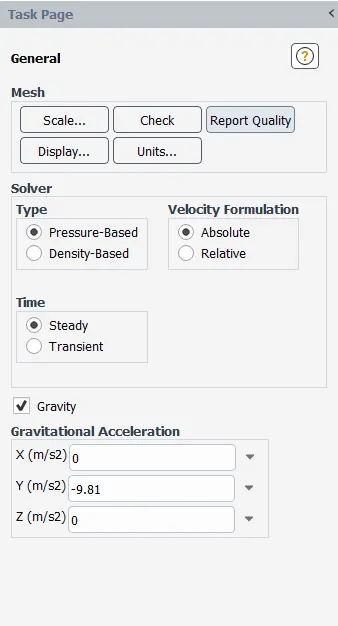
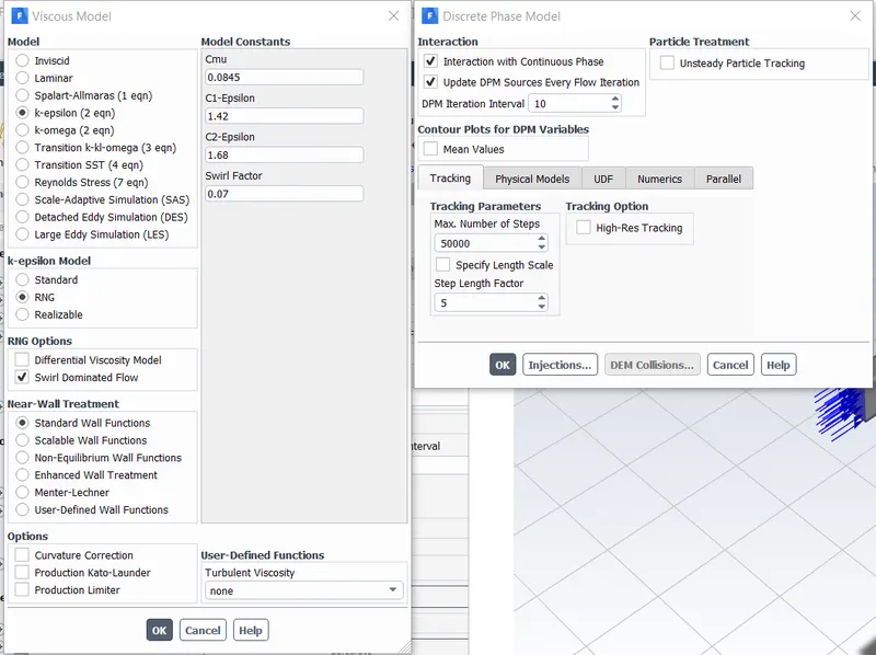
- The swirl-dominated RNG K-epsilon model is used here to capture the flow more accurately.
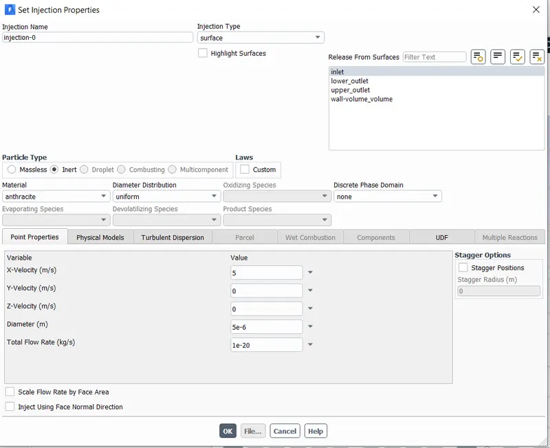
- The Discrete phase modeling is used to track the flow of the particles.
- No of step for particle tracking = 50000
- Injection Material : Anthracite (5microns in diameter)
- Velocity Inlet: 3m/s
- Outlet: Pressure Outlet( Gauge Pressure= 0Pa)
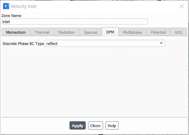
- DPM Settings are varied b/w reflect, escape, trap & wall jet.
Reflect: The particle rebounds off the boundary in question with a change in its momentum as defined by the coefficient of restitution.
Escape: Particle escapes out when encountered by the boundary.
Trap: The trajectory calculation is terminated & the fate of the particle is recorded as a trap.
Wall-Jet: The wall-jet type boundary condition is applicable for high-temperature walls where no significant liquid film is found & high Weber No impacts when the spray acts as a jet. This model does not apply to regimes where the film is important.
solution approach and solver requirement:
RESULTS
case(1):
- in this case, we are making the velocity constant and we are visualizing the difference in results for different particle size
Results for the particle size of 1 micron with a velocity of 3m/s:
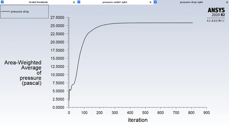
pressure at inlet:
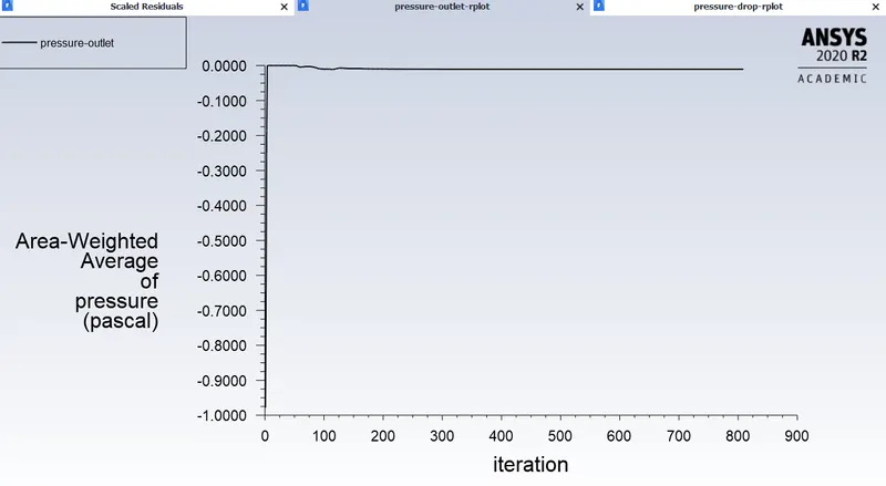
pressure at outlet:
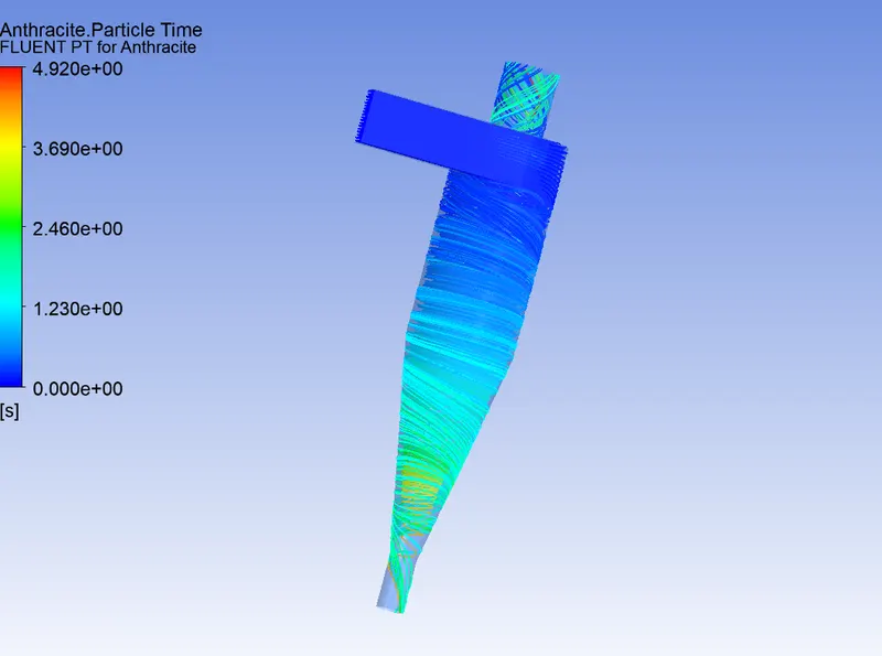
Particle Tracking:
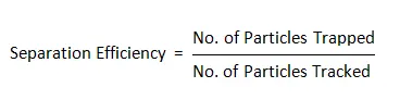
Separation Efficiency in % = (52 / 98) * 100
Separation Efficiency = 53.06 %
Results for the particle size of 2 microns with a velocity of 3m/s:
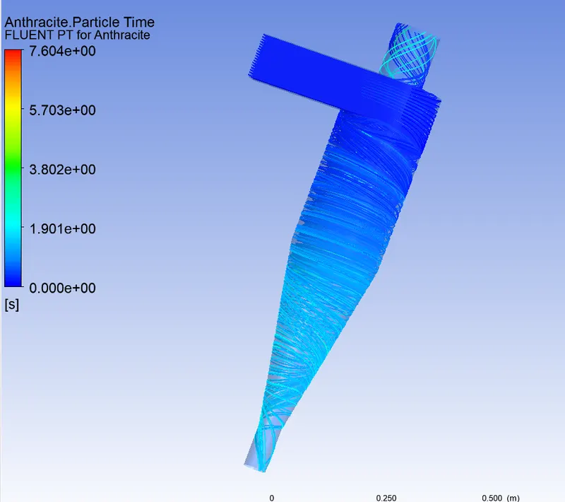
pressure at inlet:
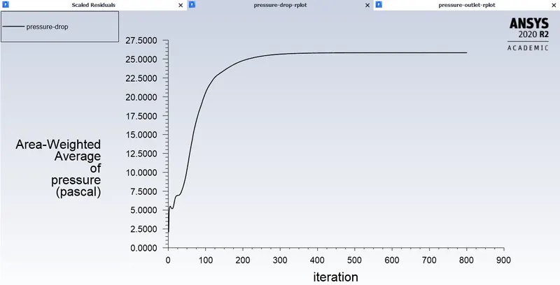
pressure at outlet:
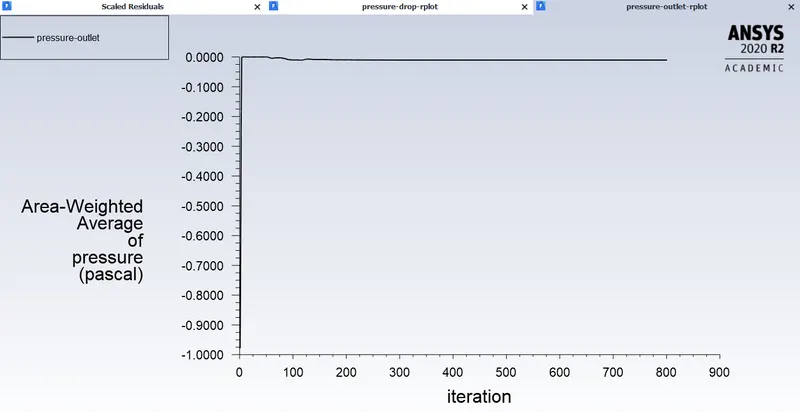
Particle Tracking:
Separation Efficiency in % = (75 / 98) * 100
Separation Efficiency = 76.53 %
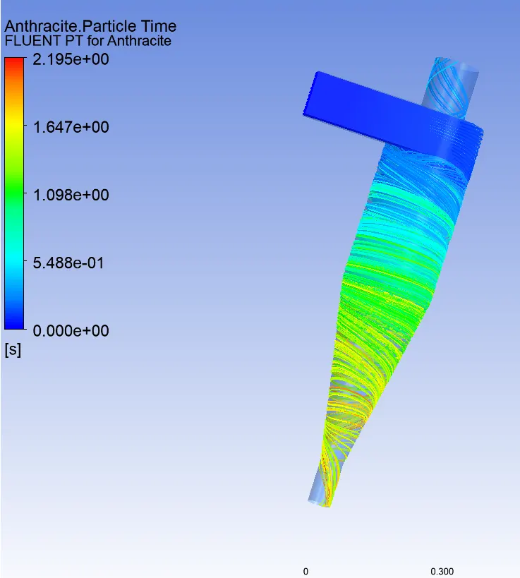
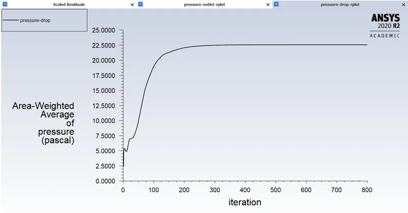
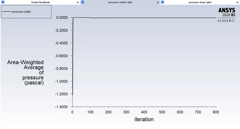
Results for the particle size of 5 microns with a velocity of 3m/s:
pressure at inlet:
pressure at outlet:
Particle Tracking:
Separation Efficiency in % = (98 / 98) * 100
Separation Efficiency = 100 %
case(2)
Results for the varying velocity and keeping the particle size constant i.e 5 micron
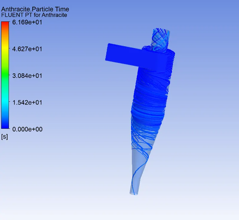
Inlet velocity of the particle and the discrete phase is the same i.e 1m/s:
pressure at inlet:
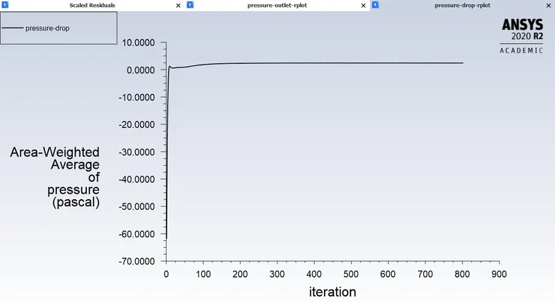
pressure at outlet:
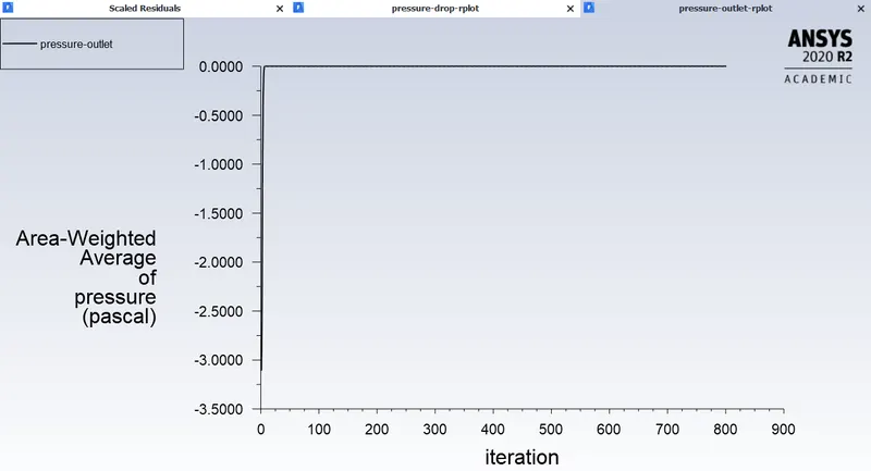
Particle Tracking:
Separation Efficiency in % = (7 / 98) * 100
Separation Efficiency = 7.14 %
Inlet velocity of the particle and the discrete phase is the same i.e 3m/s:
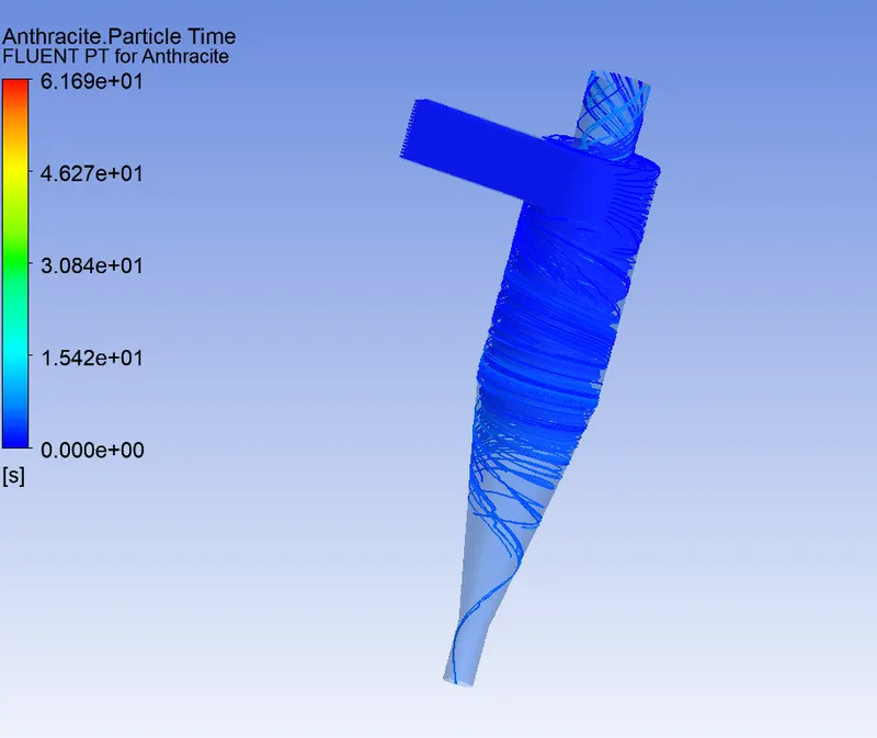
pressure at inlet:
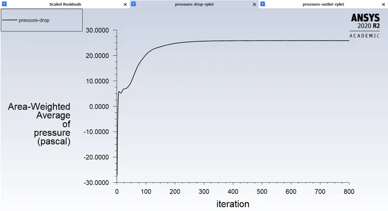
pressure at outlet:
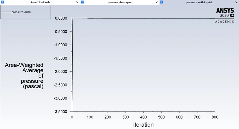
Particle Tracking:
Separation Efficiency in % = (98 / 98) * 100
Separation Efficiency = 100 %
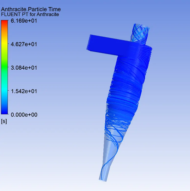
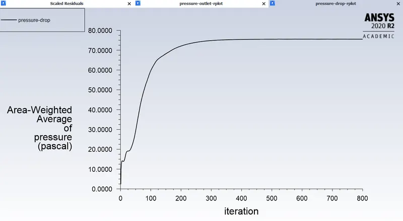
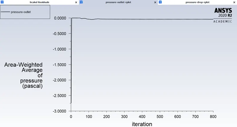
Inlet velocity of the particle and the discrete phase is the same i.e 5m/s:
pressure at inlet:
pressure at outlet:
Particle Tracking:
Separation Efficiency in % = (98 / 98) * 100
Separation Efficiency = 100 %