Week 8 - Simulating Cyclone separator with Discrete Phase Modelling
Cyclone separator challenge
Aim: Simulating cyclone separator with discrete phase modelling
Introduction: Cyclone separator is a device which utilizes rotatory motion and separates the particles present in the mixture. It is used in various industries where two different particles need to be separated. For example, in power plants, air gets mixed with coal particles, to make the air clean it is passed through cyclone separator. Coal particles get trapped and clean air is released in environment. It is also used in spray modelling, IC engine fuel injection etc.
Theory: The particles with heavier mass gets separated due to centrifugal force which acts tangentially from the centre. As the force is directly proportional to mass and velocity, it means more the mass or velocity, higher force will act on particles making easier to separate from mixture.
Solving and modelling approach: In this problem, discrete phase modelling has been used. The particles are tracked through continuous phase modelling. Diameter and velocity of particles are provided. Inert particles are used in modelling.
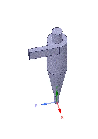
Geometry: Geometry was imported and fluid volume was extracted.
Meshing:
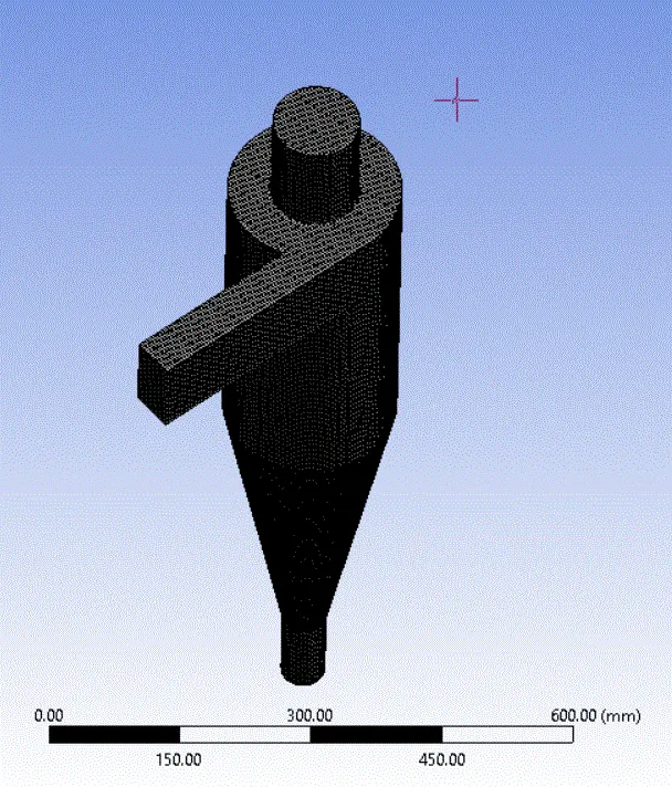
A fine mesh of 5 mm element size was provided.
Body fitted cartesian mesh was used.
Setup:
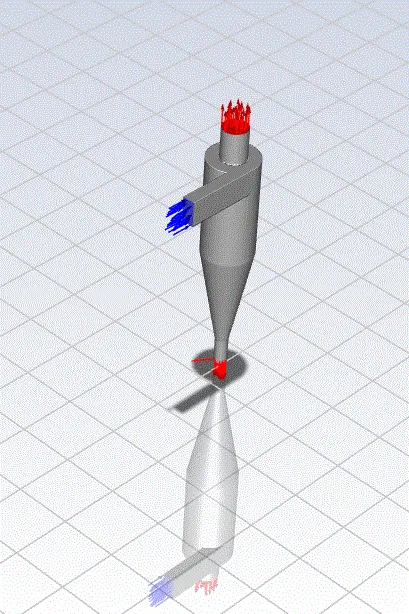
k-epsilon model with RNG and swirl dominated flow was used.
Discrete phase modelling was enabled with injections with inert particles.
Boundary conditions was provided with second order upwind scheme.
Results:
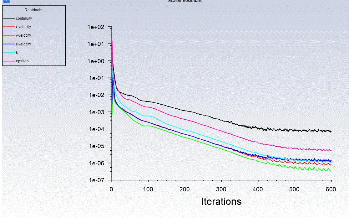
Results were computed from 600 iterations as residues was found stable.
Case 1: D = 1 μm, velocity = 3 m/s
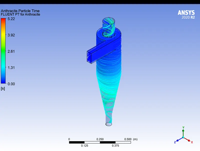
Efficiency = particles trapped/ particles tracked
Efficiency = 143/378 = 37.8%
Case 2: D = 5 μm, velocity = 3 m/s
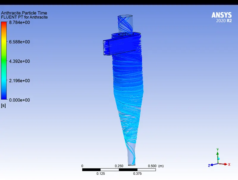
Efficiency = particles trapped/ particles tracked
Efficiency = 260/378 = 37.8% = 68.7%
Case 3: D = 5 μm, velocity = 1 m/s
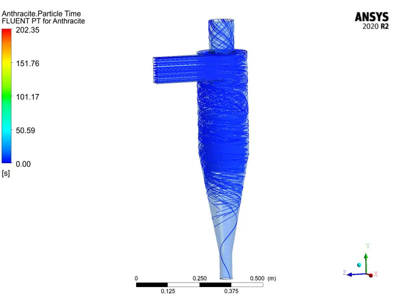
Efficiency = particles trapped/ particles tracked
Efficiency = 10/378 = 37.8% = 2.64%
Pressure difference from inlet to outlet = 2.48 Pa.
Case 4: D = 5 μm, velocity = 5 m/s
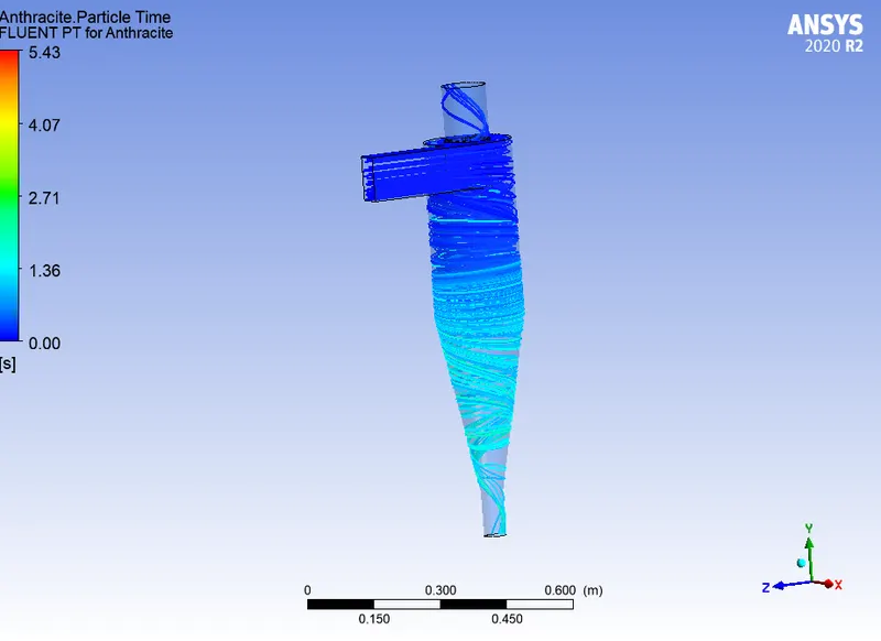
Efficiency = particles trapped/ particles tracked
Efficiency = 236/378 = 62.4%
Pressure difference from inlet to outlet = 82.45 Pa.
Conclusions:
- As the particle size was increased, the efficiency was increased.
- Similarly, as the velocity was increased, efficiency also increased.
- Also, as the velocity increases from 1m/s to 5 m/s, pressure drop increases i.e., from 2.48 Pa to 82.45 Pa respectively.
Gaps: Effect of geometry on efficiency can also be included in the challenge.
Four empirical models for calculating separator efficiency
Standard K-epsilon model – it involves solution of kinetic energy of turbulence at computational cell. They are not optimized for swirling flows found in cyclones. But it is simple, requires less computation and results deviate 12% from experimental results.
RNG K-Epsilon underestimates the axial velocity profile across radial direction and overestimates the magnitude of tangential velocity.
Reynold stress model – It calculates transport equations for each Reynolds stress components and for dissipation transport. Thus, results are more accurate for swirl flow pattern, axial velocity, pressure drop etc. on cyclone simulations.
Algebraic stress model – cannot predict the recirculation zone and vortex in swirling flow.
video link :