Week 8 - Simulating Cyclone separator with Discrete Phase Modelling
Aim:- To perform analysis on cyclone separator and calculate the separation efficiency and pressure drop.
Objective:-
- To write a few words about any four empirical models used to calculate the cyclone separator efficiency.
- To perform an analysis on a given cyclone separator model by varying the particle diameter from 1 μm to 5 μm and calculate the separation efficiency in each case. Discuss the results. [Use both the velocity's as 3m/sec.]
- To perform an analysis on a given cyclone separator model by varying the particle velocity from 1 m/sec to 5 m/sec and calculate the separation efficiency and pressure drop in each case. Discuss the results. [Use particle diameter size as 5 μm for all cases & keep flow velocity same as particle velocity]
Boundary Conditions:-
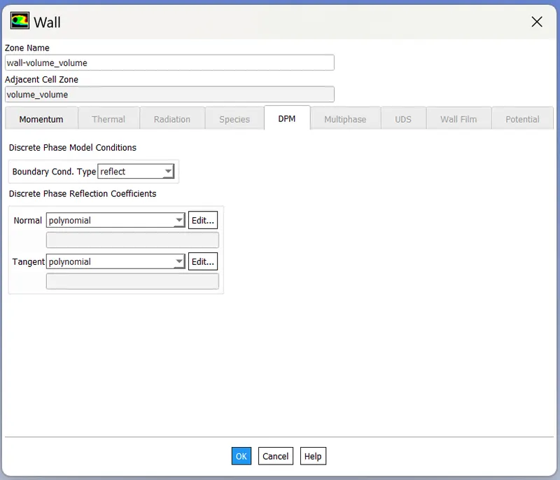
Inlet and wall:- Reflect
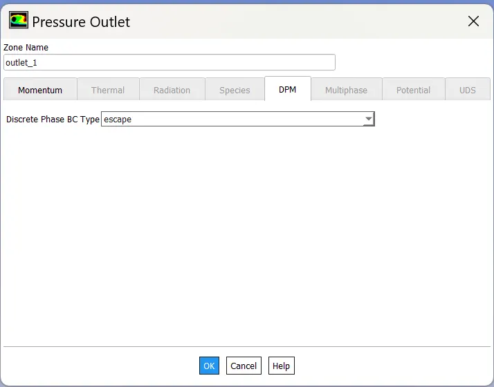
Outlet(Top):- Escape
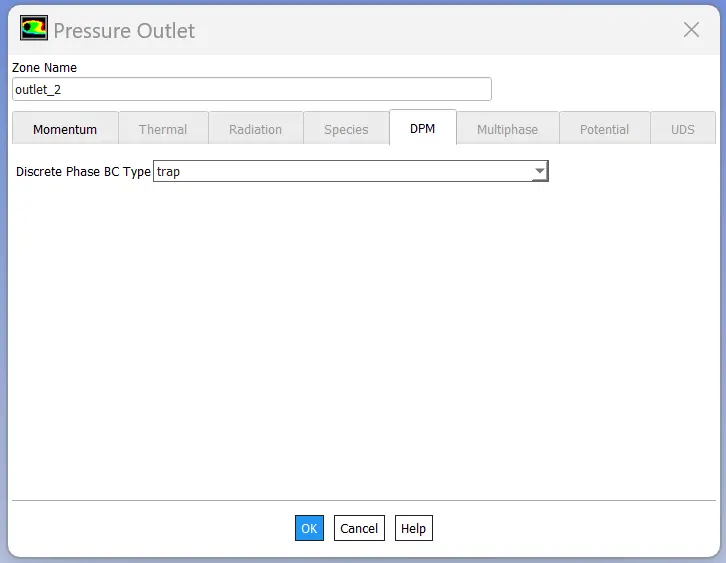
Outlet(Bottom/dustbin) - Trap
Note:
Structural mesh gives the best results, so you can use cutcell meshing approach available in Ansys Meshing.
Your Answers
Aim: To perform analysis on cyclone seperator and to calculate the seperation efficiency and pressure drop.
Theory:
What is a Cyclone Seperator?
Cyclone separators or simply cyclones are separation devices (dry scrubbers) that use the principle of inertia to remove particulate matter from flue gases.
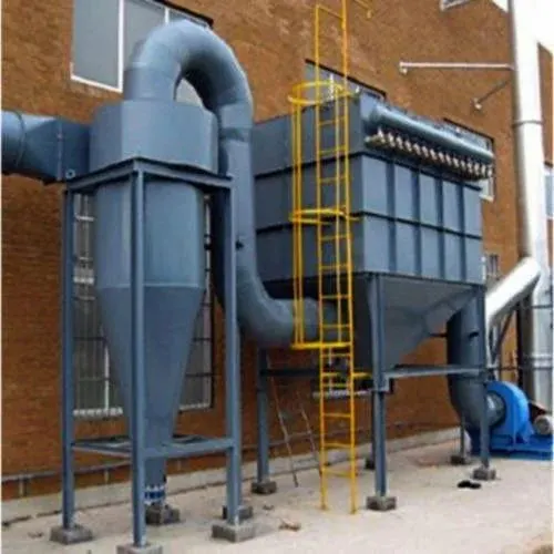
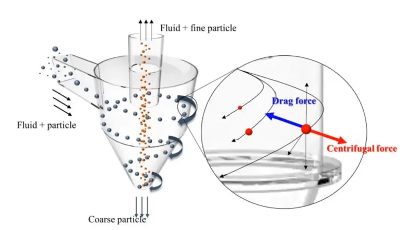
In a cyclone separator, dirty flue gas is fed into a chamber. The inside of the chamber creates a spiral vortex, similar to a tornado. The lighter components of this gas have less inertia, so it is easier for them to be influenced by the vortex and travel up it. Contrarily, larger components of particulate matter have more inertia and are not as easily influenced by the vortex.
The heavier particulate matter due to dominating centrifugal force is pushed against the walls where it either traps or falls down under the combined effect of gravity. The lighter components are limited to core of vortex due to negligible centrifugal force and are forced to escape in upward direction due to low pressure at the outlet and low density.
Where and Why Cyclone Seperators are used?
Cylone seperators are generally imployed in almost every type of industry like cement industries, wood inustry, anti-pollution device industries, etc.
Cyclone separators is one of many air pollution control devices known as precleaners since they generally remove larger pieces of particulate matter. This prevents finer filtration methods from having to deal with large, more abrasive particles later on.
Since there are no moving parts in cyclone seperator along with its easy contruction and zero to low maintenance cost these are one the sought after solution for filtering unwanted or harmful particulate matters from a running stream of fluid.
Setup:
Case is setup in project schematic 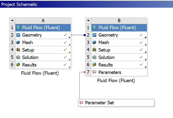
- Setting up Geometry
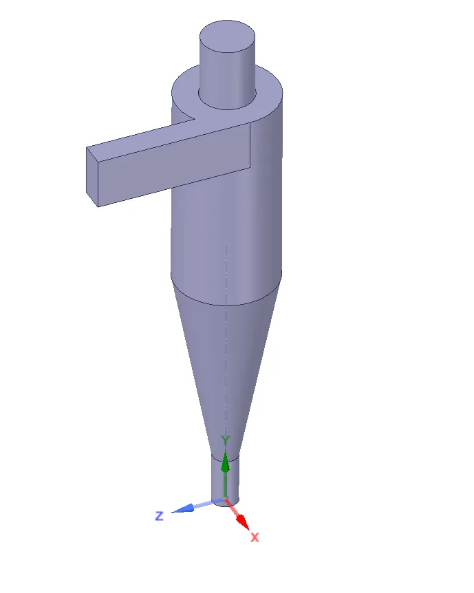
The geometry is imported in the space claim and volume is extracted. Since we dont need the solid boundaries for the simulaton we dont enable the share topology.
- Meshing:
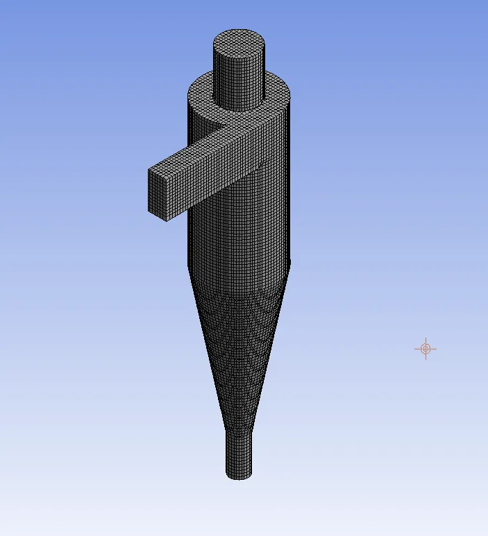
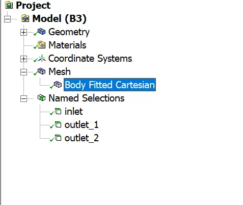
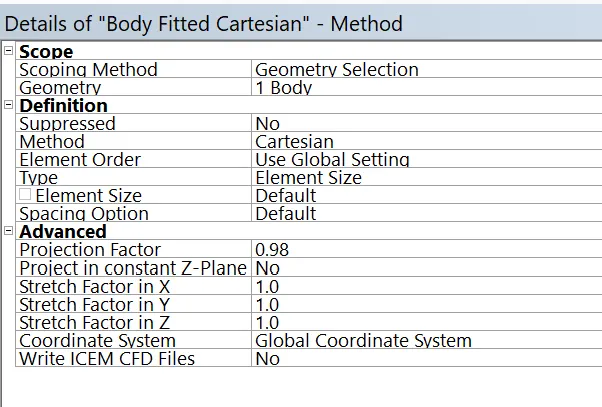
The ''Body Fitted Cartesian'' method is selected for meshing.
What and Why Body Fitted Cartesian Method?
As the name suggest it is a Body Ftiited Mesh, meaning that the mesh fits perfectly with the geometry, reducing the number of inaccuracies that propagate through the rest of the domain. And these elements are alligned with the cartesian directions. Because of this, the cut-cell Cartesian approach makes handling complex and moving geometries much easier and accurate by cutting the cells rather than stretching and compressing the cells to fit. Cut-cell because the mesh is cut to fit the geometry rather than compressing or skewing the elements.
Other advantages are:
Because this method cuts the volume cells at the wall, the mesh resolution is then independent of the geometry resolution. In other words, one can have a high fidelity geometric representation and a very coarse mesh. This can help speed up run-time calculations for one-off “let’s see what happens” designs ultimately aiding in rapid virtual prototyping.
Skewness is an inherent issue whenever you have a moving boundary using traditional meshing methods. This is not the case for the cut-cell Cartesian method. The mesh remains stationary and as the geometry moves the cells are cut and no compressing or stretching of the volume mesh occurs. This lack of skewness increases accuracy of the results and makes it the preferred method when dealing with moving geometries.
The other benefit of the cut-cell Cartesian method is added cell refinement at the wall, as this will have a positive impact on accuracy. With other methods, the full grid needs to be provided as an input and the actual surface geometry is no longer available. As a result, the accuracy of the surface location is limited by the resolution in the original grid. Any grid refinement performed during the simulation will cut the existing cells, and any resolution added near walls will not result in a better representation of the actual geometry. On the other hand, using the cut-cell Cartesian method requires the original surface information to be maintained. Thus, grid refinements will improve accuracy in the near-wall flow predictions. - Setup:
Following options were opted for the simulation
Gravity Enabled (-9.81 m/s2) Solver Steady Solver Type Pressure Based Model Discrete Phase Model Interaction Interaction with Continous Phase DPM Iteration Interval 10 Injection Type Surface >Inlet Material Anthracite Diameter 1 micron to 10 micron (parameter) Diameter Distribution Uniform Velocity 1m/s to 5 m/s (parameter) DPM boundary condition (inlet) Reflect DPM boundary condition (outlet_1) Escape DPM boundary condition (outlet_2) Trap DPM boundary condition (walls) Reflect Particle Type Inert Initializing Hybrid Iterations 300
A fundamental assumption made is that the the dispersed phase occupies <10% of the volume. If this condition is not met then Discrete Phase Modelling will not be valid.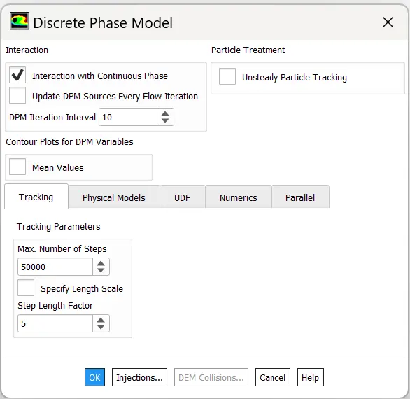
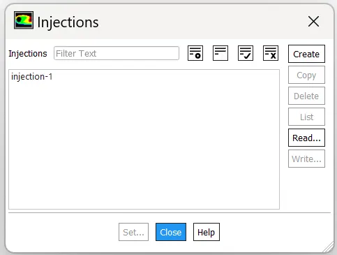
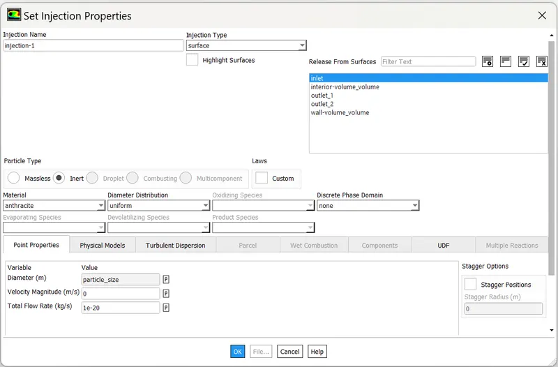
Interactions with Continous Phase must be enabled:
If one disables interaction with continuous phase, the coupling is 1-way. That means the particle trajectory is influenced by forces acting on the particle from the fluid, but the fluid flow is not influenced by the particles. FLUENT integrates the force balance on the particle; the integration routine is chosen depending on you own settings.
If one enables interaction, the fluid flow is influenced by the momentum of the particles as well. Within a timestep, the fluid trajectory is solved, then the particle trajectory based on that fluid flow. The fluid flow is then updated, based on the particle motions, and afterwards the particle positions are recalculated, on and on until the situation converged within the set residuals.
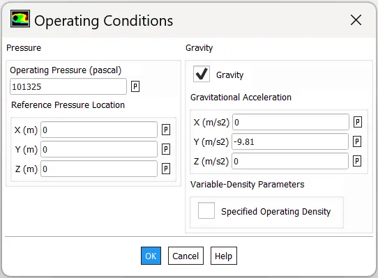
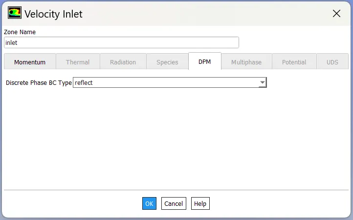

- Results:
Overall plots looks similar for all the cases with some noticible differences in magnitudes of some parameters like pressure; Number of particles trapped, escaped and incomplete.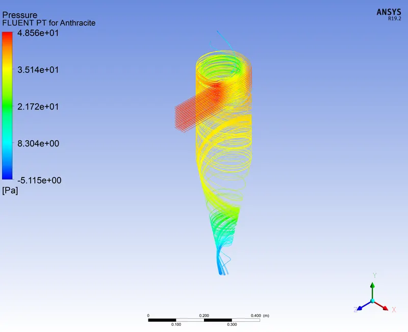
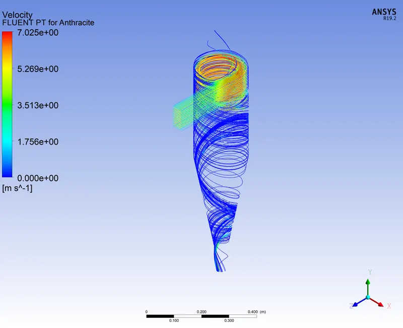
pressure streamline (5 m/s & 10μm velocity streamline (5 m/s & 10μm)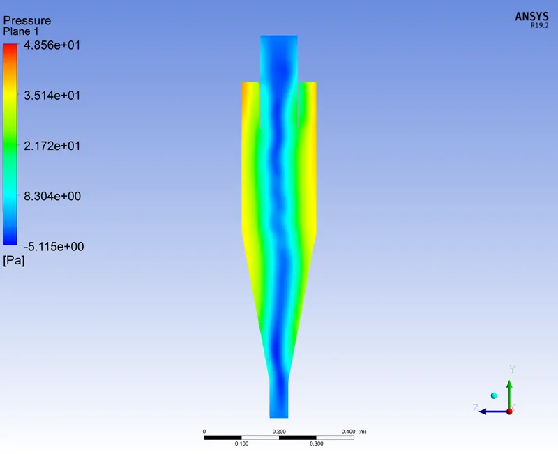
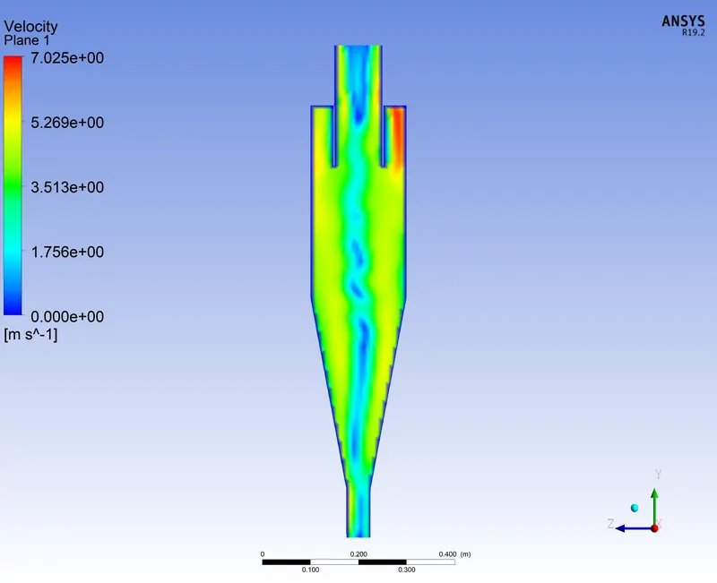
pressure contour (5 m/s & 10μm) velocity contour (5 m/s & 10μm)
Since all cases resutlts in ssimilar plot the results can be surmarised as follows:
Inlet Velocity (m/s) Particulate Matter Size (μm) Maximum Pressure (Pa) Minimum Pressure (Pa) Maximum Velocity (m/s) 1 5 1.868 -0.347 1.3854 3 5 17 -2 4.17 5 1 48.6 -5.11 7.026 5 3 48.5 -5.12 7.02 5 5 48.5 -5.11 7.02 5 10 48.5 -5.11 7.02 10 5 202.35 -20 14.18
Inlet Velocity (m/s) Particulate Matter Size (μm) Total Tracked Particles Trapped Particles Escaped Particles Incomplete Particles Efficiency 1 5 91 12 36 43 `~~13%` 3 5 91 60 26 5 `~~66%` 5 1 91 40 40 11 `~~44%` 5 3 91 52 30 9 `~~57%` 5 5 91 66 24 1 `~~72.5%` 5 10 91 80 11 0 `~~88%` 10 5 91 66 25 0 `~~72.5%` - Animations:
- Conclusion:
- From the plots in results it is seen pressure at inlet is maximum and lowest at 2 outlets which is intuitive and correct as flows moves from higher pressure region to lower pressure regions.
- The inner core region is having the lowest pressure as in a cyclone. This is due to low centrifugal forces due to low rotation speeds of the lighter particles.
- The pressure is maximum at the walls due to dynamic head converted to pressure head at the walls.
- The efficiency of cyclone seperator, defined as η=NtrappedNtracked increases as velocity and particle size increases, which is consistent with the simulation results.
- Models of Cyclone Seperator Efficiency
There are many models for calculating cyclone efficiency namely, IOZIA & LEITH Model, LI & WANG Model, KOCH & LICHT Model, LAAPLE Model.
- IOZIA & LEITH model assumes that the particle carried by the vortex endures the influence of two forces, a centrifugal force and a flow resistance.
- LI & WANG model includes particle bounce or re-entrainment and turbulent diffusion at the cyclone wall. This model is based on following assumptions:
- The radial particle velocity and radial concentration profile are not constant, for uncollected particles within the cyclones.
- Boundary conditions with the consideration of turbulent diffusion coefficient and particle bounce and re-entrainment on the cyclone walls are given by an emperical relation.
- The tangential velocity is related to radius of cyclone by uRn=constant.
- KOCH & LICHT Model recognized the inherently turbulent nature of cyclones and the distribution of gas residence times within the cyclone. The assumptions made in this model are:
- The tangential velocity of a particle is equal to the tangential velocity of the gas flow, i.e. there is no slip in the tangential direction between the particle and the gas.
- The tangential velocity is related to radius of cyclone by uRn=constant.
- LAAPLE Model was developed based on force balance without considering the flow resistance. Lapple assumed that a particle entering the cyclone is evenly distributed across the inlet opening. The particle that travels from inlet half width to the wall in the cyclone is collected with 50% efficiency.
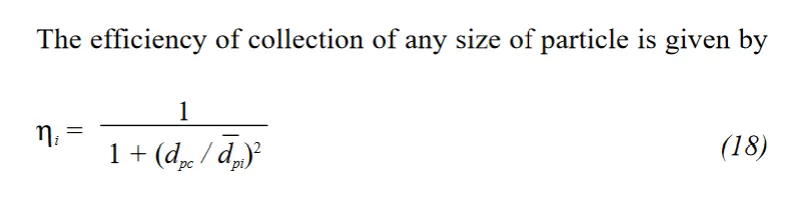
- IOZIA & LEITH model assumes that the particle carried by the vortex endures the influence of two forces, a centrifugal force and a flow resistance.
- References: