Week 8 - Simulating Cyclone separator with Discrete Phase Modelling
Aim:- To perform analysis on cyclone separator and calculate the separation efficiency and pressure drop.
ABSTRACT:
Writing the the empirical models used to calculate the cyclone separator efficiency. Performing an analysis on a given cyclone separator model by varying the particle diameter from 1 μm to 5 μm and calculate the separation efficiency in each case. Discuss the results. [Use both the velocity's as 3m/sec.]. Performing an analysis on a given cyclone separator model by varying the particle velocity from 1 m/sec to 5 m/sec and calculate the separation efficiency and pressure drop in each case. Discuss the results. [Use particle diameter size as 5 μm for all cases & keep flow velocity same as particle velocity]
INTRODUCTION:
Cyclone separators or simply cyclones are separation devices (dry scrubbers) that use the principle of inertia to remove particulate matter from flue gases. Cyclone separators is one of many air pollution control devices known as precleaners since they generally remove larger pieces of particulate matter. This prevents finer filtration methods from having to deal with large, more abrasive particles later on. In addition, several cyclone separators can operate in parallel, and this system is known as a multicyclone.
It is important to note that cyclones can vary drastically in their size. The size of the cyclone depends largely on how much flue gas must be filtered, thus larger operations tend to need larger cyclones. For example, several different models of one cyclone type can exist, and the sizes can range from a relatively small 1.2-1.5 meters tall (about 4-5 feet) to around 9 meters (30 feet)—which is about as tall as a three story building.[1]
Principle of Cyclone Seperator:
Centrifugation is the main principle involved in the separation of solids from fluids through cyclone separator. Such separation is done on the basis of particle size as well as particle density. Larger particles with greater density under the influence of centrifugal force are thrown outwards and are collected first then successive particles with relatively less size-and density are collected.[2]
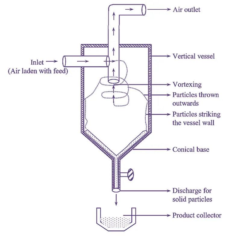
Empirical models used to calculate the cyclone separator efficiency:
- Iozia and Leith Model
Iozia and Leith logistic model is a modified version of Barth Model, which is developed based on force balance. The model assumes that a particle carried by the vortex endures the influence of two forces: a centrifugal force, Z and a flow resistance, W. The collection efficiency ηi of particle diameter
`d_(p i)` can be calculated from
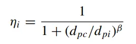
β is an expression for slope parameter derived based on the statistical analysis of experimental data of a cyclone with D = 170 0.25 m given as

and `d_(pc)` is the 50% cut size given by Barth
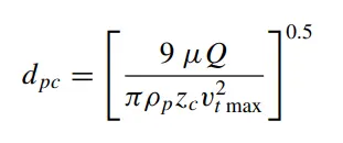
where core length, `z_c`, and core diameter, `d_c`, are given as
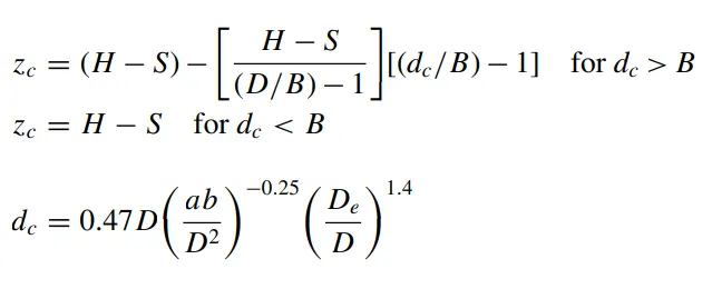
- Li and Wang Model
The Li and Wang [3] model includes particle bounce or re-entrainment and turbulent diffusion at the cyclone wall. A two dimensional analytical expression of particle distribution in the cyclone is obtained. Li and Wang model was developed based on the following assumptions:
• The radial particle velocity and the radial concentration
profile are not constant for uncollected particles within
the cyclone.
• Boundary conditions with the consideration of turbulent diffusion coefficient and particle bounce re-entrainment on the cyclone wall are:
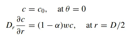
• The tangential velocity is related to the radius of cyclone by: u Rn = constant.
The concentration distribution in a cyclone is given as:

The resultant expression of the collection efficiency for particle of any size is given a
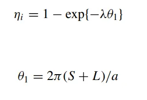
- Koch and Licht Model
Koch and Licht collection theory recognized the inherently turbulent nature of cyclones and the distribution of gas residence times within the cyclone. Koch and Licht described particle motion in the entry and collection regions with the additional following assumptions:
• The tangential velocity of a particle is equal to the tangential velocity of the gas flow, i.e. there is no slip in the tangential direction between the particle and the gas.
• The tangential velocity is related to the radius of cyclone by: u Rn = constant.
A force balance and an equation on the particles collection yields
the grade efficiency ηi
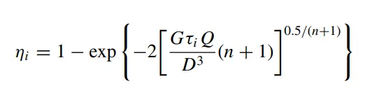
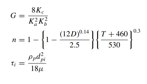
G is a factor related to the configuration of the cyclone, n is related to the vortex and `tau` is the relaxation term.[3]
- Lapple Model
Lapple model was developed based on force balance without considering the flow resistance. Lapple assumed that a particle entering the cyclone is evenly distributed across the inlet opening. The particle that travels from inlet half width to the wall in the cyclone is collected with 50% efficiency. The semi
empirical relationship developed by Lapple to calculate a 50% cut diameter, `d_(pc)`, is
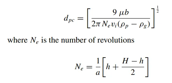
The efficiency of collection of any size of particle is given by

Now, setting up the geometry and physics:
- Importing the geometry to the spaceclaim:
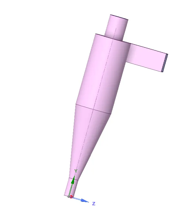
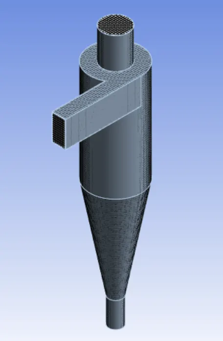
Extracting the fluid volume from the geometry and then opening the meshing.
Generating the mesh of 9mm with nodes as 59814 and elements as 52617.
Creating the named selection for inlet and outlet for boundary conditions:
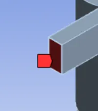
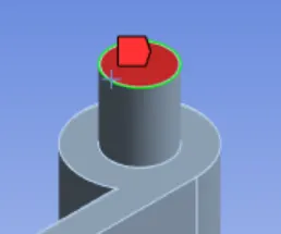
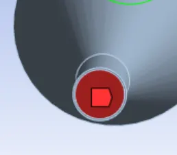
Inlet Outlet-2(Upper Part) Outlet-1(lower Part)
Now opening the setup and changing the parameters for simulation of the cyclone seperator.
Physics:
Solver - Pressure based
Time - Steady time.
velocity Formulation - Absolute
Gravitational Acceleration - Enabled in y-direction = -9.81.
Viscous Model -
Model - k-Epsilon
k-epsilon Model - RNG
RNG Option - Swirl Dominated Flow
Near Wall Treatment - Standard Wall Functions
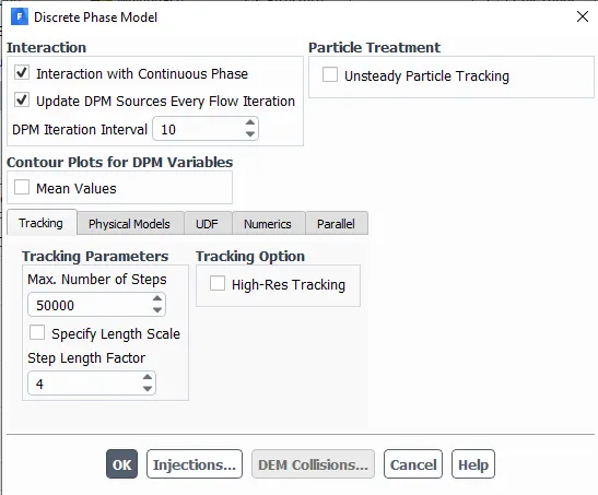
Discrete Phase Modelling (DPM):
Discrete Phase Modelling (DPM) is a method in which the flow of the discrete phase with a continuous flow is modeled. DPM is used to track individual particles through the continuum fluid. The Lagrangian discrete phase model follows the Euler Lagrange approach. The fluid phase is treated as a continuum by solving the Navier Stokes equation, while the dispersed phase is solved by tracking a large number of particle, bubble, or droplet through the calculated flow field. The dispersed phase can exchange momentum, mass, and energy with the fluid phase.
In this case, solid particle size ranging from 1µm to 5µm being simulated as a discrete phase in a continuum.
- Enabled interaction with continuous phase - to enable coupled flow
- Enabled update DPM sources every flow iteration - Enabling this option gives chances to calculate particle source term at every iteration.
- Contour plots for DPM variables - unenabled - Allows cell averaged variable value.
- Tracking parameters - Max. No. of steps - 50000 - It is the no. of timesteps that are used to compute a single particle trajectory.
- Specify length scale - This option is also used to control the timestep size.
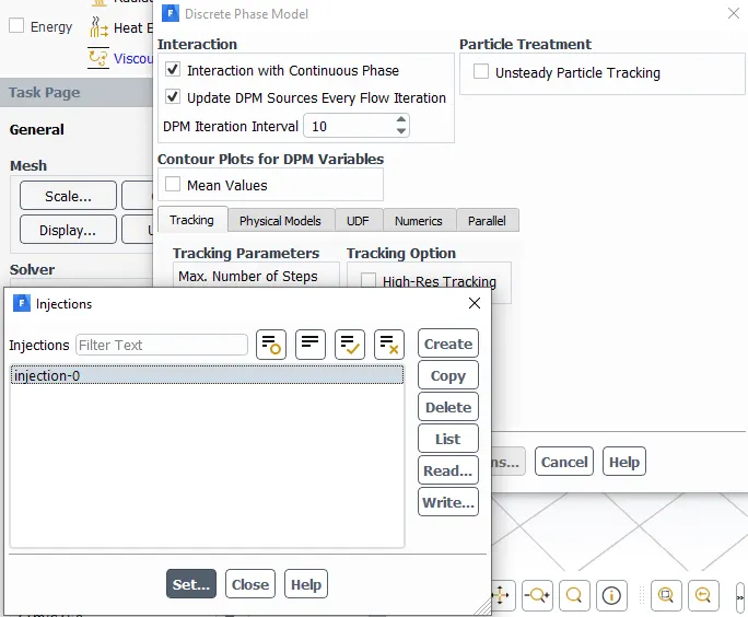
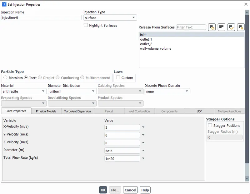
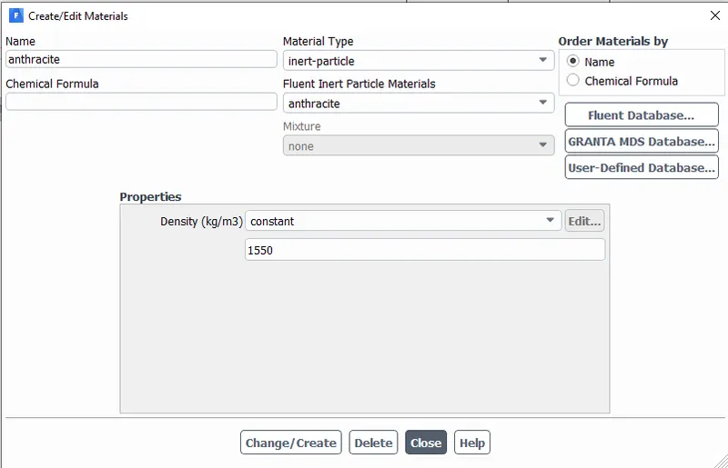
Material used: Anthracite (Dirty air which is to be filtered)
Inlet: - Velocity-Inlet
Velocity Magnitude -
Constant velocity of 3m/s.
DPM - Reflect
Reflect - The particle rebound off the boundary in question with a change in its momentum as defined by the coefficient of restitution.
Outlet 2- Pressure-Outlet
Pressure - 0 Pa
DPM - Escape
Escape - The particle is reported as having "escaped" when it encounters the boundary in question. Trajectory calculated are terminated.
Outlet 1 - Pressure-Outlet
Pressure - 0 Pa
DPM - Trap
Trap - The trajectory calculation are terminated and the fate of the particle is recorded as " trapped ". In the case of the evaporating droplet, their entire mass instantaneously passes into the vapour phase and enters the cell adjacent to the boundary. In the case of a combusting particle, the remaining volatile mass is passed into the vapour phase.[4]
Solution method and solution control:
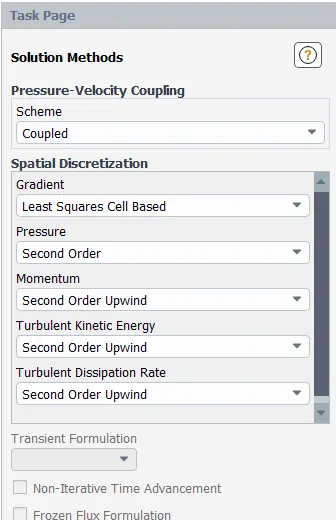
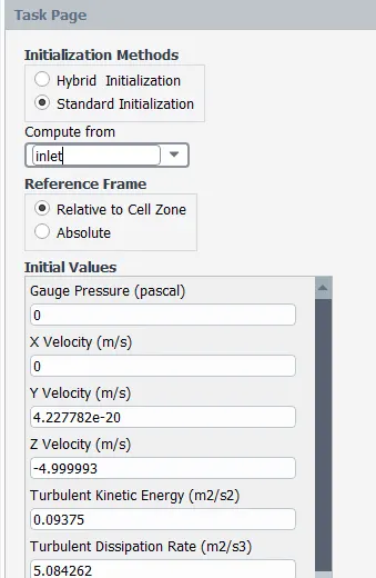
Standard Initialisation:
To perform an analysis on a given cyclone separator model by varying the particle diameter from 1 μm to 5 μm and calculate the separation efficiency in each case. Discuss the results. [Use both the velocity's as 3m/sec.]
Case 1] Diameter of Particle= 1e-6m
Velocity of paricle = 3m/s
Velocity of flow = 3m/s
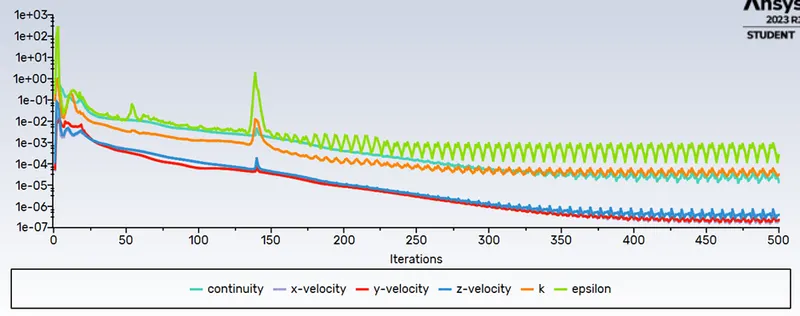
Residual:
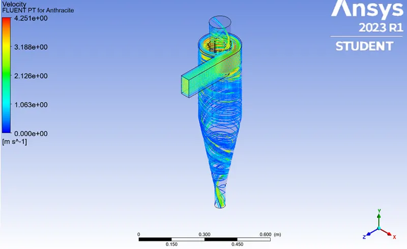
Velocity Contour of Particles:
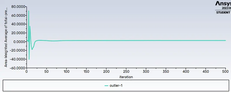
Area-Weighted average of pressure in inlet:

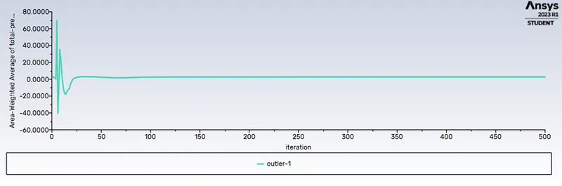
Area-Weighted average of pressure in outlet-1:
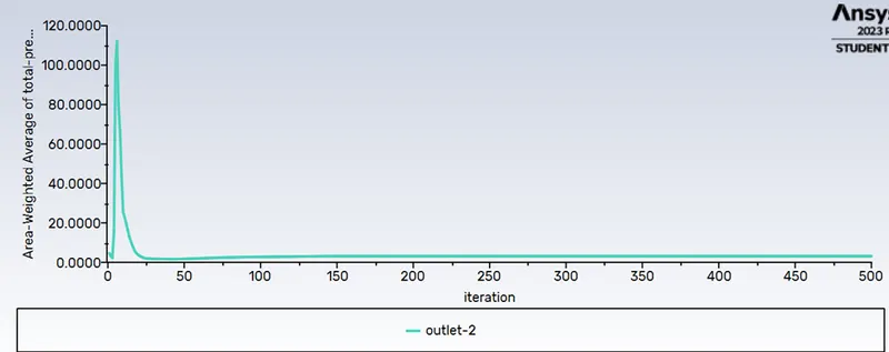
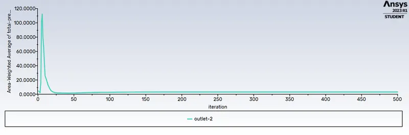
Area-Weighted average of pressure in outlet-2:
Total Particles tracked=91
Particles escaped=32
Particles trapped=59
efficiency= (particles trapped/total particles tracked)*100
`eta=p_(tc)/p_t*100`
`eta=59/91*100`
`eta=64.83%`
Case 2) Diameter of Particle= 3e-6m
Velocity of paricle = 3m/s
Velocity of flow = 3m/s
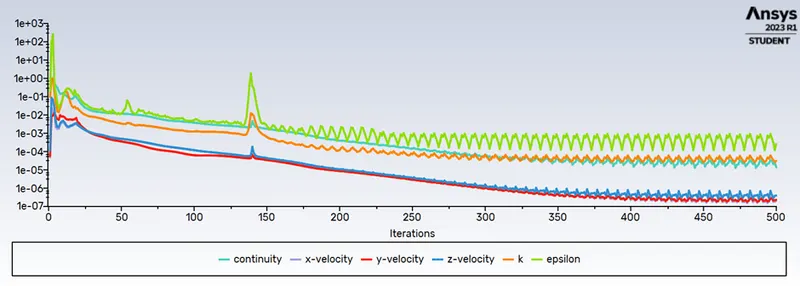
Residuals:
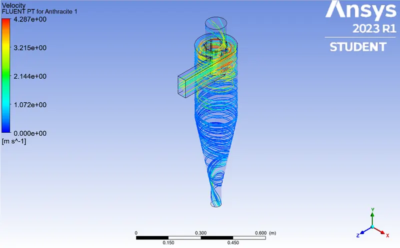
Velocity Contour of Particles:
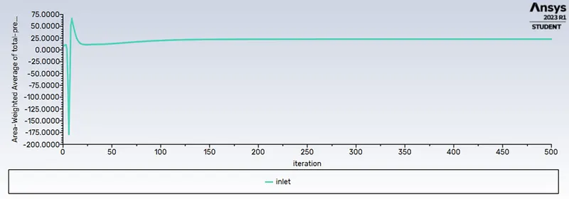
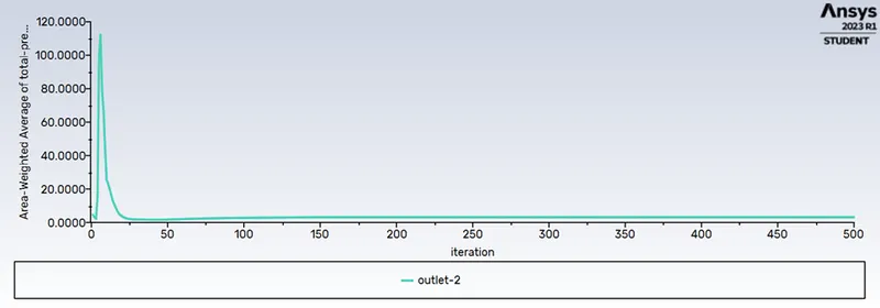
Area-Weighted average of pressure in inlet:
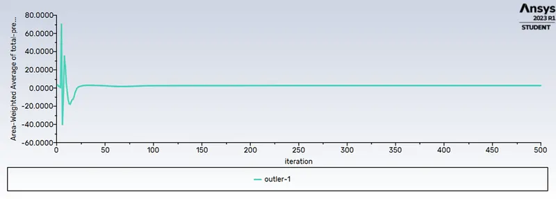
Area-Weighted average of pressure in outlet-1:
Area-Weighted average of pressure in outlet-2:
Total Particles tracked=91
Particles escaped=31
Particles trapped=60
efficiency= (particles trapped/total particles tracked)*100
`eta=p_(tc)/p_t*100`
`eta=60/91*100`
`eta=65.93%`
Case 3) Diameter of Particle= 5e-6m
Velocity of paricle = 3m/s
Velocity of flow = 3m/s
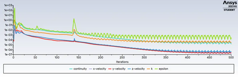
Residuals:
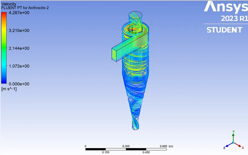
Velocity Contour of Particles:
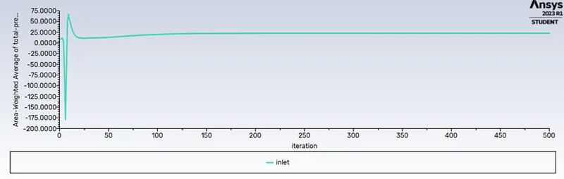
Area-Weighted average of pressure in inlet:
Area-Weighted average of pressure in outlet-1:
Area-Weighted average of pressure in outlet-2:
Total Particles tracked=91
Particles escaped=37
Particles trapped=54
efficiency= (particles trapped/total particles tracked)*100
`eta=p_(tc)/p_t*100`
`eta=54/91*100`
`eta=59.34%`
To perform an analysis on a given cyclone separator model by varying the particle velocity from 1 m/sec to 5 m/sec and calculate the separation efficiency and pressure drop in each case. Discuss the results. [Use particle diameter size as 5 μm for all cases & keep flow velocity same as particle velocity]
Case 1) Diameter of Particle= 5e-6m
Velocity of paricle = 1m/s
Velocity of flow = 1m/s
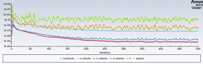
Residuals:
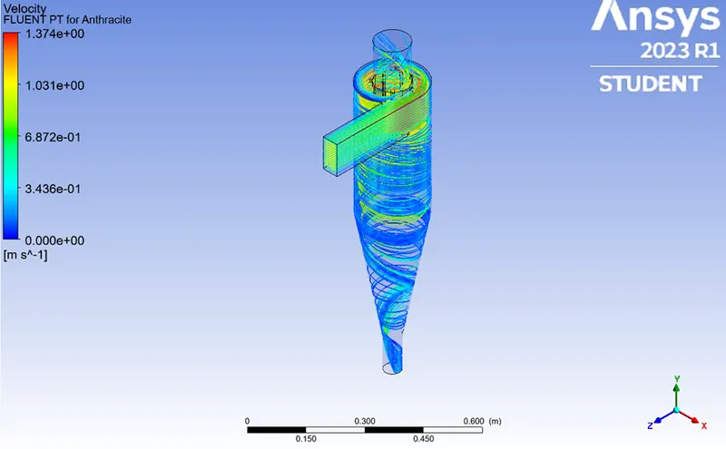
Velocity contour of paricles:
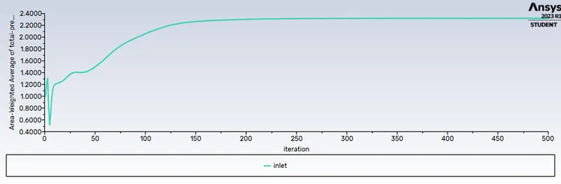
Area-Weighted average of pressure in inlet:
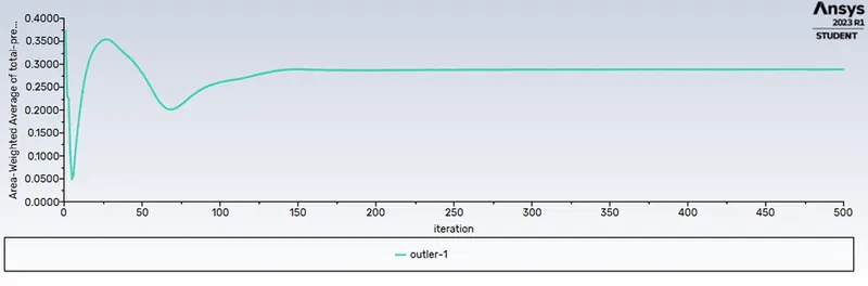
Area-Weighted average of pressure in outlet-1:
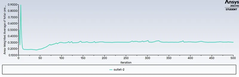
Area-Weighted average of pressure in outlet-2:
Total Particles tracked=91
Particles escaped=23
Particles trapped=68
efficiency= (particles trapped/total particles tracked)*100
`eta=p_(tc)/p_t*100`
`eta=68/91*100`
`eta=74.72%`
Pressure drop= Inlet pressure - oulet pressure
Pressure drop= 2.2-0.25= 2.45 Pa
Case 2) Diameter of Particle= 5e-6m
Velocity of paricle = 3m/s
Velocity of flow = 3m/s
Residuals:
Velocity Contour of Particles:
Area-Weighted average of pressure in inlet:
Area-Weighted average of pressure in outlet-1:
Area-Weighted average of pressure in outlet-2:
Total Particles tracked=91
Particles escaped=37
Particles trapped=54
efficiency= (particles trapped/total particles tracked)*100
`eta=p_(tc)/p_t*100`
`eta=54/91*100`
`eta=59.34%`
Pressure drop= Inlet pressure - oulet pressure
Pressure drop= 25-0=25 Pa
Case 3) Diameter of Particle= 5e-6m
Velocity of paricle = 5m/s
Velocity of flow = 5m/s
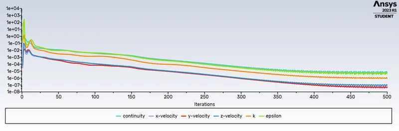
Residuals:
Velocity Contour of Particles:
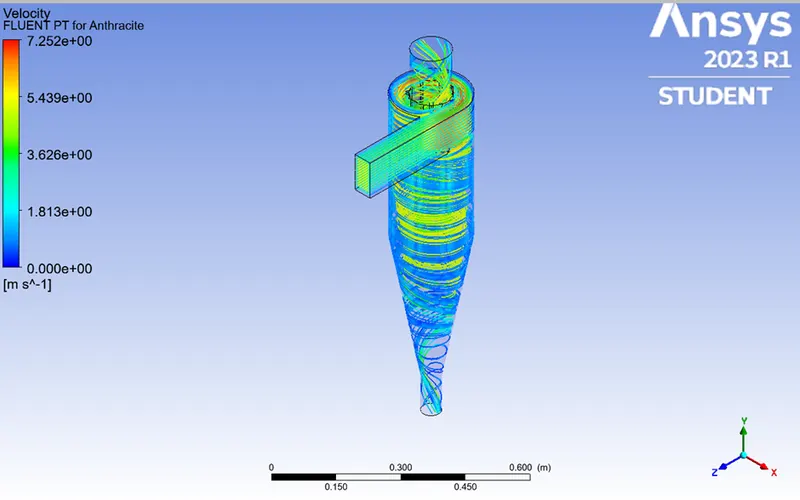
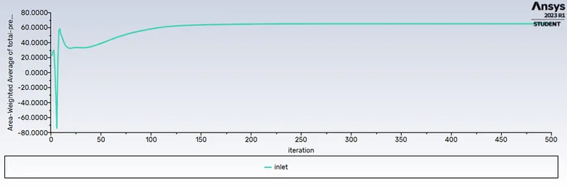
Area-Weighted average of pressure in inlet:
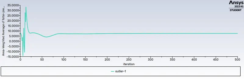
Area-Weighted average of pressure in outlet-1:
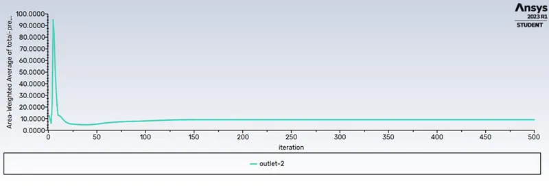
Area-Weighted average of pressure in outlet-2:
Total Particles tracked=91
Particles escaped=37
Particles trapped=54
efficiency= (particles trapped/total particles tracked)*100
`eta=p_(tc)/p_t*100`
`eta=54/91*100`
`eta=59.34%`
Pressure drop= Inlet pressure - oulet pressure
Pressure drop= 59-8=51 Pa
Conclusion:
- Both the parts simulated above show that Separation efficiency depends on both the diameter and velocity of the particles. As increased diameter and velocity gives increased separation efficiency.
- Velocity has a greater impact as compared to the diameter of the particle.
- Pressure drop is dependant on velocity. For constant velocity with varying diameter sizes, the pressure drop remains almost constant.
- Increased velocity causes a higher pressure drop.
References:
[1]:Cyclone separator - Energy Education
[3]:A CFD Study on the Prediction of Cyclone Collection Efficiency :Jolius Gimbun, Thomas S. Y. Choong, T. G. Chuah and A. Fakhru’l-Razi
[4]:Week 8 - Simulating Cyclone separator with Discrete Phase Modelling (skill-lync.com)