Week 8 - Simulating Cyclone separator with Discrete Phase Modelling
Aim : To perform analysis on cyclone separator and calculate the separation efficiency and pressure drop. Verify the effects of varying phase particle diameter and change in velocity of fluid and particles on the cyclone efficiency and pressure drop.
Objective:-
- To write a few words about any four empirical models used to calculate the cyclone separator efficiency.
- To perform an analysis on a given cyclone separator model by varying the particle diameter from 1 μm to 5 μm and calculate the separation efficiency in each case. Discuss the results. [Use both the velocity's as 3m/sec.]
- To perform an analysis on a given cyclone separator model by varying the particle velocity from 1 m/sec to 5 m/sec and calculate the separation efficiency and pressure drop in each case. Discuss the results. [Use particle diameter size as 5 μm for all cases & keep flow velocity same as particle velocity]
Aim : To perform analysis on cyclone separator and calculate the separation efficiency and pressure drop. Verify the effects of varying phase particle diameter and change in velocity of fluid and particles on the cyclone efficiency and pressure drop.
Objective:-
- To write a few words about any four empirical models used to calculate the cyclone separator efficiency.
- To perform an analysis on a given cyclone separator model by varying the particle diameter from 1 μm to 5 μm and calculate the separation efficiency in each case. Discuss the results. [Use both the velocity's as 3m/sec.]
- To perform an analysis on a given cyclone separator model by varying the particle velocity from 1 m/sec to 5 m/sec and calculate the separation efficiency and pressure drop in each case. Discuss the results. [Use particle diameter size as 5 μm for all cases & keep flow velocity same as particle velocity]
Thoery :
1.Cyclone Separator.
These are devices used to remove particulate matter from flue gases by using the principle of inertia. cyclone separators is one of many air pollution control devices known as precleaners since they generally remove large pieces of particulate matter.This prevents finer filtration methods from having to deal with large, more abrasive particles later on. In addition, several cyclone separators can operate in parallel, and this system is called as multicyclone. cyclones can vary drastically in size and the size largely depends on how much of flue gases much be filtered so larger operation need larger cyclones.
Working principle: cyclone separator works as a centrifuge but has continuous feed of dirty air . Dirty flue gases are fed into the chamber. The inside of the chamber creates a spiral vortex similar to a tornado. The lighter components of gas have less interia so it is easy for them to be carrried away by vortex and travel up.The heavier particles due to high inertia and weight they settle down at the bottom.
Larger particles have a tendency to settle down due to inertia and before that they hit the walls of the separator and fall down and collected in a hopper. Cyclone separator can remove particulate matter less than 10 micrometer in diameter. There are separator which can even remvove a particulate size of 2.5 micrometer..
Empircal models used in calculating cyclone separator efficiency:
1. Iozia and Leith model:
Iozia and leith logistic model is a modified version of Barth model, which is developed based on force balance. The model assumes that a particle carried by the vortex endures the influence of two forces that are centrifugal force Z and a flow resistance W. The collection efficiency ηi">ηiηi of particle diameter dpi can be calculated from
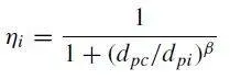
β">ββis an expression for slope diameter
2. Li and wang model:
The Li and wang model includes particle bouncing or entrainment and turbulent diffusion at cyclone wall. A two dimensional analytical expression of particle distribution in the cyclone is obtained.
Assumptions were made in making the model:
i.The radial particle velocity and the radial concentration profile are not constant for uncollected particles within the cyclone.
ii.Boundary conditions with the consideration of turbulent diffusion coefficient and particle bounce re- entrainment on the cyclone wall are:
The collection efficiency of particle of any size is given as:

3. Koch and litch model:
kotch and litch collection theory recognized the inherently turbulent nature of cyclones and the distribution of gas residence times within the cyclone. kotch and litch described the particle motion in the entry and collection regions with additional following assumptions:
- The tangential velocity of a particle is equal to the tan- gential velocity of the gas flow, i.e. there is no slip in the tangential direction between the particle and the gas.
- The tangential velocity is related to the radius of cyclone by: uR^n= constant.
Grade efficiency

4. Lapple model:
Lapple model was developed based on force balance without considering the flow resistance. Lapple assumed that a particle entering the cyclone is evenly distributed across the inlet opening. The particle that travels from inlet half width to the wall in the cyclone is collected with 50% efficiency. The semi empirical relationship developed by Lapple to calculate a 50% cut diameter.
The efficiency of collection of any size of particle is given by :
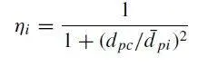
Here, Dpc is known as cut diameter.Cut Diameter is defined as the size of the particles collected with 50% efficiency.Cut diameter is one of the important indexes for evaluating dust performance in a cyclone separator. The smaller the cut diameter in a cyclone separator, the better is its dust performance.
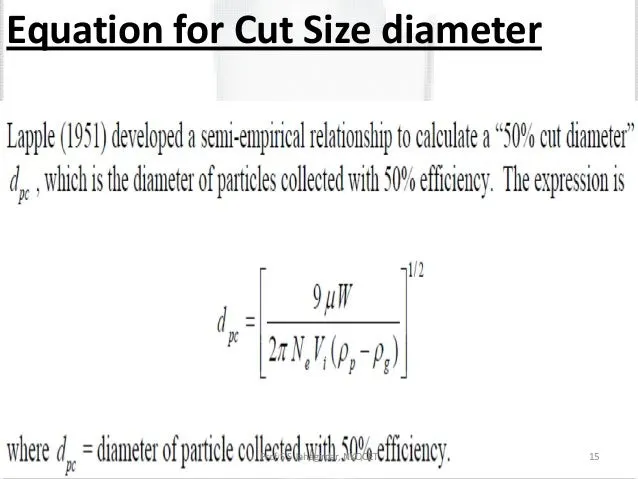
2.Discrete Phase Model : The Lagrangian discrete phase model in Ansys Fluent follows the Euler-Lagrange approach.The fluid phase is treated as a continuum ny solving the Navier-Stokes equation,while the dispersed phase is solved by tracking a large number of particles,bubbles or droplets through the calculated flow field. The dispersed phase can exchange momentum,mass and energy with the fluid phase.
A fundamental assumuption meade in this model is that the dispersed second phase occupies a low volume fraction(<10%).The particle or droplet trajectories are computed individually at specifed intervals during the fluid phase calculation.
Objective:-
- To write a few words about any four empirical models used to calculate the cyclone separator efficiency.
- To perform an analysis on a given cyclone separator model by varying the particle diameter from 1 μm to 5 μm and calculate the separation efficiency in each case. Discuss the results. [Use both the velocity's as 3m/sec.]
- To perform an analysis on a given cyclone separator model by varying the particle velocity from 1 m/sec to 5 m/sec and calculate the separation efficiency and pressure drop in each case. Discuss the results. [Use particle diameter size as 5 μm for all cases & keep flow velocity same as particle velocity]
Case Setup:
1.Spaceclaim geometry: Download the geometry of the cyclone separator from the provided link.
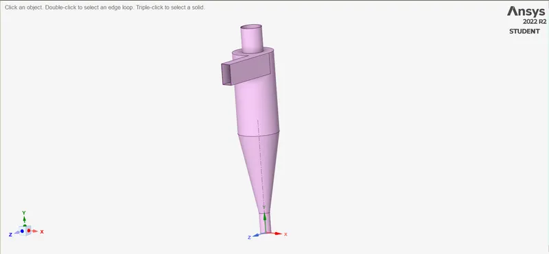 the geometry as downloaded.The simulation has to be done on the volume of the cyclone so we have to extract the fluid volume for the simulation.
to extract the volume go to workbecnch>volume extraction > select the edges of the fluid volume> ok
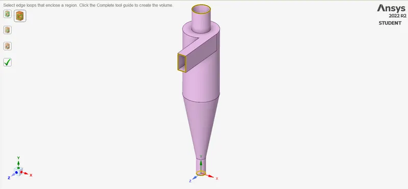
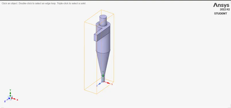 volume extraction done.as the volume is extracted we are readdy to mesh the model.
2. Meshing : For meshing the volume of the cyclone we will use the cartesian method. Becuase the high elemnt quality of the structural mesh is the reason to use this mesh.
for applying the cartesian method : mesh > insert method > selct the body > select the cartesian method > elemnt size = 6mm > mesh element size =6mm >generrate mesh.
Number of elements for 6mm mesh lenght is 93883
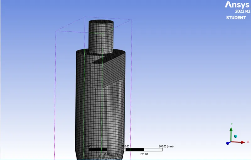
Element Quality
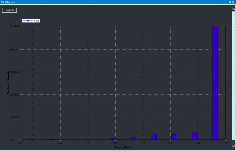
Also we have to give the name selection for the geometry. so we have one Inlet , Top Outlet and Bottom Outlet
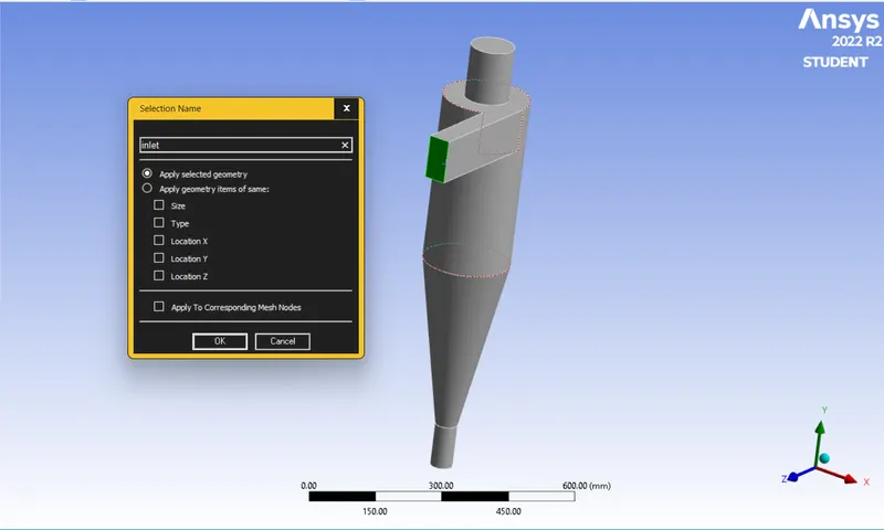
3. Case Setup :
- Solver : Pressure-Based
- Velocity : absolute
- State : Steady-state
- Gravity : Y = -9.81 m/s
Models :
- Turbulent Model : K-epsilon RNG,Swirl Dominated flow
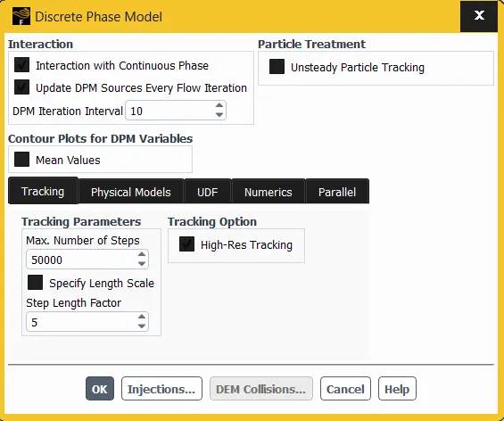
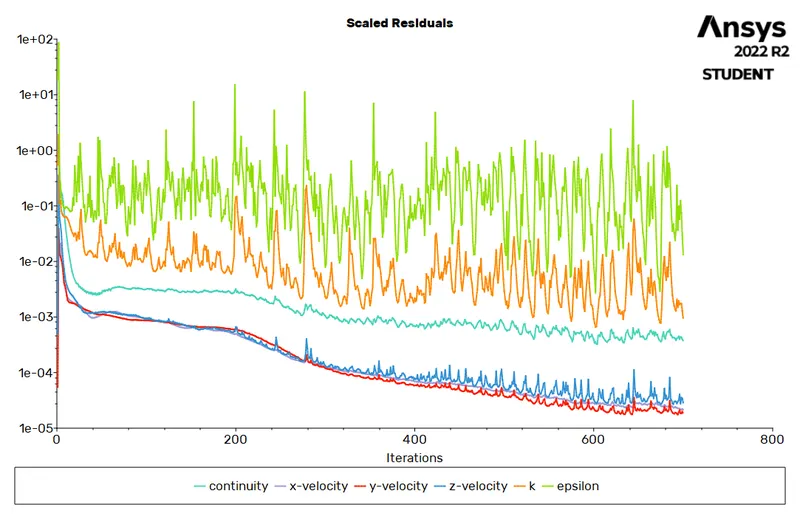
- Discrete Phase Model : We will set the DPM model as Coupled Flow where the discrete phse will interact with the continius phase. Also we will update the particle information after every 10 iterations.
For traking the particle we will keep the Tracking Parameters same.
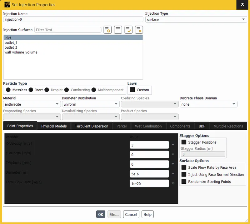
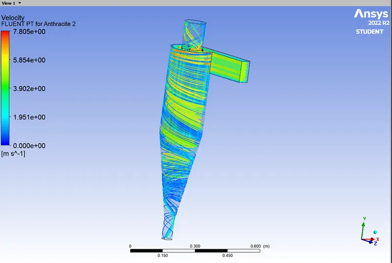
Now we will add the information for the inject particles. In the DPM > Injections > Create > Particle Type : Anthracite ,Injection Type : Surface ,Realese from the surface : Inlet > Point Properrties : Diameter = 5e-6 m and velocity : X-velocity = 3m/s (the velocity we specify here will act normal to the surface selected for the Release for the particle)> Ok > Close
- Boundary Conditions :
- Inlet : velocity-inlet and DPM Boundary Conditions = reflect
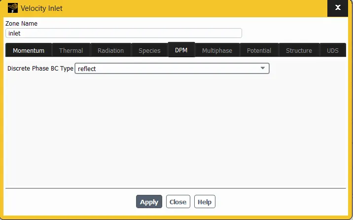
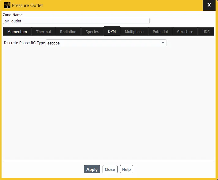
- Top/Air-Outlet : pressure outlet and DPM condition = escape.
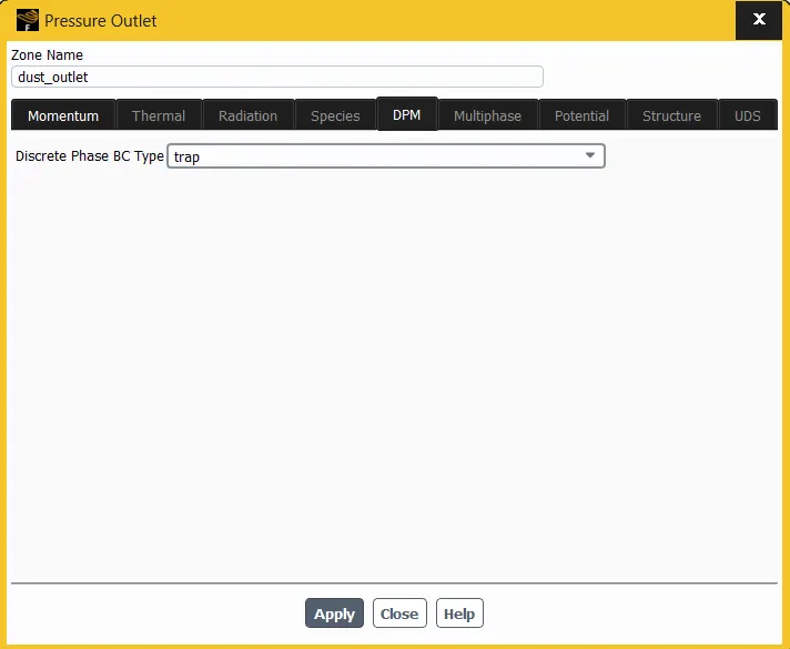
- Bottom/Trash Outlet : pressure-outlet and DPM condition = trap.
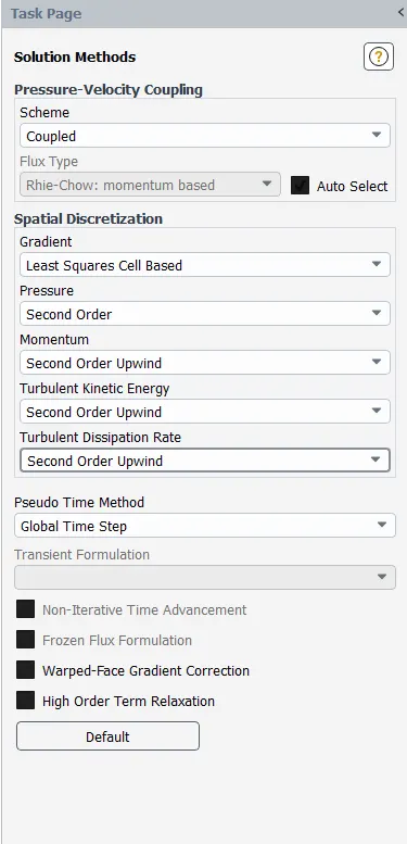
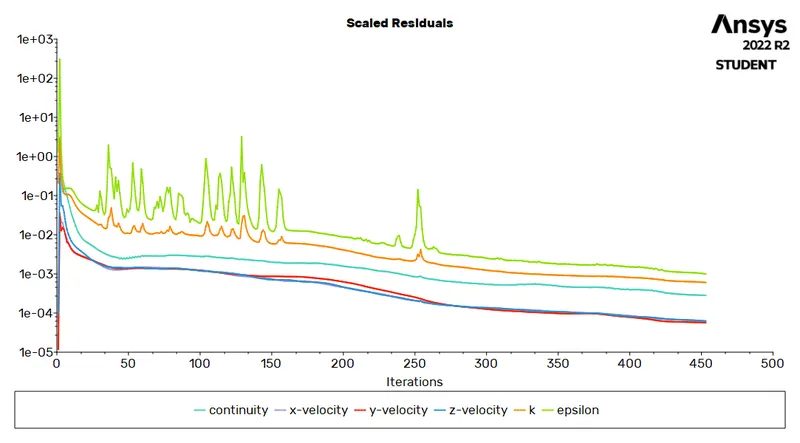
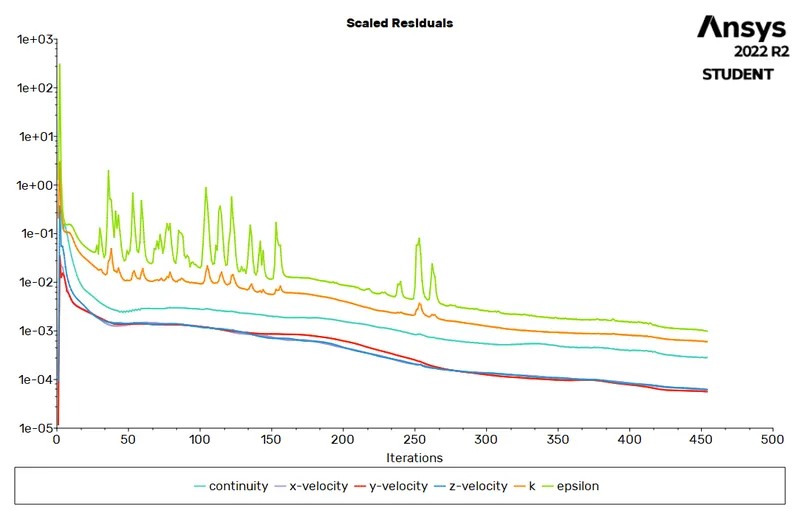
As the models are set and the boundary conditions are set we will initialize the setup with Standard Initialization form inlet.
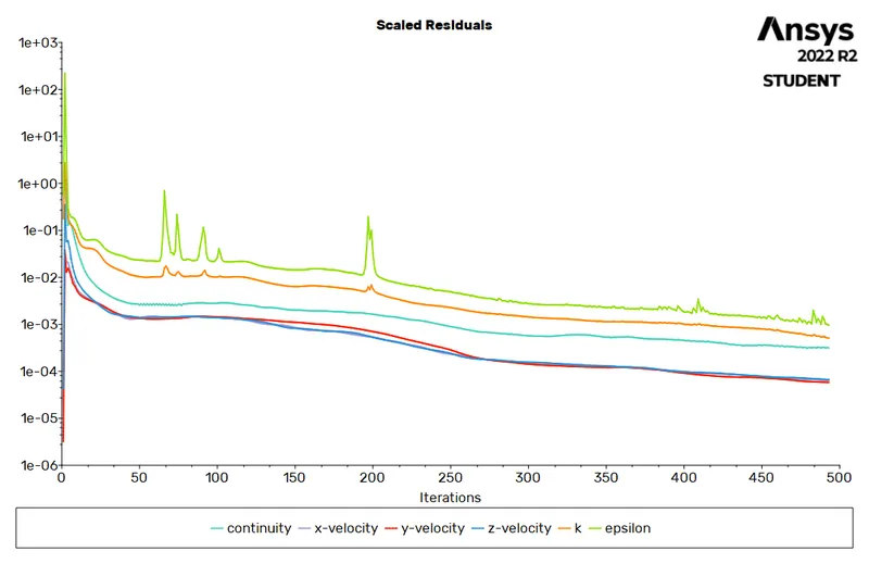
Set the methods as SIMPLE
plot the results with varying particle diameter size and with different velocities and show the change effects in the efficiency and pressure drop.
Results :
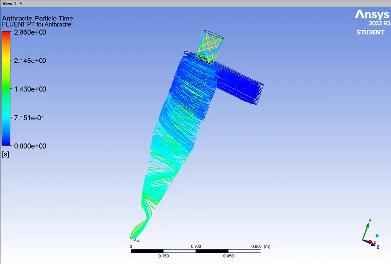
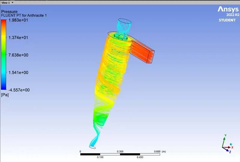
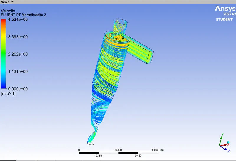
- Case 1. Constant Velocity of the particle and fluid as 3 m/s and and Particle diameter as 1,3 and 5 mcron meter.
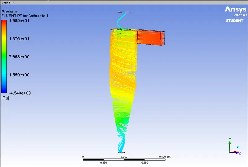
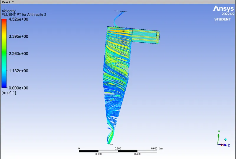
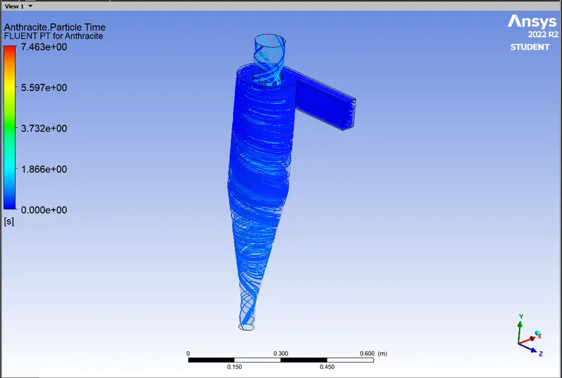
Case 1(a) : Particle Diameter = 5e-6 m
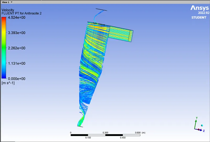
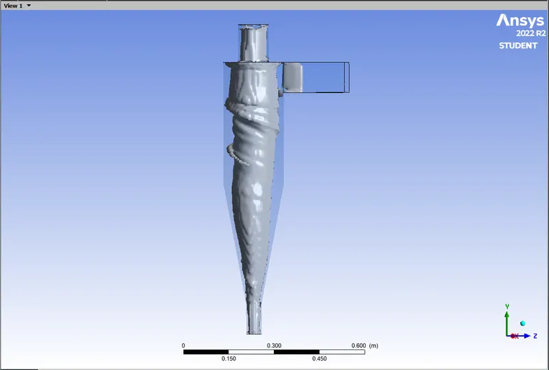
Particle Tracked = 136 , Esccaped = 35 , Trapped = 101
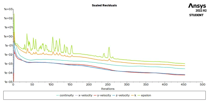
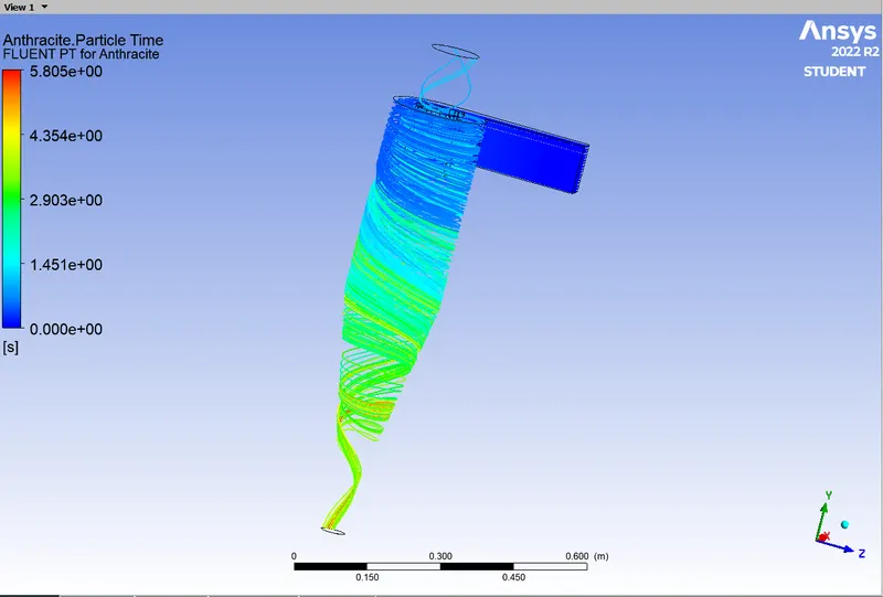
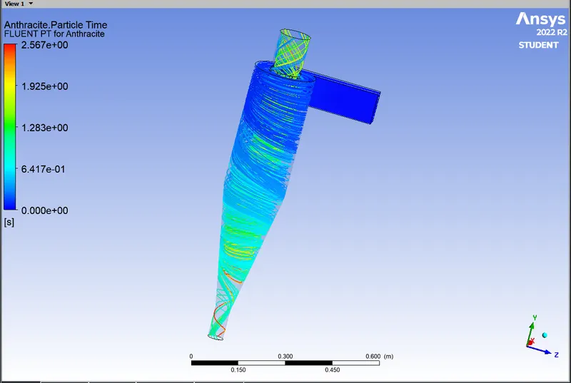
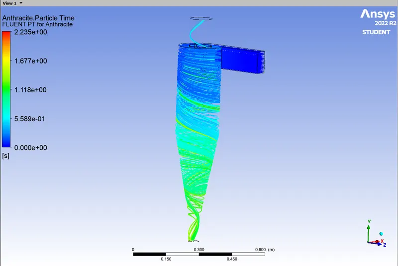 Particle Time.
Case 1(b) : Particle Diameter = 3e-6 m
Particles Tracked = 136 , Escaped = 5 , Trapped = 131
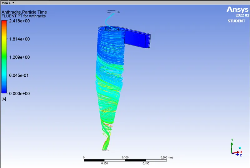
Case 1(c) : Particle Diameter = 1e-6 m
Particle Tracked = 136 , Escaped = 8 , Trapped = 128
No.of Cases Diameter No.of particles Efficiency Pressure drop
(microns) Tracked Escaped Trapped (Pa)
1 5 136 35 101 74.26% 18.87
2 3 136 5 131 96.32% 18.87
3 1 136 8 128 94.11% 18.87
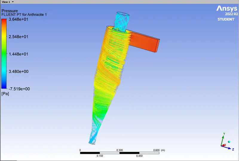
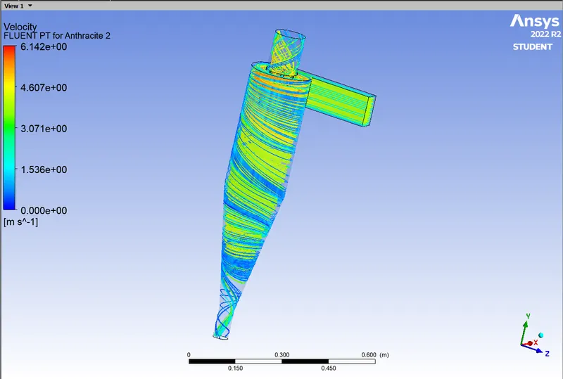
Case 2 : Constant Diameter of 5 micro and Velocity of 1,4 and 5 m/s.
Case 2(a) : Velocity of Fluid and Particle = 5 m/s
Particles Tracked = 136 , Escaped = 28 , Trapped = 92 , Incomplete = 15
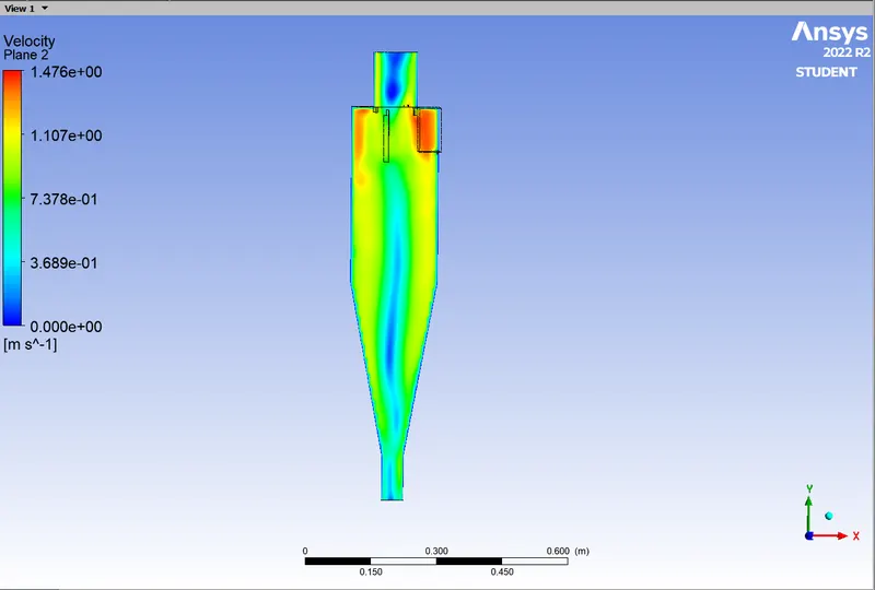
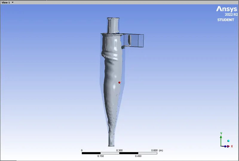
Case 2(b) : Velocity of Fluid and Particle = 4 m/s
Particles Tracked = 136 , Escaped = 49 , Trapped = 87
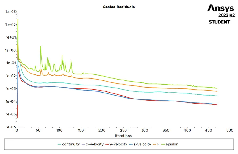
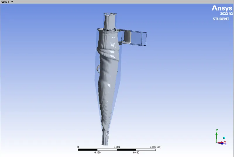
Case 2(c) : Velocity of Fluid and Particle = 1 m/s
Particles Tracked = 136 , Escaped = 9 , Trapped = 127
No. of cases Velocity of Fluid No.of Particles Efficiency Pressure Drop
& Particle (m/s) Escaped Trapped Incomplete (Pa)
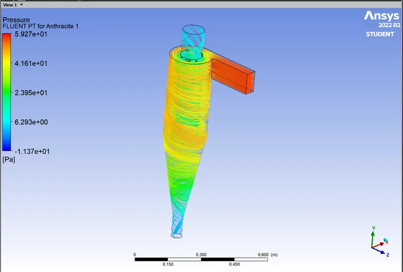
1 5 28 92 15 67.64% 56.23
2 4 49 87 0 64% 64.64
3 1 9 127 0 93.38% 2.03
Conclusion:
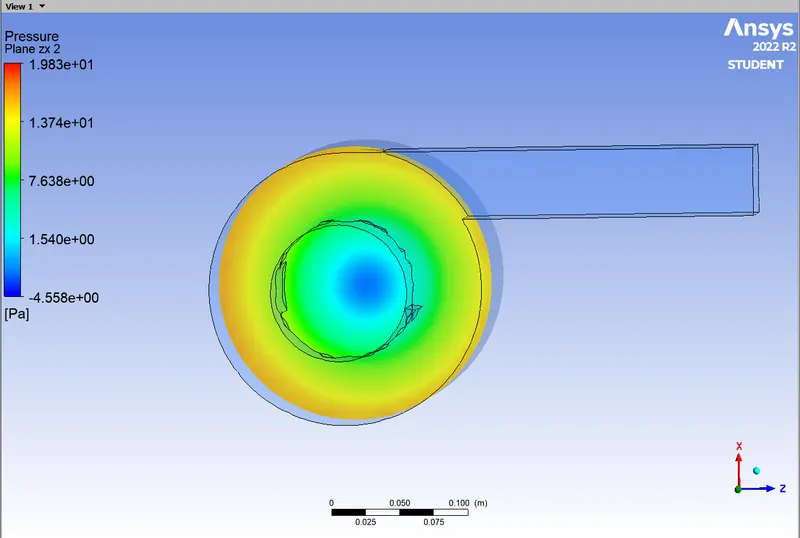
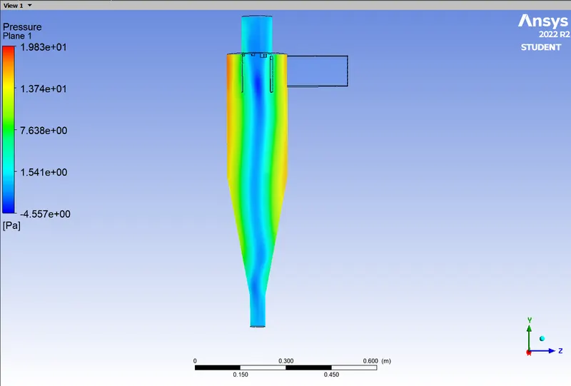
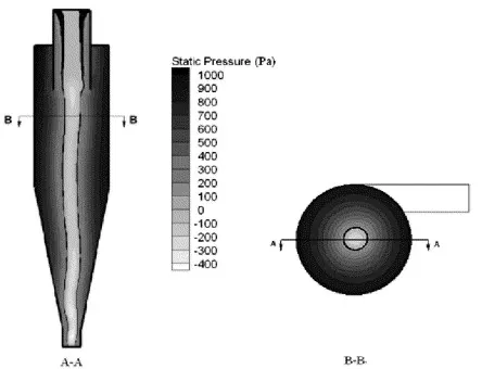 Pressure Results
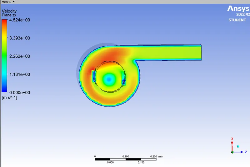
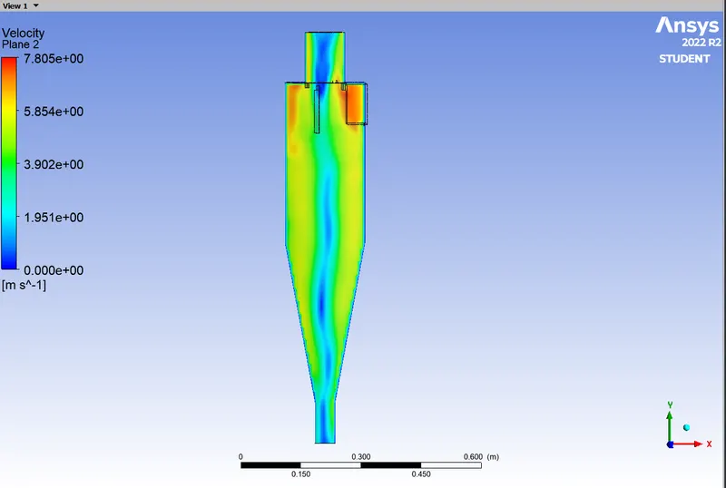
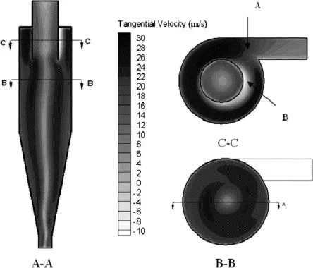 Velocity Results
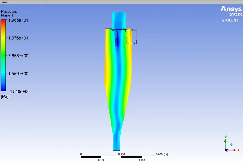
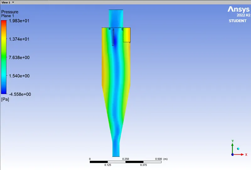
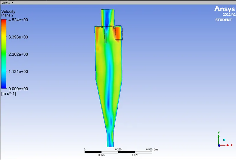
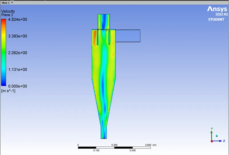
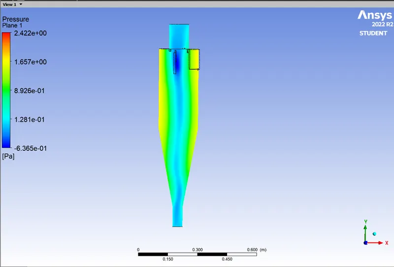
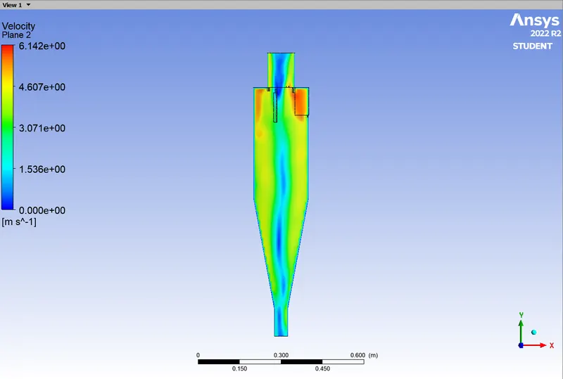
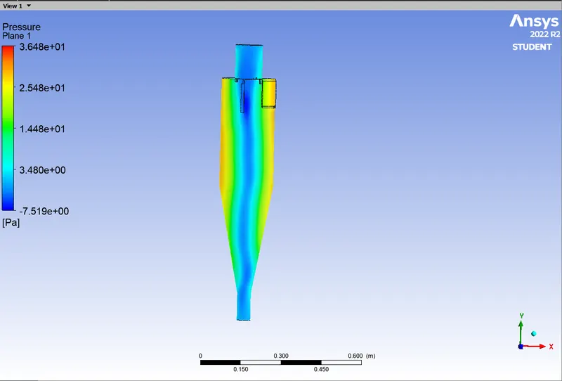
The results shown above are from the reasearch paper and cfd post results of pressure and tangential velocity respectively. From the results we can say that the results of the pressure and the tangentail velocity are in good agreement.
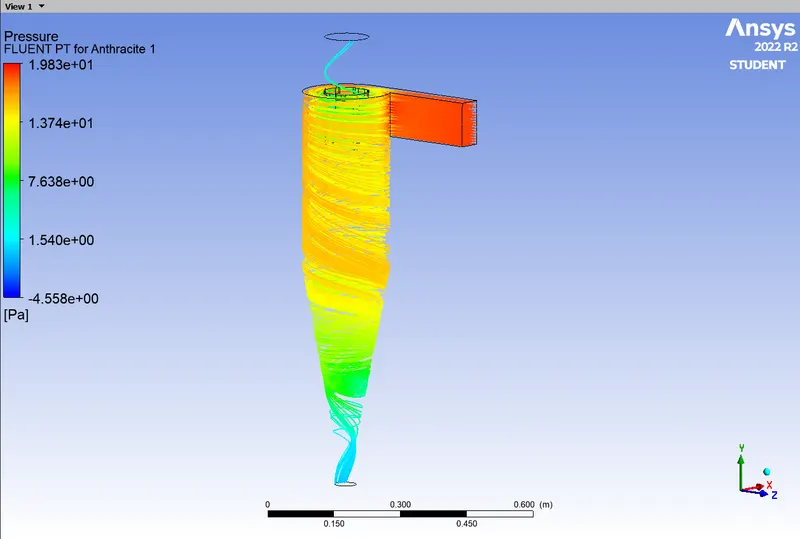
- The pressure contur of the cfd-post is seen to radially decreases from the wall to the center and we can see a negative pressure region in the centre, the same can be seen in the experimental results.
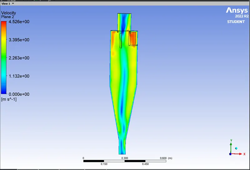
- The velocity in the cyclone is tangential velocity and it is zero on the wall as well as in the centre of the flow field. From the figure C-C of the experiment it is shown that the inlet velocity is accelerated up to 1.5–2.0 times of the inlet velocity at point A. That same results is captured in the current cfd simulated result. In the CFD result we can see that the inlet region is in yellow colour which resemble the magnitude of velocity of 3.93 m/s and after travelling upto a certain point the velocity is incresed to 4.52 m/s that is shown in red colour, that is the velocity is increased by 1.5 time the inlet velocity. And then the velocity starts to decrease as it spins down the wall.
- We can also see that from the Case 2 a.b andd c that the pressure drop increases as the velocity of the fluid and particle increases.
- Although my computational for the efficiency is incoorect the original trend for the efficiency of the cyclone separator is that as the Particle Diameter is incresed the Efficiency of the cyclone should be increased beacuase the bigger the diameter of the particle the particle will go down beacuse of its inertia and we get trapped.
- And the same result with the inlet velocity
Refernce paper : https://www.sciencedirect.com/science/article/pii/S0307904X06000291