Week 8 - Simulating Cyclone separator with Discrete Phase Modelling
Aim
To perform analysis on cyclone separator and calculate the separation efficiency and pressure drop.
1. To perform an analysis on a given cyclone separator model by varying the particle diameter from 1 μm to 5 μm and calculate the separation efficiency in each case. Discuss the results. [Use both the velocity's as 3m/sec.]
2 .To perform an analysis on a given cyclone separator model by varying the particle velocity from 1 m/sec to 5 m/sec and calculate the separation efficiency and pressure drop in each case. Discuss the results. [Use particle diameter size as 5 μm for all cases & keep flow velocity same as particle velocity]
Introduction
Cyclone separators are separation instruments that segregate particles or particulate matter from a fluid medium, typically gaseous in nature, on the principle of inertia, density differences and gravity. The working process involves supplying the particle laden fluid as a continuous stream into the separator leading to the formation of a spiral vortex, almost assuming a tornado or cyclone based shape, whereby the lighter fluid component on account of lesser inertia rises due to the influence of the vortex while the more dense particulate matter having more inertia collides against the walls, similar to that of a centrifuge, and settles at the bottom of the same device from where they get collected and accordingly treated at a later stage.
Also, efficiency of cyclone separators is influenced by the size and amount of the particulate matter to be separated, exit pipe diameter and length to name a few with most of these devices typically aimed at 10 micrometres in particle size diameter and above, although high efficiency cyclones can filter particulate matter as small as 2.5 micrometres in diameter.
Common drawback is enabling of smaller particle size filtration which requires change in the existing standard design that suits the desired application.
Theory
Our objective is to calculate the efficiency of cyclone seperator setup we are using.
There are few empirical models used to calculate the cyclone separator efficiency like:-
1. Iozia and Leith Model
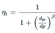
This model is developed on the concept of force balance [2] wherein it assumes that the particles conveyed by the vortex is acted upon by two forces; centrifugal and flow resistance forces. It's prediction of collection efficiency, ηi">ηiηi, for particle diameter, dp, is based on the following formula:
2. Li and Wang Model
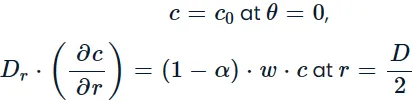
This model [4] implements the particle bounce or re-entrainment and turbulent diffusion effects at the walls of the separator based on the following assumptions:
- Radial particle velocity and radial concentration are not constant for uncollected particles within the device.
- Tangential velocity with respect to the radius of the cyclone is related as u⋅Rn=constant">u⋅Rn=constantu⋅Rn=constant.
- Boundary conditions including the presence of turbulent diffusion coefficient and particle bounce re-entrainment on the walls of the device is given as:
3. Koch and Licht Model
This model [5] acknowledges the pre-dominantly turbulent nature of flow within the cyclone separator and distribution of fluid residence times. Also, particle motion in entry and collection regions were described with the following supplementary assumptions:
- Tangential velocity of particle and gas flow are equal to each other i.e., no slip between the particles and gas flow in the tangential direction.
- Similar to the Li and Wang model, tangential velocity with respect to the radius of the cyclone is related as u⋅Rn=constant">u⋅Rn=constantu⋅Rn=constant.
This led to the development of the grade efficiency equation, ηi">ηiηi, with regards to the force balance and particle collection equations expressed as:

4. Lapple Model
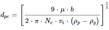
This model [6] like the Iozia and Leith Model and the Koch and Licht Model is based on force balance, however, without considering flow resistance. The model assumes that particles entering the cyclone are evenly distributed across the inlet. Particles travelling from the inlet half width to the walls of the separator is collected with 50% efficiency and the semi-empirical relationship to calculate 50% cut diameter, dpc">dpcdpc, is given by the following expression:
Solving & Modelling approach
The processof completeing the challenge will be done in following these 5 steps:-
1) Geometry - The geometry of the model will be formed where the actual flow will flow/interfere
2)Mesh - The meshing of the volume is done whoose parameters are set by default with help of 'Boundary Box'
3)Setup - The initial and boundary conditions or parameters and the model choosen are given to the model.
4) Solutions - Based on conditions and requirements the result is calculated with the help of model choosen
5) Results - The final results are appeared here from where the investigation of simulation is done.
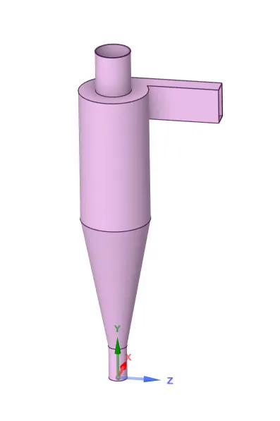
Step 0) Download and import the geometry model
Step 1) Prepare the geometry for meshing
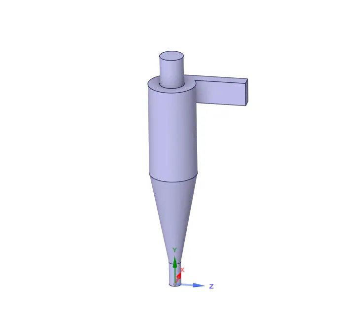
Step 2) Assign names to face and mesh the model
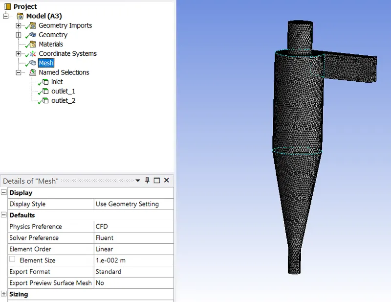
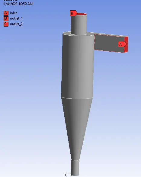
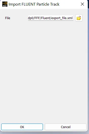
Step 3) Prepare the setup
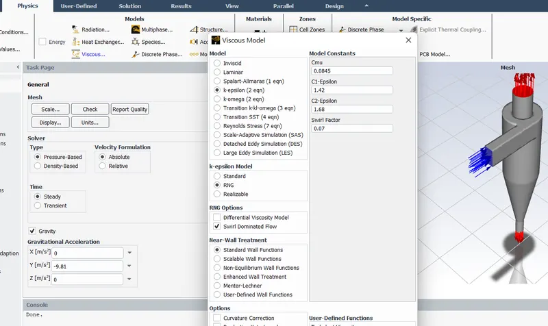
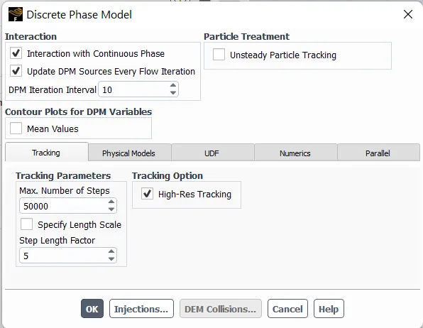
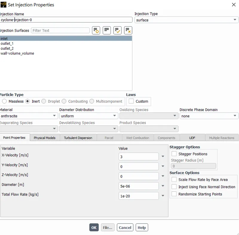
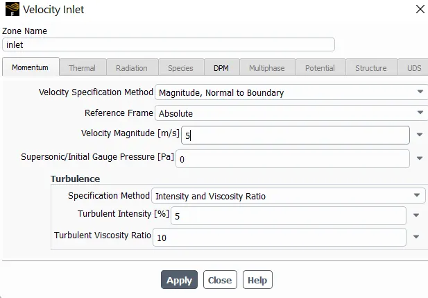
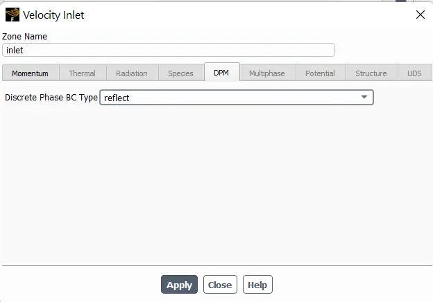
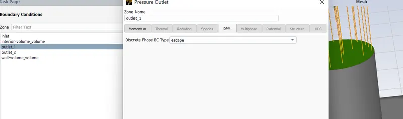
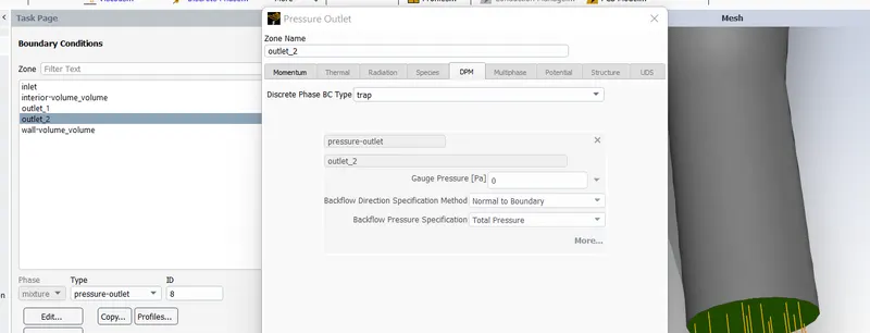
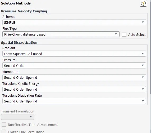
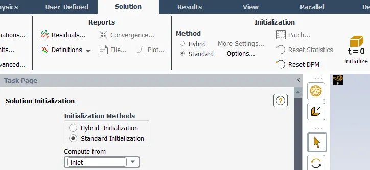
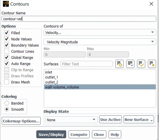
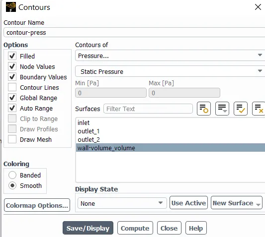
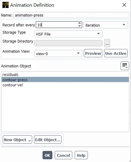
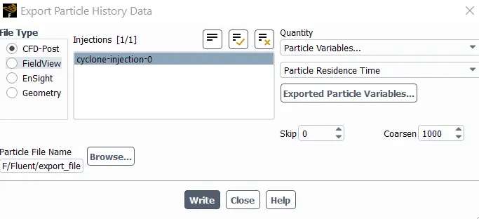
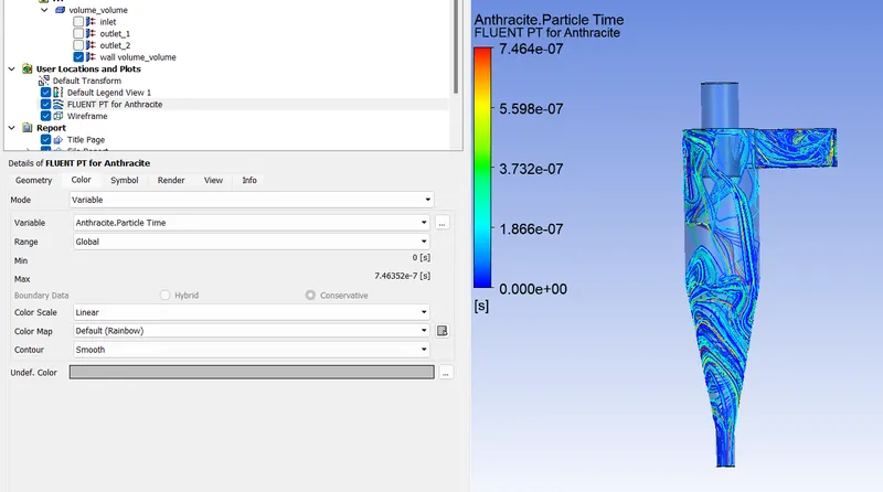
Step 4) Compare the resuts in CFD post
Result
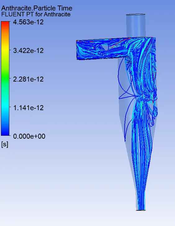
The following resukts were obtained from the attempted challenge:-
| Resut Parameters | 5 μm dia + 5m/s | 5 μm dia + 1m/s |
| Particle Time | 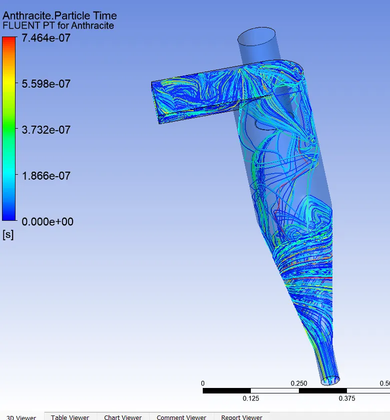 |
 |
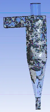
| Vortex | 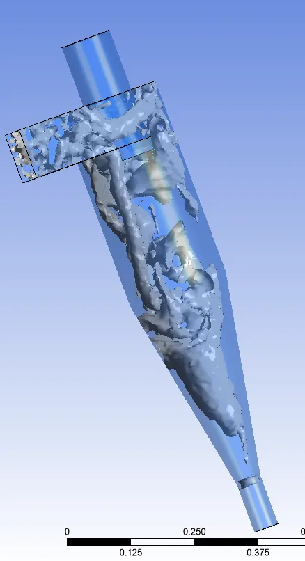 |
 |
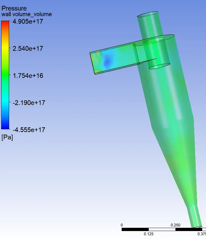
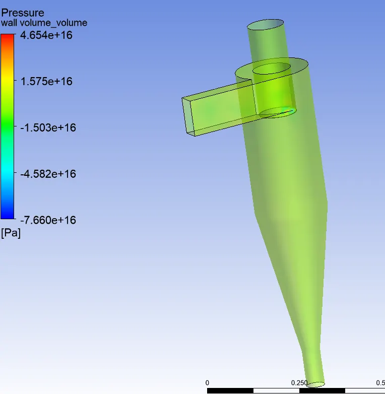
| Pressure drop |
https://drive.google.com/file/d/1QL9tyziQZ8BW555UwtNn_YK-jbG3vX-p/view?usp=sharing |
https://drive.google.com/file/d/1FKD44LI2NPs22qrhsAMDUxszmw2pQ3lv/view?usp=sharing |
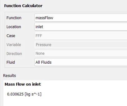
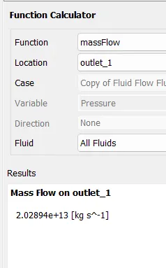
| Mass-Flow | 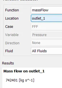 |
 |
| Seperation Efficiency | 1 | 1 |
| Resut Parameters | 5 μm dia + 5m/s | 1 μm dia + 5m/s |
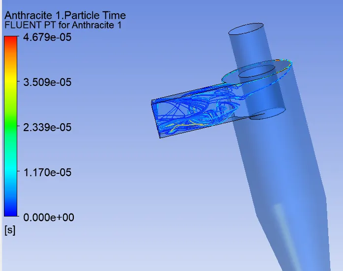
| Particle Time |
https://drive.google.com/file/d/13zEC-vTHSg-7W_YV-EUq7vP99mpLEsMQ/view?usp=sharing |
https://drive.google.com/file/d/1J2cC2AjEs574GmGIDAek0JgX1TOHjLTh/view?usp=sharing |
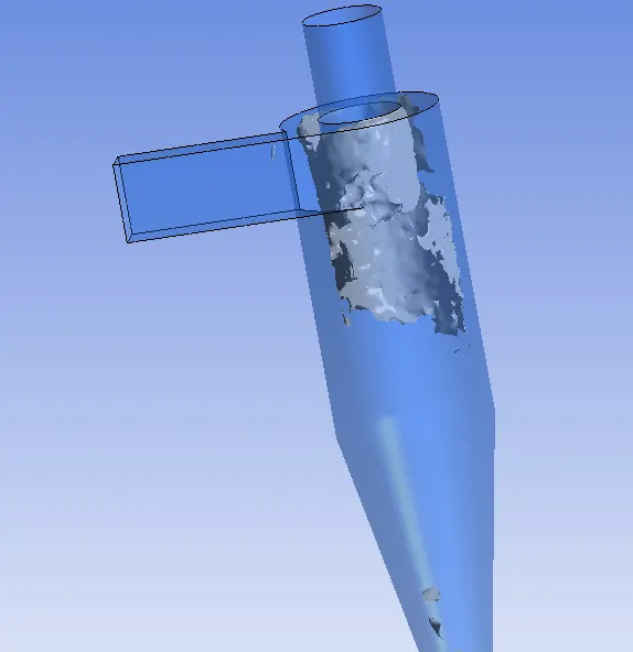
| Vortex | |
 |
| Pressure Drop | 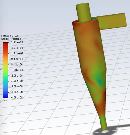 |
 |
| Seperation Efficiency | 1 | 1 |
Conclusion
The following conclusoin can be deduced from our results:-
1. As the velocity (tangential) of same particle size increases, so does the efficiency and P drop also increases due to inertial factor.
2. As the particle size increases with same particle velocity, so does the efficiency and P drop also increases