Week 8 - Simulating Cyclone separator with Discrete Phase Modelling
AIM
To perform analysis on cyclone separator
- And calculate the separation efficiency and pressure drop.
- By varying the particle diameter from 1 μm to 5 μm and calculate the separation efficiency in each case keeping both the particle's and flow velocity as 3 m/s.
- By varying the particle velocity from 1 m/sec to 5 m/sec and calculate the separation efficiency and pressure drop in each case keeping particle diameter size as 5 μm for all cases & keep flow velocity same as particle velocity.
INTRODUCTION
Cyclone seperators are devices that employ a centrifugal force generated by a spinning gas stream to separate particles from the carrier gas. Their simple design, low capital cost and nearly maintenance-free operation make them ideal for use as precleaners for more expensive final control devices such as electrostatic precipitators, etc. Cyclone collection efficiencies can reach 99% for particles bigger than 5 µm, and can be operated at very high dust loading.
We are generally interested in two parameters in order to carry out an assessment of the design and performance of a cyclone which are the collection/seperation efficiency of particles and the pressure drop through the cyclone.
1. Four empirical models used to calculate the cyclone separator efficiency are
- Iozia and Leith Model - It is a model which is developed based on the force balance. The model assumes that a particle carried by the vortex endures the influence of two forces: a centrifugal force, Z and a flow resistance, W. The collection efficiency ηi of particle diameter dpi can be calculated from ηi =1/[1 + (dpc/dpi)]^β where
β is an expression for slope parameter derived based on the statistical analysis of experimental data of a cyclone with D = 0.25 m given as β = 0.62 - 0.87 ln(dpc/100) + 5.21 ln(ab/D2) + 1.05 [ln(ab/D2)]^2 - Li and Wang Model - This model includes particle bounce or re-entrainment and turbulent diffusion at the cyclone wall. A two dimensional analytical expression of particle distribution in the cyclone is obtained. Li and Wang model was developed based on the following assumptions:
• The radial particle velocity and the radial concentration profile are not constant for uncollected particles within the cyclone.
• Boundary conditions with the consideration of turbulent diffusion coefficient and particle bounce re-entrainment on the cyclone wall are: c = c0, at θ = 0. The expression of the collection efficiency for particle of any size is given as
ηi = 1 − exp{−λθ1} where θ1 = 2π(S + L)/a, λ =(1 − α)K*ww/Dr*(rw)^n - Koch and Licht - This collection theory recognized the inherently turbulent nature of cyclones and the distribution of gas residence times within the cyclone. Koch and Licht described particle motion in the entry and collection regions with the additional following assumptions:
• The tangential velocity of a particle is equal to the tangential velocity of the gas flow, i.e. there is no slip in the
tangential direction between the particle and the gas.
• The tangential velocity is related to the radius of cyclone by: u Rn = constant.
A force balance and an equation on the particles collection yields the grade efficiency ηi
ηi = 1 − exp{−2[Gτi Q(n + 1)/D3]^0.5/(n+1)} where
G = 8Kc/Ka^2*Kb^2, n = 1 − {1 −[(12D)^0.14/2.5]}{T + 460/530}^0.3, τi =ρp*dpi^2/18µ. G is a factor related to the configuration of the cyclone, n is related to the vortex and τ is the relaxation term. - Lapple Model - This model was developed based on force balance without considering the flow resistance. Lapple assumed that a particle entering the cyclone is evenly distributed across the inlet opening. The particle that travels from inlet half width to the wall in the cyclone is collected with 50% efficiency. The semi empirical relationship developed by Lapple to calculate a 50% cut diameter, dpc, is dpc = [9 µb/2π Nevi(ρp − ρg)]^1/2 where Ne is the number of revolutions Ne = 1/a[h + (H − h/2)]. The efficiency of collection of any size of particle is given by
ηi =1/[1 + (dpc/dpi)]^2
MESHING AND SOLVING APPROACH
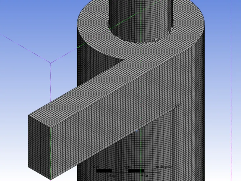
Since the default mesh generates only 4 particles of carrier gas at the inlet, we use Structured mesh of 5 mm which enables more number of gas particles at the inlet.
 |
The finite volume method has been used to discretize the partial differential equations of the model using the SIMPLE method for pressure-velocity coupling and the Second Order Upwind scheme to interpolate the variables on the surface of
the control volume. The RNG k-epsilon turbulence model was used since it is best suited for swirling flows and also overestimates the magnitude of the tangential velocity and the cyclone pressure drop. Also for the simulation using RNG k-epsilon model the steady state solver is sufficient to reach the convergence.To calculate the trajectories of particles in the flow, the discrete phase model (DPM) was used to track individual particles through the continuum fluid.
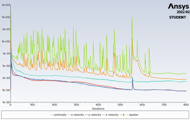
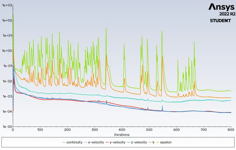
Standard initialization(computed from inlet) was employed for all the cases and were run for 800 iterations each.Boundary conditions were kept fixed for all the cases -
Inlet & wall- Reflect
Outlet1(top) - Escape
Outlet2(Bottom)-Trap
For case 1: Inlet velocity of both the fluid and the injected particle is fixed i.e 3m/s and diameter of the particle ranged from 1 to 5 mircons
For case 2: Inlet velocity of both fluid and the injected particle are varied from 1 to 5 m/s with diameter of 5 microns remaining constant and analysed in 4 cases.
RESULTS
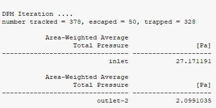
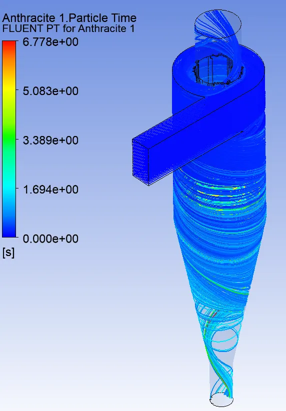
Case 1 - Particle diameter = 1 microns, particle and flow velocity = 3 m/s
 |
 |
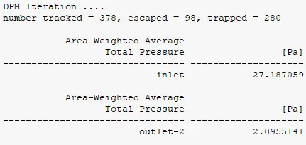
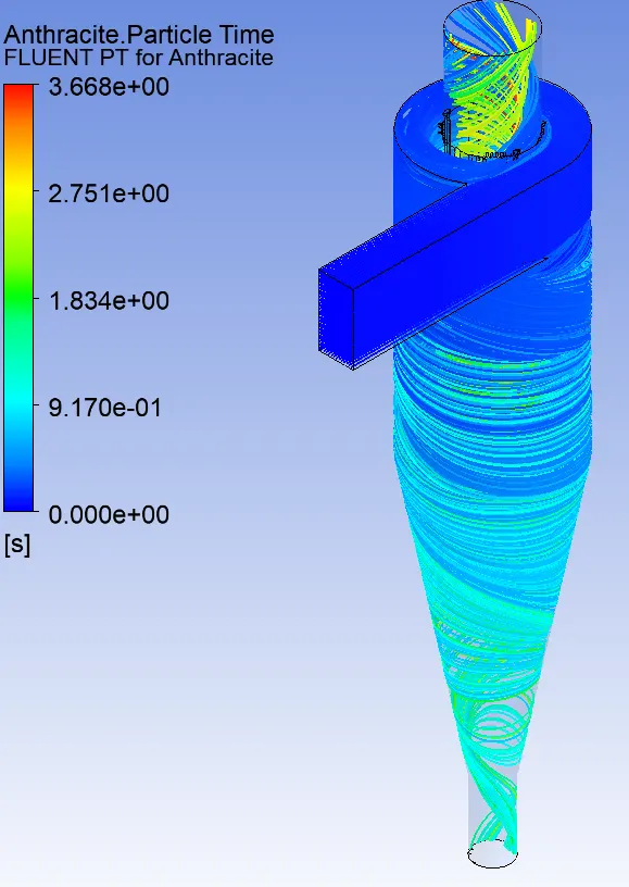
Case 2 - Particle diameter = 5 microns, particle and flow velocity = 3 m/s
 |
 |
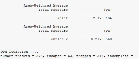
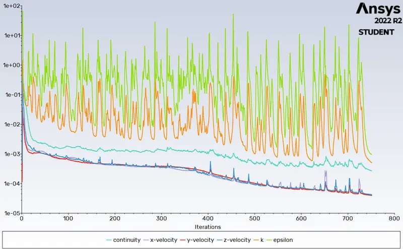
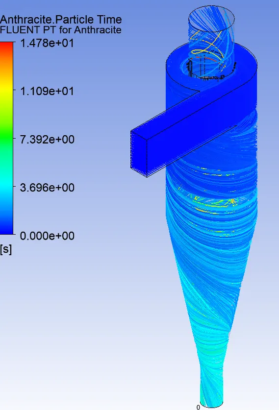
Case 3 - Particle diameter = 5 microns, particle and flow velocity = 1 m/s
 |
 |
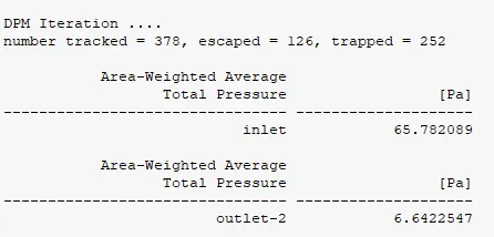
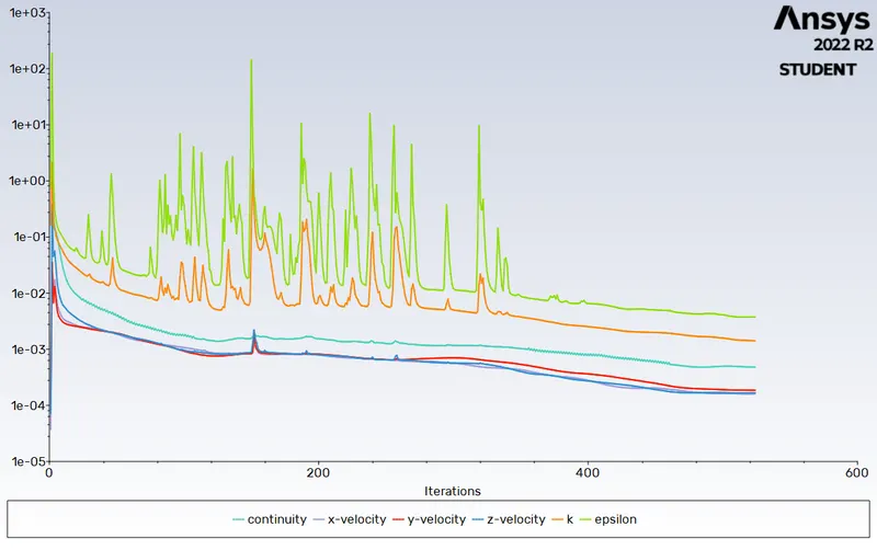
Case 4 - Particle diameter = 5 microns, particle and flow velocity = 5 m/s
 |
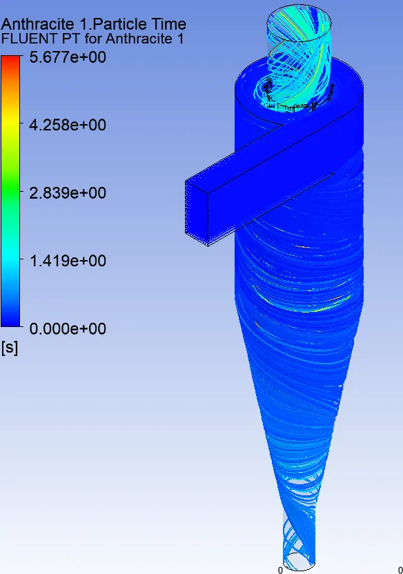 |
CONCLUSION
From the above results table and plots, following conclusions can be drawn -
- By increasing the particle diameter from 1 micrometer to 5 micrometer, the cyclone collection efficiency decreases gradually for constant velocity of 3 m/s.
- By increasing the particle and flow velocity from 1 m/s to 5m/s, the cyclone collection efficiency decreases gradually for constant diameter of 5 micrometer.
- By increasing the particle and flow velocity from 1 m/s to 5m/s, the pressure drop increases gradually for constant diameter of 5 micrometer.