Week 8 - Simulating Cyclone separator with Discrete Phase Modelling
- Simulating Cyclone separator with Discrete Phase Modelling
-
Aim:- To perform analysis on cyclone separator and calculate the separation efficiency and pressure drop.
Objective:-
- To write a few words about any four empirical models used to calculate the cyclone separator efficiency.
- To perform an analysis on a given cyclone separator model by varying the particle diameter from 1 μm to 5 μm and calculate the separation efficiency in each case. Discuss the results. [Use both the velocity's as 3m/sec.]
- To perform an analysis on a given cyclone separator model by varying the particle velocity from 1 m/sec to 5 m/sec and calculate the separation efficiency and pressure drop in each case. Discuss the results. [Use particle diameter size as 5 μm for all cases & keep flow velocity same as particle velocity]
Boundary Conditions:-
Inlet and wall:- Reflect
Outlet(Top):- Escape
Outlet(Bottom/dustbin) - Trap
- Cyclone separators are devices used to separate solid particles from contaminated gas streams and have long been used in industrial applications such as power generation, gas turbines and chemical processes.
- First, cyclone separators are inexpensive to install and maintain and have the advantage of having no moving parts. This keeps maintenance and operating costs low.
- Second, the removed particles are collected dry for easy disposal. A cyclone separator uses centrifugal force to separate solid particles from a carrier gas hydrocyclone.
- The discrete phase model is a subsection of multiphase flow. Discrete Phase Models (DPM) are used to study particle behavior from a Lagrangian view and a discrete perspective.
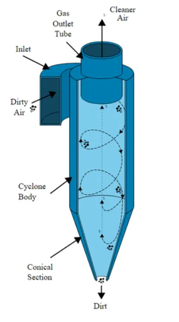
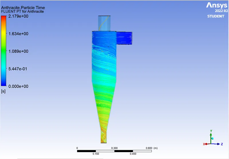
- Cyclone separators work similarly to centrifuges, but with a continuous supply of contaminated air. In the cyclone separator contaminated flue gas is fed into the chamber. The interior of the chamber creates a spiraling vortex resembling a tornado. This swirl and separation is shown in the figure. The lighter component of this gas has lower inertia, making it more susceptible to vortices and allowing them to rise. In contrast, larger particulate matter has more inertia and is less susceptible to eddies.
- Four empirical models were used to calculate the cyclone separator efficiency:
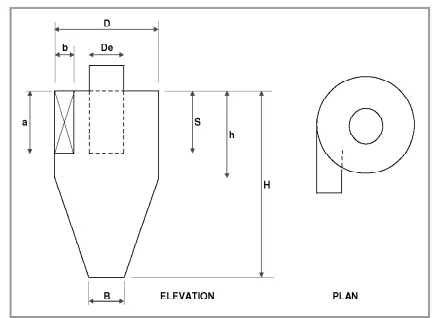
- 1. IOZIA AND LEITH MODEL
- The Iozia and Leith (1990) logistic model is a modified version of the Barth (1956) model developed based on the
force balance. This model assumes that the particles carried by the vortex are subject to his two forces, the centrifugal force
Z and the drag force W. core length zc and core diameter dc ,, are given as
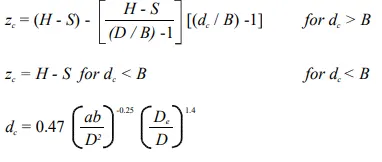
Iozia and Leith's addition to Barth's (1956) original model is an expression for the core length zc and the dip parameter β derived based on statistical analysis of experimental data for a cyclone with D = 0.25 m . dpi can be calculated from the particle size detection degree ηi of,
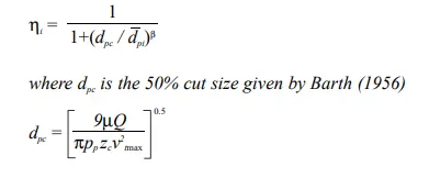
- 2. LI AND WANG MODEL
- The model of Li and Wang (1989) includes particle bouncing or re-entrainment on the cyclone wall and turbulent diffusion. A two-dimensional analysis plot of the particle distribution inside the cyclone is obtained. The Li and Wang model was developed based on the following assumptions:
• Radial particle velocity and radial concentration profiles are not constant for uncollected particles in the cyclone.
• Boundary conditions that account for turbulent diffusion coefficients and particles bouncing off the cyclone walls are:
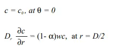
The tangential velocity is related to the radius of the cyclone by:
uRn"> uR^n = constant.
The concentration distribution in a cyclone is given as:
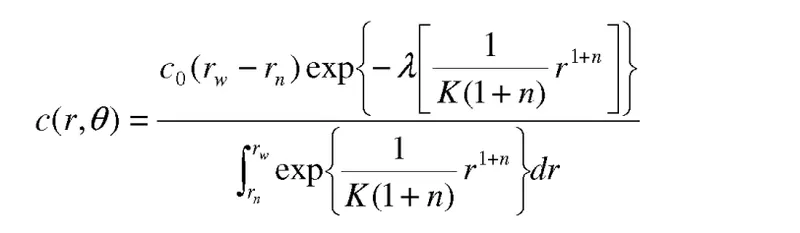
where
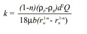
and
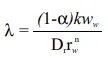
- 3. KOCH AND LICHT MODEL
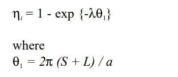
The collection theory of Koch and Licht (1977) recognized the intrinsic turbulent nature of cyclones and the distribution of gas residence times within the cyclones. Koch and Licht use the following additional assumptions to describe particle motion in the inlet and collection regions. and gas.
• Tangential velocity is related to cyclone radius by
uR^n= constant.
The force balance and particle accumulation equations give the efficiency ηi.
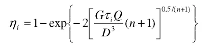
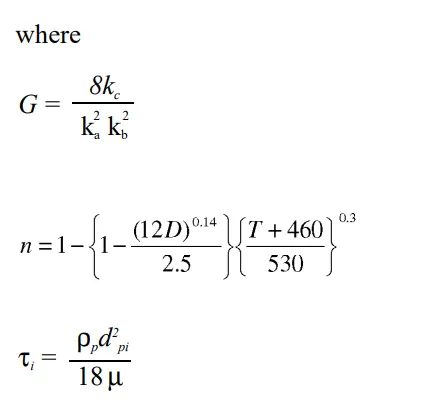 G is a factor related to the configuration of the cyclone, n is related to the vortex and τ">τ is the relaxation term.
- 4. LAPPLE MODEL
The model of Rapple (1951) was developed based on force balance without considering drag. Rapple assumed that his
particles entering the cyclone would be evenly distributed across the inlet ports. Particles moving from the half-width of the inlet to his
wall within the cyclone are collected with 50% efficiency. The semi-empirical relation developed by Rapple (1951) to calculate his 50% cut diameter dpc is
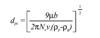
where ,Ne">Ne is the number of revolutions
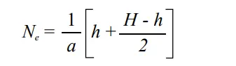
The efficiency of collection of any size of the particle is given by
- Cyclone separation efficiency depends on density, particle size, and cyclone design. Cyclone efficiency generally increases with increasing particle size and/or density. cyclone body length; cyclone gas rotation speed; ratio of cyclone body diameter to gas outlet diameter. dust contamination at the inlet; smoothness of the inner wall of the cyclone.
Similarly, cyclone efficiency decreases as parameters such as gas viscosity increase. diameter of the cyclone body; diameter of the gas outlet; area of the gas inlet channel; gas density; Cyclone separator efficiency depends on the pressure drop across the separator. This is an indirect measure of the energy required to move the gas through the system. Pressure drop is a function of inlet velocity and cyclone diameter. From the discussion above, it is clear that small cyclones are more efficient than large cyclones. However, small cyclones have high pressure drop and limit volumetric flow. Another option is to place smaller cyclones in series and/or parallel to significantly improve efficiency with lower pressure drop. However, these benefits are somewhat offset by increased costs and maintenance issues. Also, these types of arrangements are easy to connect. Using a typical hopper in such an arrangement can lead to re-entrainment problems due to differences in flow rates through the cyclone.
- Procedure
- ANALYSIS
- Changing particle diameter from 1 micrometer to 5 micrometers, with a velocity of 3 m/s:
1. Geometry setup:
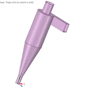
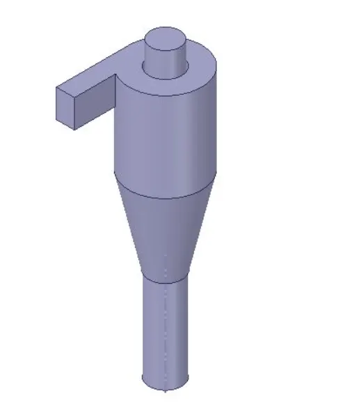
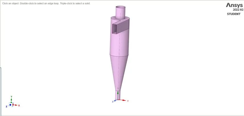
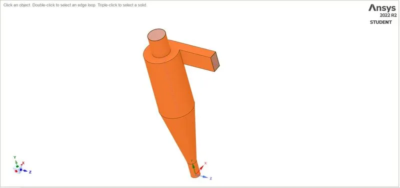
- Volume Extraction
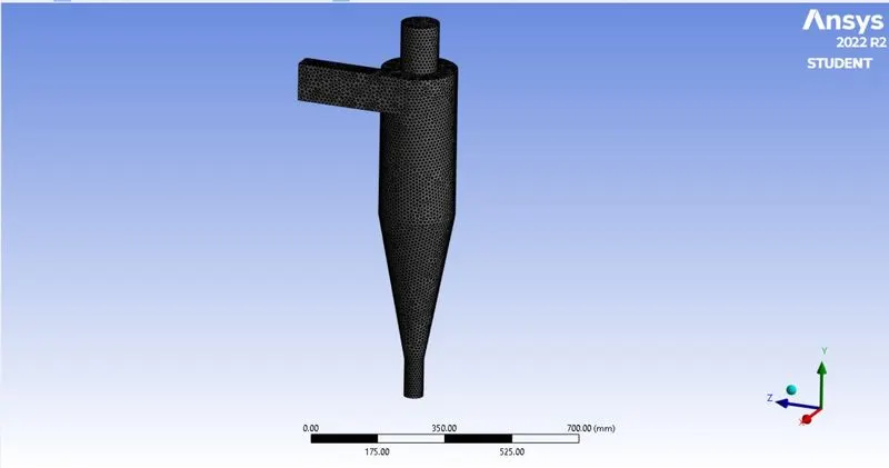
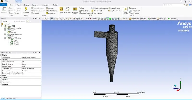
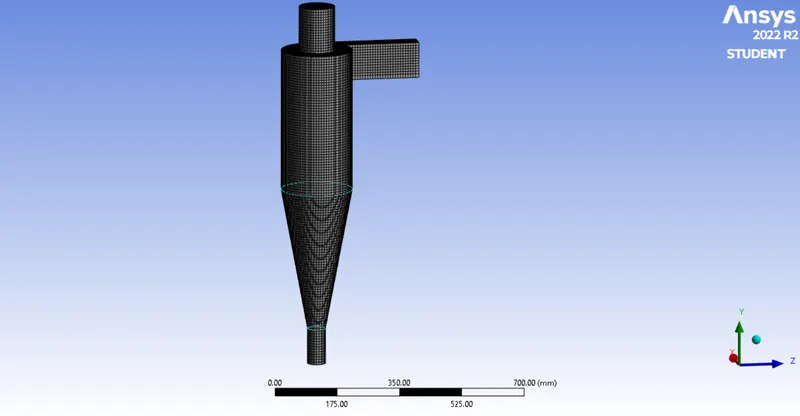
- Meshing
- Element size = 10 mm
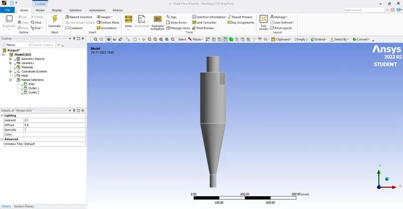
- Name selection
- Results
-
CASE 1
Analysis 1
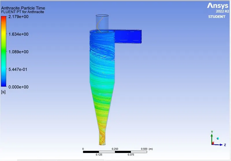
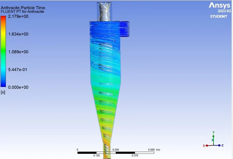
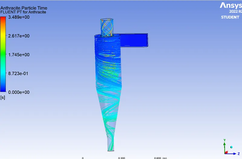
v=3m/s and particle diameter is 5μm.
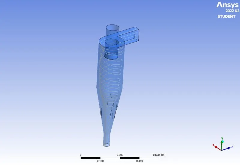
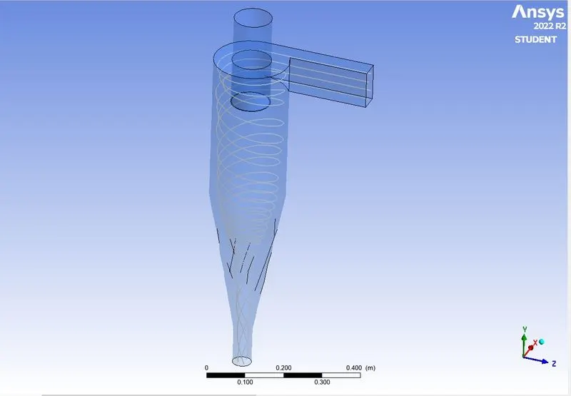
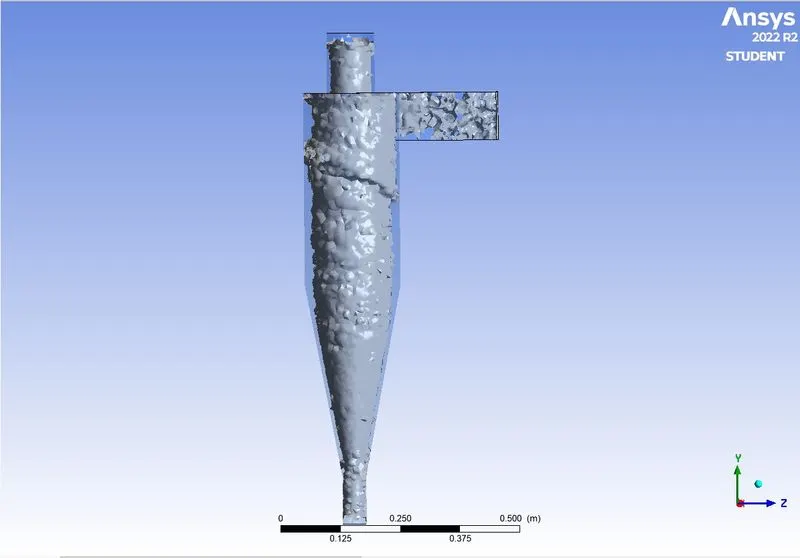
- Anthracite particle time
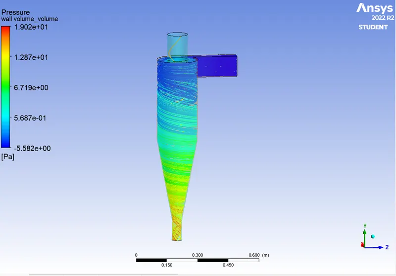
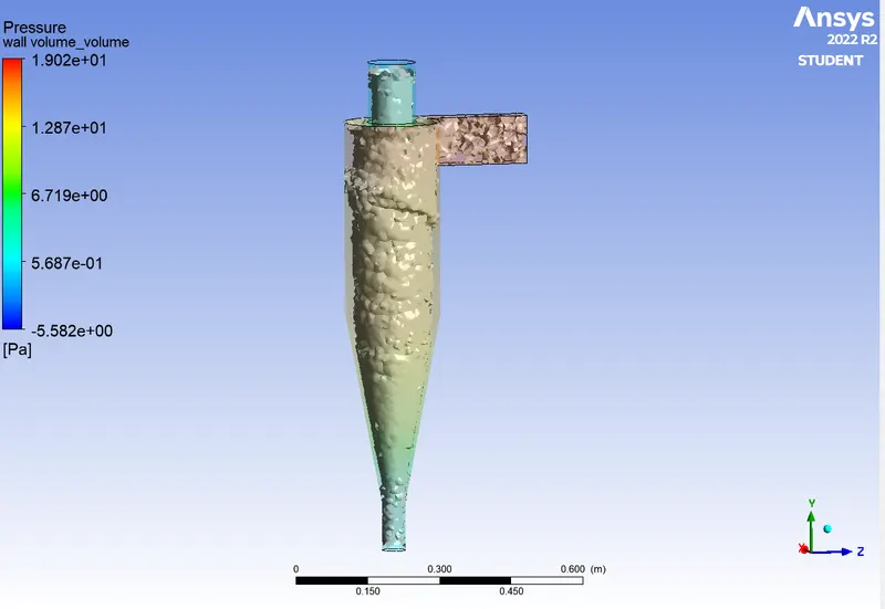
- Pressure
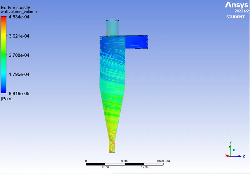
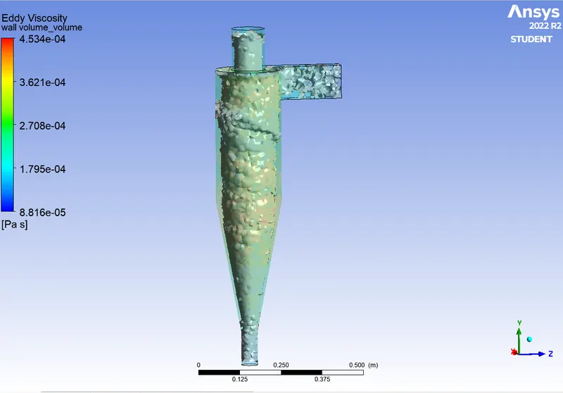
- Eddy viscosity
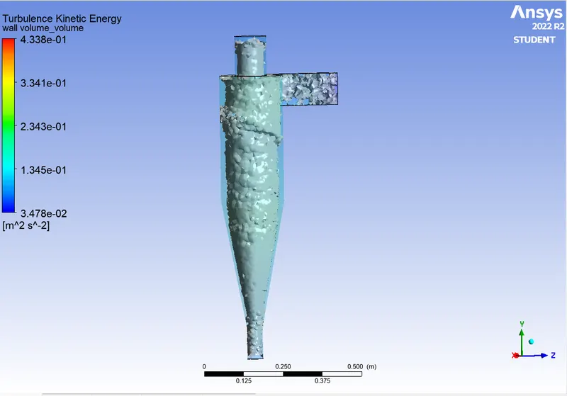
- Turbulent kinetic energy
- Residual plot
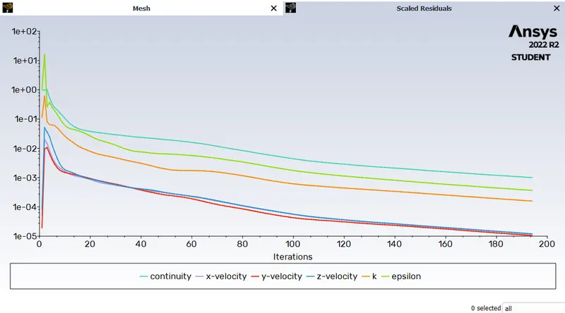
- No. of iterations = 1000
- Mass flow Rate
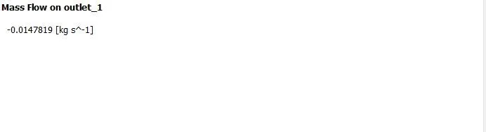
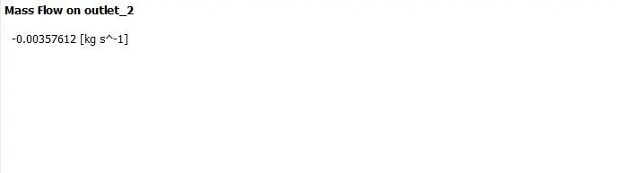
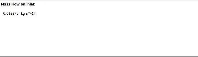
- From the results obtained, we examine the separation efficiency and pressure drop.
Separation Efficiency: Defined as the percentage of particles of a given size that are collected in a cyclone compared to particles of a given size that enter the cyclone. It has been empirically shown that the separation efficiency of cyclone separators increases with increasing average particle diameter and density. Increases the tangential velocity of the gas. decrease in cyclone diameter; increase in cyclone length; extraction of gas along with solids from the cyclone legs. In this case, depending on the particle history data, separation efficiency is defined as the ratio of the concentration removed from the feed stream to the initial concentration of the feed stream. In this case, the ratio of the number of particles trapped to the total number of particles tracked applies.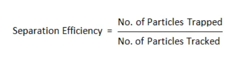 = 44/ 91 = 0.483
Pressure Drop: In cyclone separators the pressure drop across the cyclone is very important. Pressure drop has a significant impact on cyclone performance parameters. The total cyclone pressure drop is due to cyclone inlet and outlet losses, as well as frictional and kinetic energy losses. Turbulence and energy dissipation usually create the greatest pressure drop in the body. Pressure drop is defined as the total pressure difference between two points in a fluid-carrying network. - Analysis case 2
- v=3m/s and particle diameter is 1μm

- Analysis case 3
- v=3m/s and particle diameter is 3μm

- Here,the fluid velocity and particle velocity are 3m/sec for all particle sizes varied in Case-1. Therefore the pressure drop remains constant for all analyses of case-1.
- Animation link
-
CASE 2
In this analysis, velocity is varied from 1 to 5 m/s while particle diameter is kept as 5μm
- For velocity = 1m/s
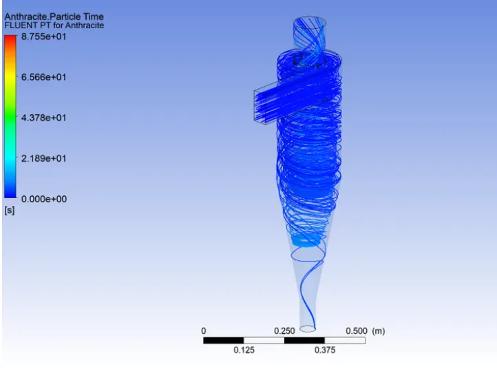
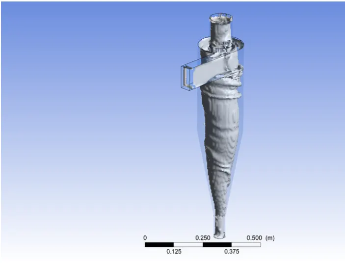
-
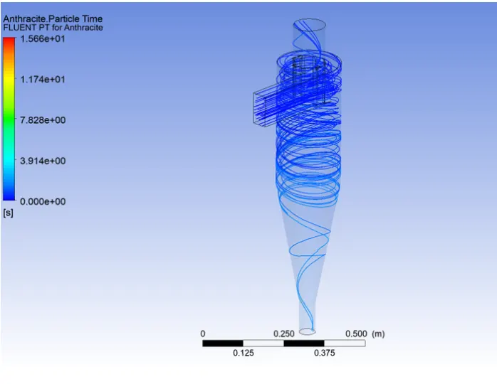
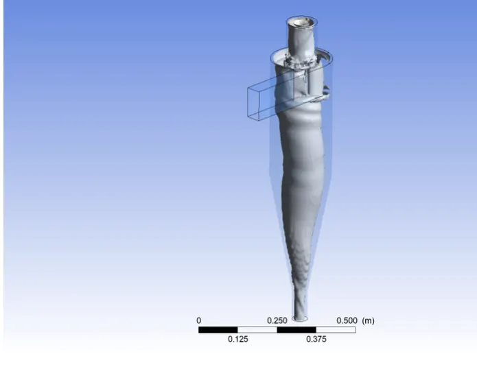
At 2 m/s:
Flow contour and vortex:
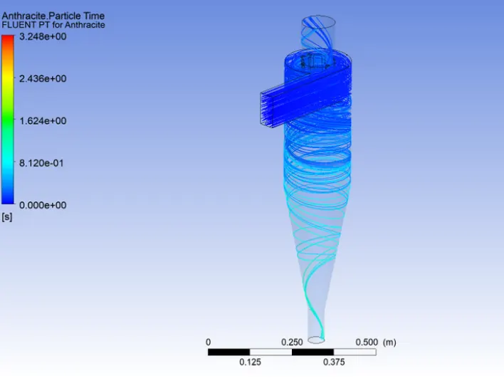
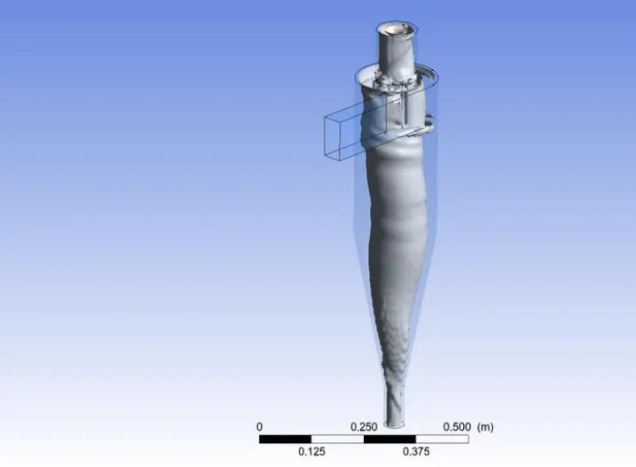
- At 5 m/s:
Flow contour and vortex:
-
For varying velocities at 5 micrometres:
Velocities (m/s) Particles Tracked Particles Escaped Particles Trapped Particles incomplete Pressure drop
ΔP)
Separation
Efficiency(η)
1 m/s 190 59 10 121 2.22 14.49
2 m/s 190 46 26 118 9.64 36.11
5 m/s 190 37 152 1 60.9 80.49
- Stepwise Explaination
- Geometry Settings:
a. Select the fluid flow module and start editing geometry.
b. Import the model step file into Spaceclaim.
c. A liquid volume is extracted from the geometry using the prepare option. So that you can analyze the liquid flow in the cyclone separator.
d. Since we are only interested in the fluid flow and not the outer surface, we suppress the physics by hiding the previous geometry. - Face selection tool is selected. Entry, exit (top) and exit (bottom) are named. Particles enter through the inlet, light contaminants are expelled at the top, and heavy contaminants are captured at the bottom. Since we are in the x-y plane, we need to turn on gravity. Since gravitational acceleration acts upward, it is assigned a g value of -9.81 on the positive y-axis.
- A pressure-based solver is used. A steady-state analysis is performed and the velocity formulation is limit and absolutely vertical.
- Physics Setup: Turbulence Modeling: A K-ε (2-equation) model with RNG and vortex dominated flow is selected. The wall modeling functions are standard wall functions.
- Viscosity model setup
- DPM
model can interact with the continuous phase. The DPM interval level is 10. Particle types are inert to injection. Anthracite is selected from a fluid database. It is emitted from the inlet with a velocity of 3 m/s in the x direction. This speed can be further manipulated. The particle size chosen for the first analysis is 1 micron. Vary the particle size from 1 micron to 5 microns and calculate the resolution. DPM Settings - Boundary Conditions:
Boundary conditions are provided for three named choices: entrance, exit (1) above, and exit (2). under.
For the inlet, the momentum condition is a velocity of 3 m/s in the x direction, absolute and perpendicular to the boundary. - It is set to reflect DPM conditions. This means that no particles should escape or become trapped in the inlet.
- For the top outlet, the Momentum condition is the Pressure condition and the DPM condition is set to Escape. Particles can escape from this boundary
- The bottom exit is also the pressure exit, trapping the DPM condition.
- Here we specify various DPM conditions such as reflect, escape and trap before all the boundary conditions.
- Reflections: Particles that bounce off the boundary of the problem with a change in momentum defined by the coefficient of restitution.
- Escaped: Particles are reported as 'escaped' when they reach the relevant boundary. The calculated trajectory ends.
- Trap: The calculated trajectory is terminated and the particle's fate is recorded as "trapped".
- For an evaporating droplet, its entire mass instantly goes into the gas phase and enters the cell near the boundary. Particle combustion passes the remaining volatile mass to the vapor phase. Gradients are based on least-squares cells. Pressure, momentum, turbulent kinetic energy, and turbulent dissipation rate are quadratic downwind.
- Parametric Study
Post-processing: Export data from Fluent to CFD post to visualize results. - Contour plots are obtained for particle time, Eddy viscosity, swirl, pressure and Turbulent Kinetic Energy.
- Conclusion
- From the pressure-velocity diagram above, we can conclude that the pressure is higher near the wall region forming the outer vortex.
- A feature that creates a low pressure area in the middle of the cyclone separator due to the high pressure near the wall, where the lighter particles escape to the upper outlet and the heavier particles are collected in the lower outlet.
- Particle size, density and cyclone design,Cyclone efficiency is generally determined by particle size, density, inlet duct velocity, cyclone body length, gas rotation speed within the cyclone, ratio of cyclone body diameter to gas outlet diameter, inlet dust load, cyclone inner wall increases with increasing smoothness.
- The efficiency of the cyclone decreases as parameters such as gas viscosity, cyclone body diameter, gas outlet diameter, gas inlet duct area, gas density and air leakage to the dust outlet increase.
- Efficiency increases as penetration velocity or particle size increases. The recovery efficiency of the
Cyclone Separator depends on the pressure drop across the cyclone. Here, pressure drop is an indirect measure of the energy required for a gas to move particles. - Pressure drop depends on inlet air velocity and particle size. The results show that the heavier particles are trapped at the bottom outlet and the lighter particles escape through outlet 1.
- Pressure drop = Total inlet pressure - Total Outlet Pressure
- However, we also find that due to the interaction between light and heavy particles, the light particles are also confined to the lower outlet and there is an exchange of inertial forces between them.
- As a result, there is a transfer of kinetic energy from heavy particles to heavy particles. As a result, a certain number of heavy particles can be observed leaking out of the upper outlet.