Week 8 - Simulating Cyclone separator with Discrete Phase Modelling
Aim:- To perform analysis on cyclone separator and calculate the separation efficiency and pressure drop.
Objective:-
- To write a few words about any four empirical models used to calculate the cyclone separator efficiency.
- To perform an analysis on a given cyclone separator model by varying the particle diameter from 1 μm to 5 μm and calculate the separation efficiency in each case. Discuss the results. [Use both the velocity's as 3m/sec.]
- To perform an analysis on a given cyclone separator model by varying the particle velocity from 1 m/sec to 5 m/sec and calculate the separation efficiency and pressure drop in each case. Discuss the results. [Use particle diameter size as 5 μm for all cases & keep flow velocity same as particle velocity]
Boundary Conditions:-
Inlet and wall:- Reflect
Outlet(Top):- Escape
Outlet(Bottom/dustbin) - Trap
Note:
Structural mesh gives the best results, so you can use cutcell meshing approach available in Ansys Meshing.
Theory:-
removed Components from Cyclone Separators:
- Dust
- Particles: Abrasive, Corrosive, Adhesive, Explosive
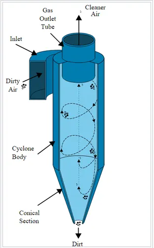
Diagram:
Process Description:
- Working Principle:
- Cyclone is a centrifugal separator in which particles, due to their mass, are pushed to their outer edges as a result of centrifugal force. Incoming Air is automatically forced to adopt a fast revolving spiral movement – the so called double vertex. This double spiral movement consists of an outer stream, which flows downwards in spiral and inner stream, which flows upwards in spiral. At the interchange between both streams, air passes from one stream to another. The particles which are present in the air re forced to the outer edges and leave the separator via collection device fitted to the bottom of the separator.
- Air speed of the cyclone lies between 10 to 20 m/s, and the most common speed is 16 m/s. If there are fluctuations in speeds (with lower speeds), separation yield falls quite drastically.
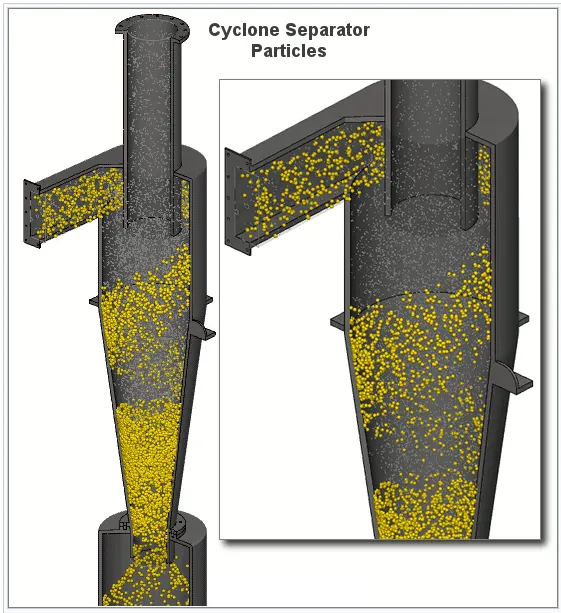
- Most cyclones are built to control and remove particulate matter that is larger than 10 micrometers in diameter. However, there do exist high-efficiency cyclones that are designed to be effective on particles as small as 2.5 micrometers. As well, these separators are not effective on extremely large particulate matter. For particulates around 200 micrometers in size, gravity settling chambers or momentum separators are a better option.
- Out of all of the particulate-control devices, cyclone separators are among the least expensive. They are often used as a pre-treatment before the flue gas enters more effective pollution control devices. Therefore, cyclone separators can be seen as "rough separators" before the flue gas reaches the ne filtration stages.
Discrete Phase Modeling:
- It is employed when there are solid Particles in Gas, or Liquid or Lquid Droplets in Gas , or Bubbles in Liquid.
There are two ways to carry out DPM
- Un-coupled Flow
- Coupled Flow
Uncoupled Flow:
- In this type of flow, Discrete Phase will not have any interaction with Continuous Phase.
Coupled Flow:
- It will influence the flow of Continuous Phase.
Cases too study:-
| Mesh length | Partical Size | Velocity |
| 10 | 1 | 3 |
| 10 | 3 | 3 |
| 10 | 5 | 3 |
| 10 | 5 | 1 |
| 10 | 5 | 5 |
| 7 | 5 | 5 |
| 5 | 5 | 5 |
CFD Work Flow:- CFD codes are structured around the numerical algorithms that can tackle fluid flow problems. In order to provide easy access to their solving power all commercial CFD packages include sophisticated user interfaces to input problem parameters and to examine the results
Its threee step process
(i) a pre-processor
involves defination of geometry, grid generation, selection of phenomenon that need to model
(ii) a solver
intergration of governing equation, discretisation and solution
(iii) a post-processor
ploting of contour, graphs and making movies.
In solving fluid flow problems we need to be aware that the underlyingphysics is complex and the results generated by a CFD code are at best asgood as the physics (and chemistry) embedded in it and at worst as good asits operator with CFD
Solving and Modeling Approch:-
There are no way present to understand and analyse the effeciveness of the mixiing tee model.
1. analytical approch
2. simulation approch
3. experimental approch
using analytical approch and experimental approch is time consuming and high cost senario. this could be eliminated by using simulation approch in which we can analyse the system with the actual codition we are intrested in.
To do this we are using ansys fluent solver
we are using fluid flow analysis using Fluent solver because we are interested in the total effectiveness of the fluid in the mechnical tee model, here we are using two different models to analyse the effectiveness of the mixing of fluid.
Approch we are using.
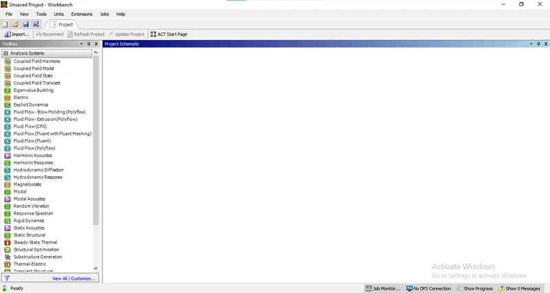
1. We need to open Ansys workbench
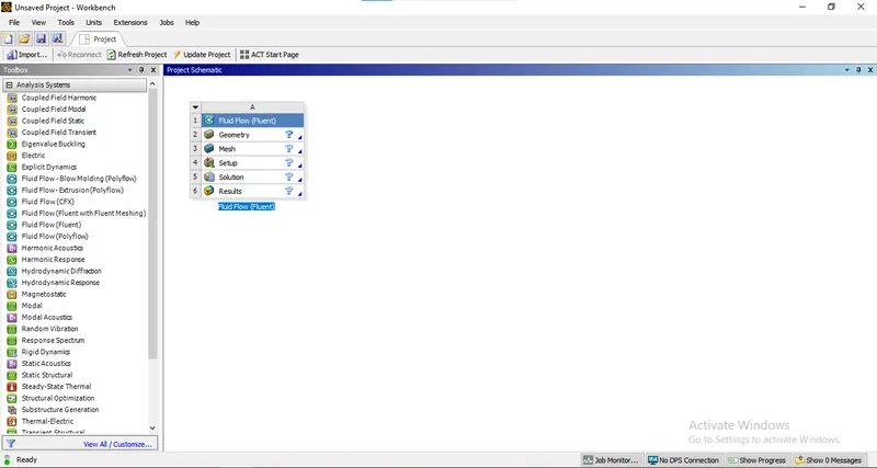
2. Choose the Appropiate Solver
3. Assign Appropiate name
4. Choose geometry and select new spaceclaim model.
5. Load the appropiate file
6. Implement the geometrical operation
7. Apply the mesh and provide name selection
8. Choose setup, select the appropiate model
9. Initalisation and running the simulation
10. Result making i.e. countour plots graphs
1. Opening Ansys workbench
2. Choose the Appropiate Solver
3. Assign Appropiate name
4.Opening of space claim geometry do to geometrical operation
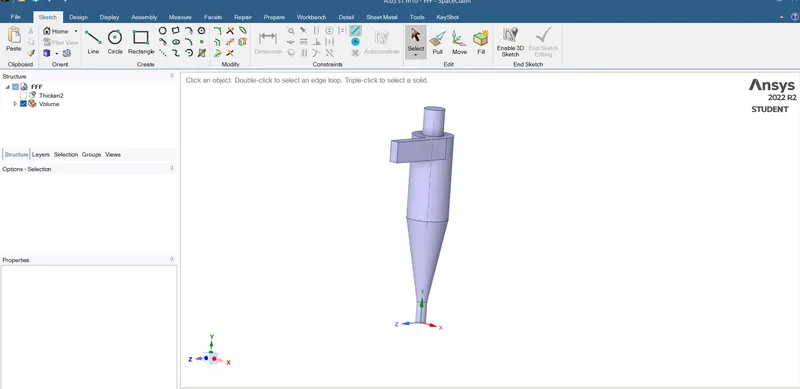
final geometry after extracting volume and suppress the outer body for physics
we done with geopetry part now we can move towards mesh mode.
5. Meshing
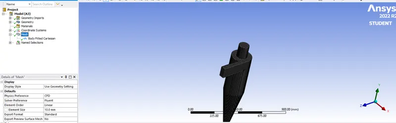
here we are using cartesian mesh, which is a structure mesh and cyclone seprator is a simple geometry
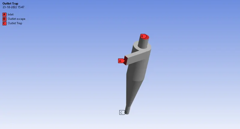
Setup
1. enable gravity
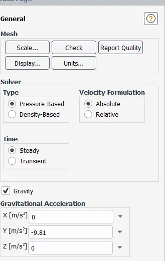
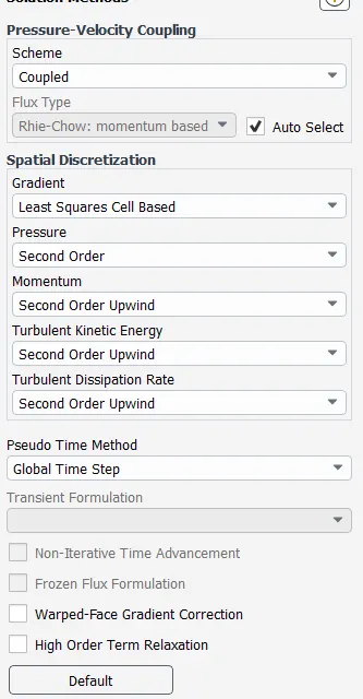
Choose method
Choosing model
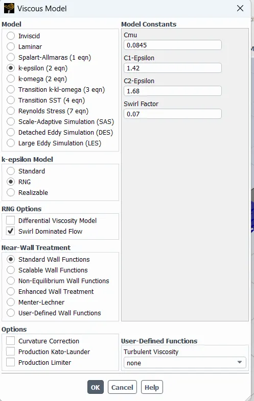
rng and reliazable model give very accurate result when flow is swirl dominationg
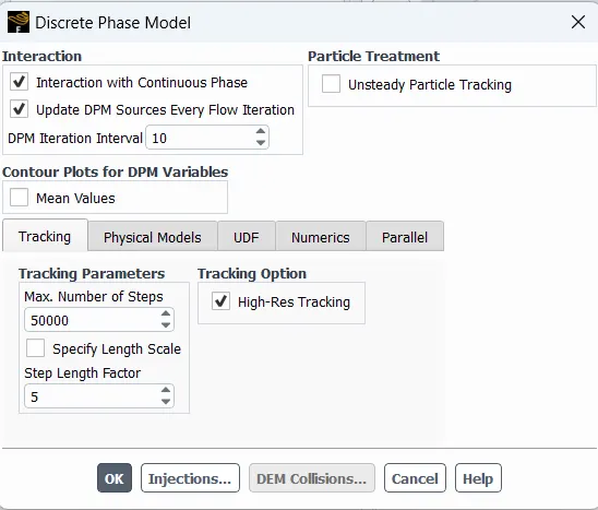
Enabling descret model
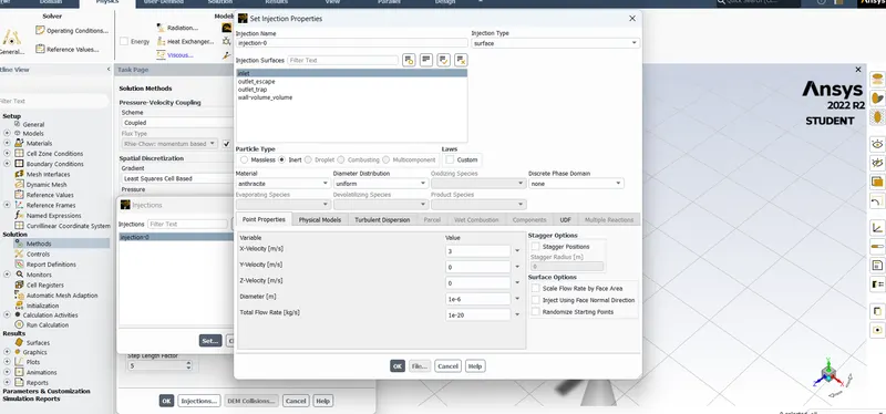
set the injection here
Apply boundary condition
1. inlet
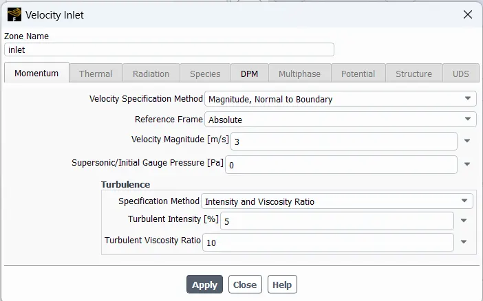
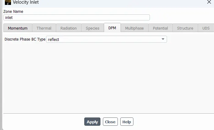
in similar manner we can apply
2. escape as escape
3. trap as trap
4. wall as reflect
initialiization
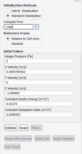
Now we can run the program
Choose iteration as 350
Result:-
| Sr No. | Mesh length | Size | velocity | iteration | conversed | tracked | escape | trap | eff |
| 1 | 10 | 1 | 3 | 350 | 176 | 91 | 29 | 62 | 68% |
| 2 | 10 | 3 | 3 | 350 | 176 | 91 | 28 | 63 | 69% |
| 3 | 10 | 5 | 3 | 350 | 176 | 91 | 34 | 57 | 63% |
| 4 | 10 | 5 | 5 | 350 | 162 | 91 | 33 | 52 | 57% |
| 5 | 10 | 5 | 1 | 350 | Not | 91 | 23 | 68 | 75% |
| 6 | 7 | 5 | 5 | 350 | 183 | 98 | 21 | 77 | 79% |
| 7 | 5 | 5 | 5 | 600 | Not | 378 | 83 | 274 | 72% |
| Mesh length | inlet pt | outlet escape pt | outlet trap pt | difference pt |
| 10 | 22.47 | 3.13 | 2.58 | 19.34 |
| 10 | 22.47 | 3.13 | 2.58 | 19.34 |
| 10 | 22.47 | 3.13 | 2.58 | 19.34 |
| 10 | 64.15 | 9.21 | 7.23 | 54.94 |
| 10 | 2.31 | 0.03 | 0.287 | 2.28 |
| 7 | 79.18 | 11.82 | 7.46 | 67.36 |
| 5 | 91.84 | 12.72 | 7.11 | 79.12 |
Residual Chart
| Sr No. | Residual chart |
| 1 | 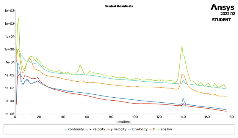 |
| 2 | 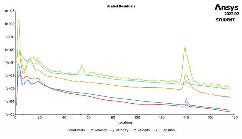 |
| 3 | 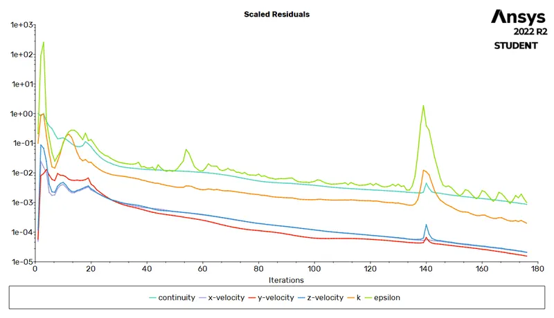 |
| 4 | 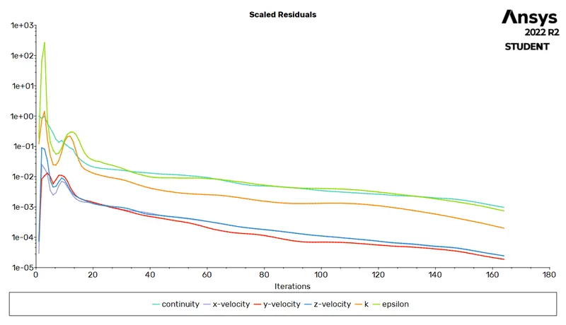 |
| 5 | 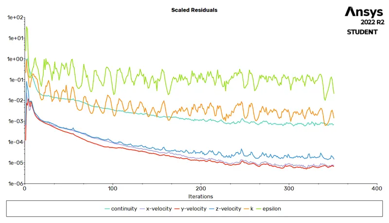 |
| 6 | 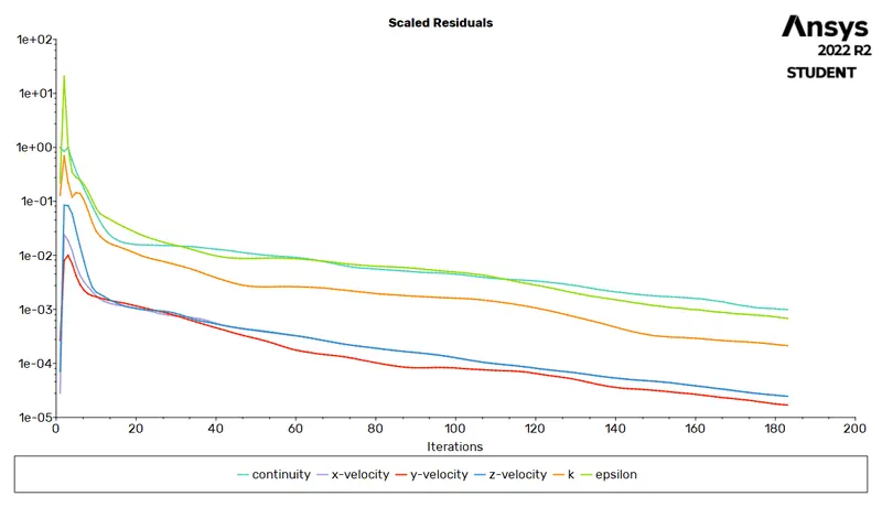 |
| 7 | 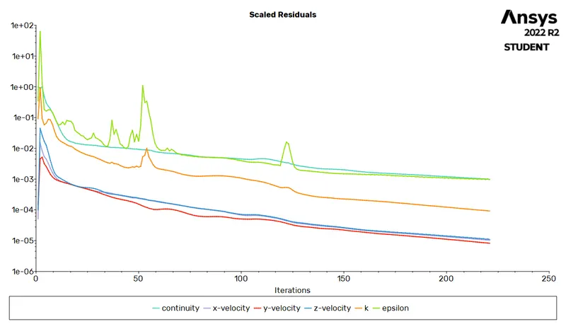 |
Pressure contour
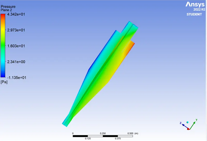
Infrences
1. as the velocity reduces the efficiency of the cyclone seprator increases
2. efficiency of the cyclone seprator depend on the element size
3. finer the mesh finer will be the accuracy of the final result
4. when we use fine mesh we end up with incomplete result
5. maximum efficiency we are getting in this particular experiment is for mesh length 7 particle size 5micro meter and velocity is 5