Week 8 - Simulating Cyclone separator with Discrete Phase Modelling
Notice: - After the analysis, the size of the file is more, but in the challenge submission time it is not supported because of its large so I am sharing the google drive link please download from the link.
Link: https://drive.google.com/file/d/1A19ayHhpXmM2QMXQ0UhCSs6CKIo71TU0/view?usp=sharing
Aim: To perform analysis on the cyclone separator and calculate the separation efficiency and pressure drop.
Objective:
- To write a few words about any four empirical models used to calculate the cyclone separator efficiency.
- To perform an analysis on a given cyclone separator model by varying the particle diameter from 1 μm to 5 μm and calculate the separation efficiency in each case. Discuss the results. [Use both the velocity's as 3m/sec.]
- To perform an analysis on a given cyclone separator model by varying the particle velocity from 1 m/sec to 5 m/sec and calculate the separation efficiency and pressure drop in each case. Discuss the results. [Use particle diameter size as 5 μm for all cases & keep flow velocity same as particle velocity]
Introduction
When separating particles from the carrier gas, cyclones use the centrifugal force created by a rotating gas stream. They are perfect for use as pre-cleaners before more expensive final control systems like bag-30 houses or electrostatic precipitators because of their straightforward design, inexpensive initial investment, and almost maintenance-free operation. Cyclones excel in extreme temperature and pressure environments thanks to their durable construction and flexible component materials.
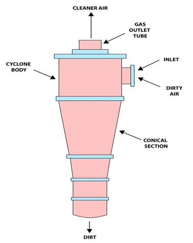
Effectiveness
Cyclone separator is practically use to separate the particulate matter in the fuel gas. This is able to remove 50-99% from the all-particulate matter in the fuel gas. The size of the particles has a significant impact on how effectively the cyclone separators can remove this material. Less of these particles can be sorted out when there is a lot of lighter particulate matter present. Because of this, cyclone separators perform at their best with flue gases that have a lot of large particles matter present.
The cyclone separator has both advantages and disadvantages, in the advantages this apparatus has or moveable parts, not more cost of equipment, easy to install and maintenance also easy. It is moveable from one place to another easily and the removal particle are stored. The disadvantages are less the 10-micrometre particle stored not possible and sticky or tacky materials are difficult for the machines to manage.
Empirical models used to calculate the cyclone separator efficiency
- Iozia and Leith model
this model is developed based on a balance of forces a particle carried by a vortex is said to be subject to two forces: a centrifugal force (Z) and a flow resistance (W). It is possible to determine the collecting effectiveness of particle diameter
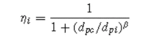
β is an expression for slope parameter

D=0.25
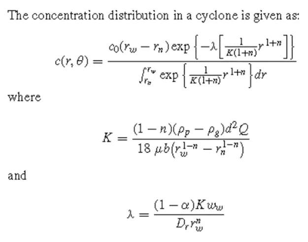
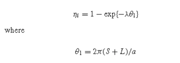
- Li and Wang Model
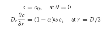
The following presumptions served as the foundation for the Li and Wang model:
- For uncollected particles inside the cyclone, the radial particle velocity and the radial concentration profile are not constant.
- The following boundary conditions are taken into account when considering the turbulent diffusion coefficient and particle bounce re-entrainment on the cyclone wall.
- Koch and Licht Model
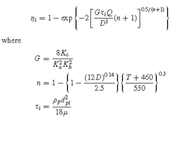
This theory took into account the distribution of gas residence durations within cyclones as well as the fact that cyclones are naturally turbulent. Koch and Licht made the following additional assumptions for describing particle motion in the entry and collecting regions:
- There is no slip in the tangential direction between the particle and the gas because the tangential velocity of a particle is equal to the tangential velocity of the gas flow.
- The radius of the cyclone and the tangential velocity are related by the formula: uR^n = constant.
- Lapple Model
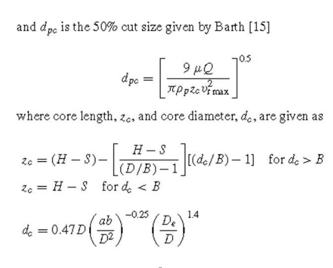
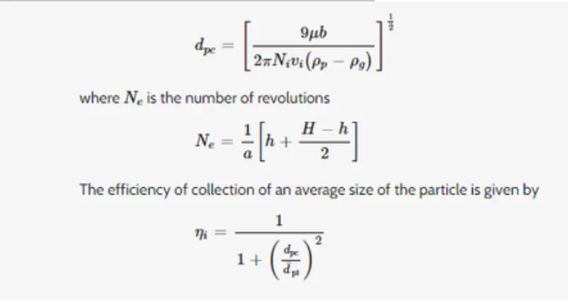
The force balance-based Lapple (1951) model was created without taking the flow resistance into account. Lapple made the supposition that a particle entering the cyclone is dispersed uniformly over the inlet hole. In the cyclone, the particle that moves from the entrance half-width to the wall is gathered with a 50% efficiency. Lapple (1951) created a semi-empirical connection that relates calculate a 50% cut diameter, dpc is
Solving and modelling approach
In the cyclone separator problem for modelling and solving we have to follow some steps
- Geometry setup
- Meshing
- Setup and calculation
- Result
Geometry setup
In the geometry setup, we have to import the model and extract the fluid volume and take that volume for calculation in that volume include with one input and two output.
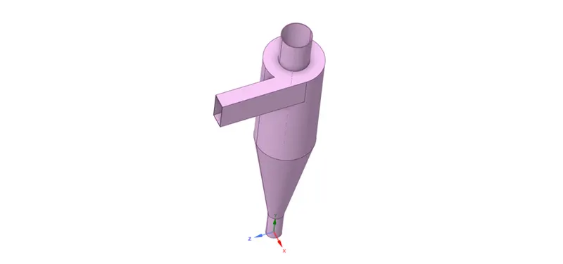
(Cyclone separator model)
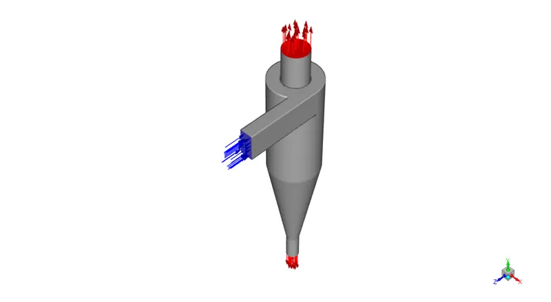
(Geometry after volume extraction)
Meshing
The meshing is done with the element size 5mm with fine mesh, we take this mesh size for all the cases and take the different results. and give the name section one inlet section and two outlet section, upper one as outlet 1 and lower one as outlet 2.
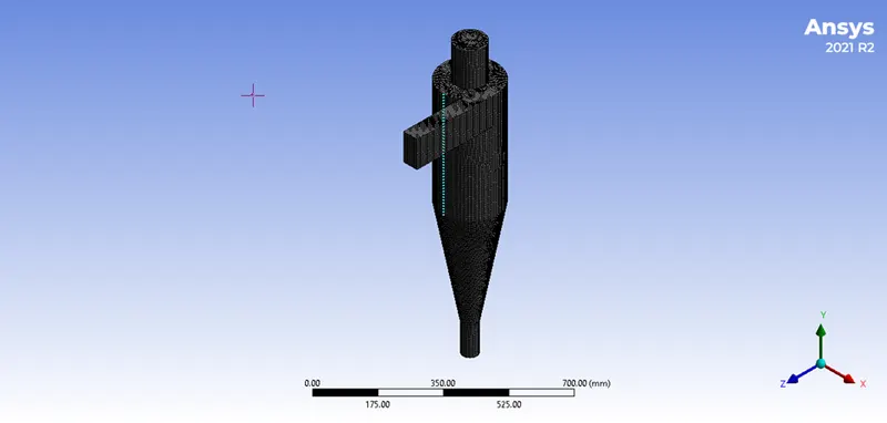
(Meshing of the cyclone separator)
Setup and calculation
In the setup section, we take a pressure-based solver, steady state and give gravitational acceleration in the y direction as -9.81m/s^2. In the method, section takes k-epsilon model.
In the discrete phase model with injection, five different diameter molecules with a single velocity in the first case and in the second case take a single diameter of the molecule with five different velocities.
In the first case with a 3m/s velocity and 1 to 5µm diameter of a molecule. In the second case with a 5µm diameter of a molecule and taking 1 to 5 m/s inlet velocity. In the boundary condition take the inlet velocity as the given velocity in the discrete phase and DPM as reflected, in outlet 1 (Top) pressure outlet and DPM as escape, in outlet 2 (Bottom) take the pressure outlet and DPM as trap. Initialize with standard initialization and calculate with 1000 iterations.
Result
After the setup and calculation, we export the result of the track particle history data file and import it into the CFD post and show the vortex of the anthracite particle which we have taken.
Case-1
In case 1 we take the inlet velocity as 3m/s and five different diameter anthracite particles.
For 1µm diameter
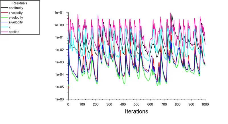
(Scale residual)
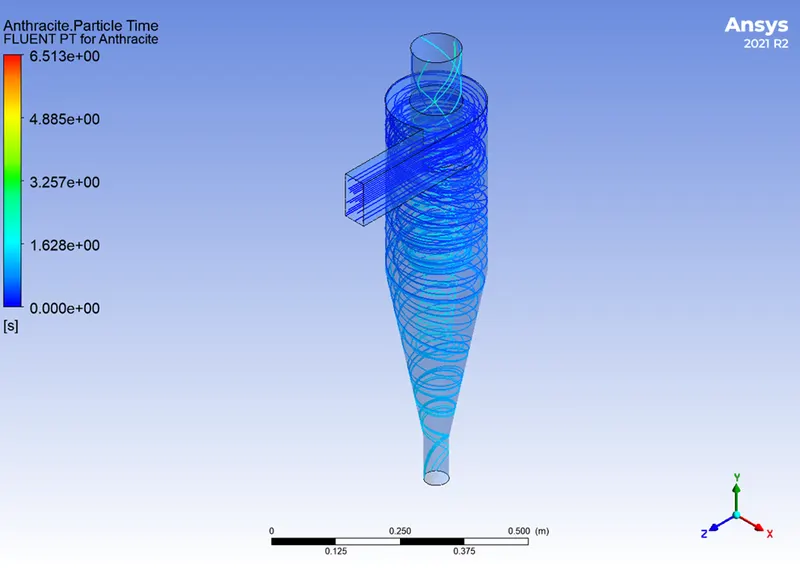
(Anthracite particle tracking)
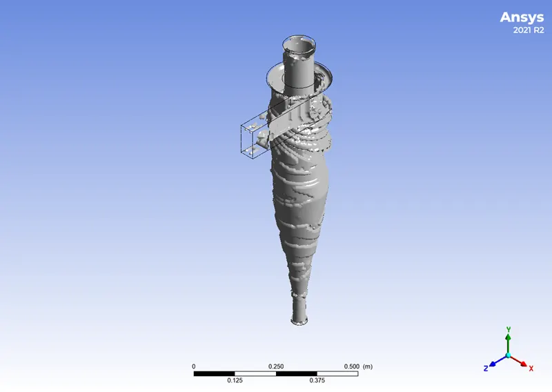
(Vortex of anthracite)
For 2µm diameter
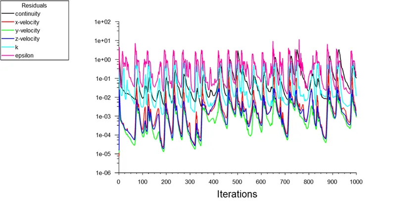
(Scale residual)
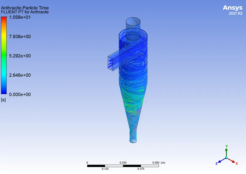
(Anthracite particle tracking)
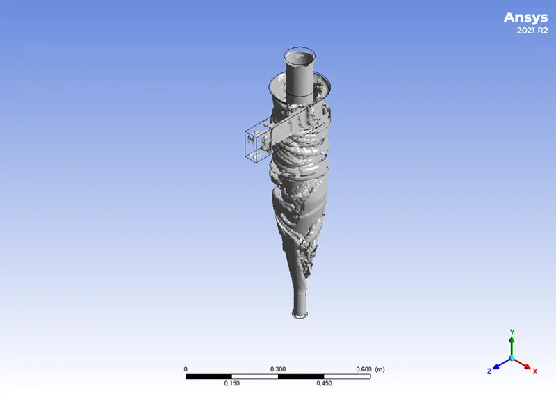
(Vortex of the anthracite particle)
For 3µm diameter
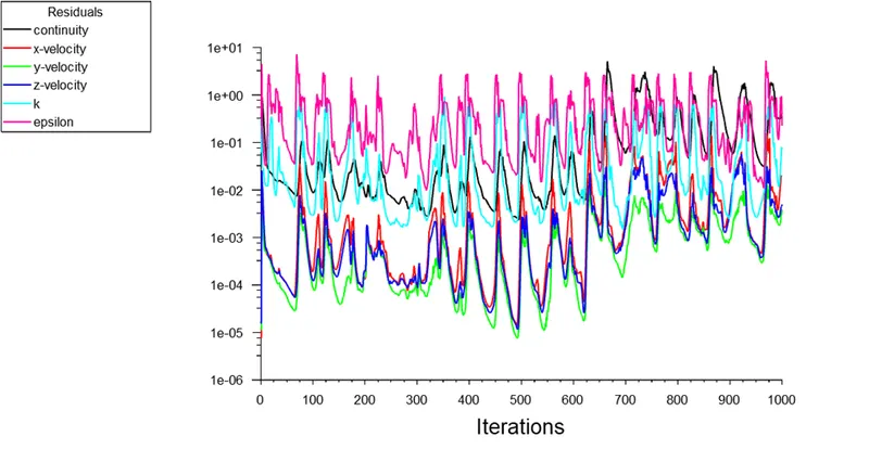
(Scale residual)
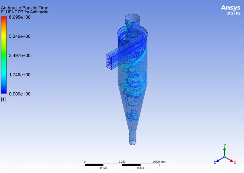
(Anthracite particle tracking)
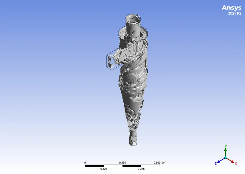
(Vortex of anthracite particle)
For 4µm diameter
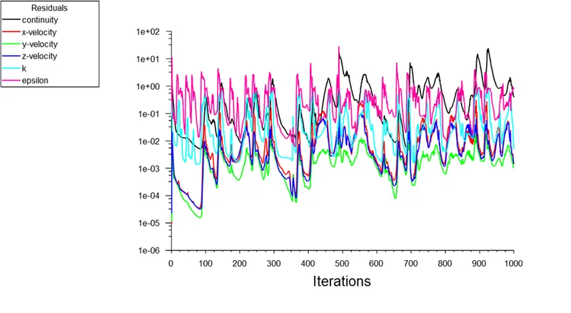
(Scale residual)
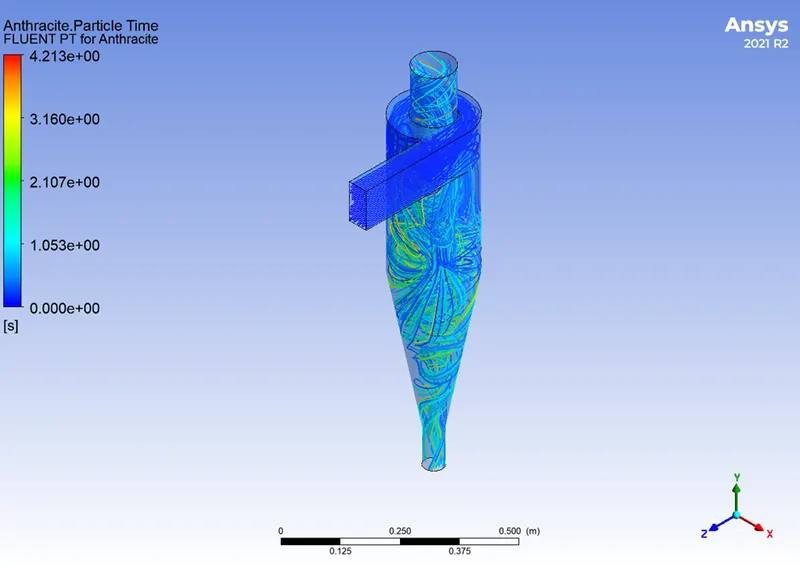
(Anthracite particle tracking)
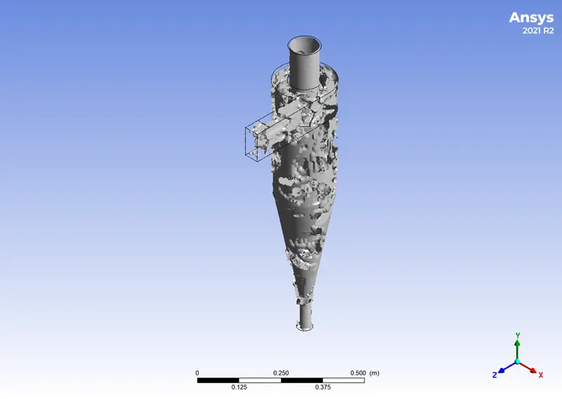
(Vortex of anthracite)
For 5µm diameter
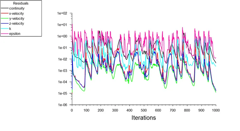
(Scale residual)
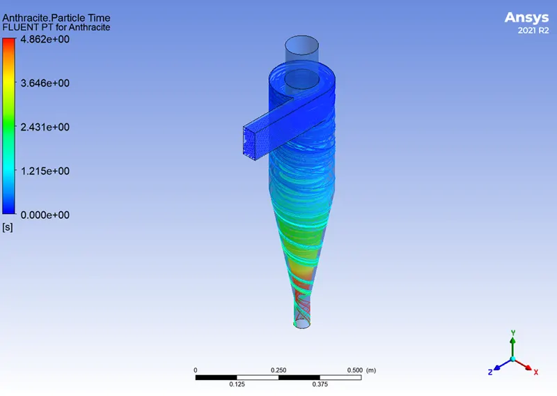
(Anthracite particle tracking)
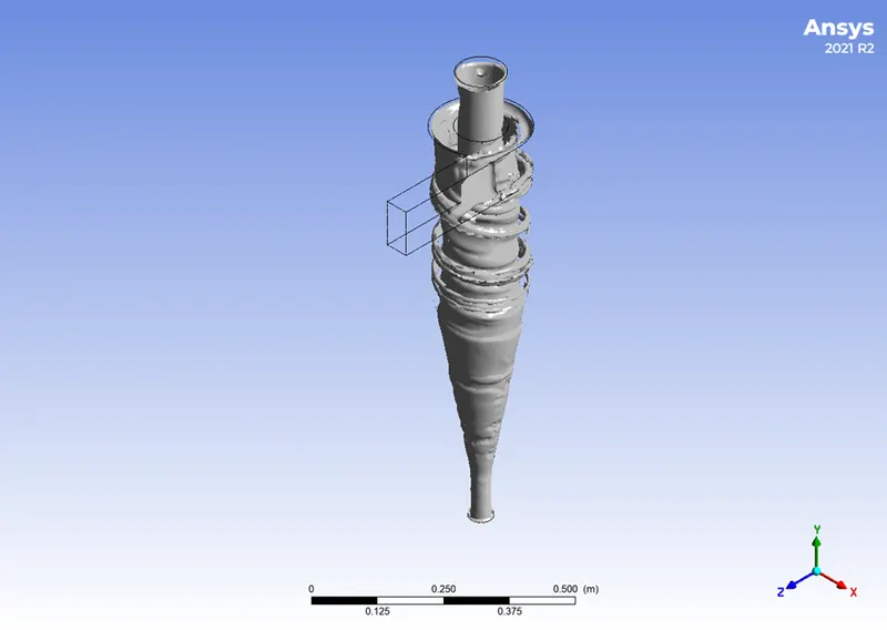
(Vortex of anthracite particle)
Case-2
In the case, 2we take 5µm diameter of a particle and apply 1 to 5 m/s inlet velocity.
For 1m/s inlet velocity
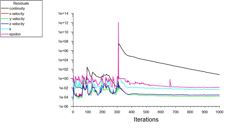
(Scale residual)

(Anthracite particle tracking)
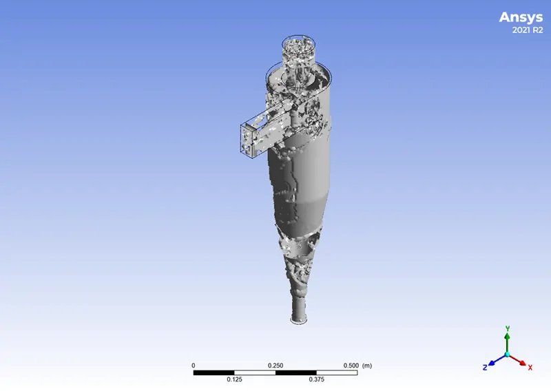
(Vortex of anthracite particle)
For 2m/s inlet velocity
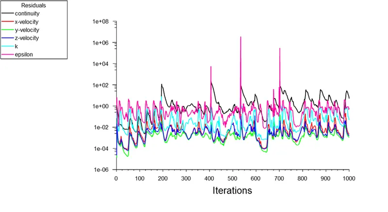
(Scale residual)
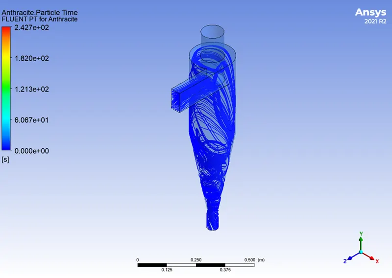
(Anthracite particle tracking)
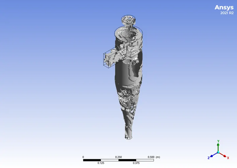
(Vortex of anthracite particle)
For 3m/s velocity
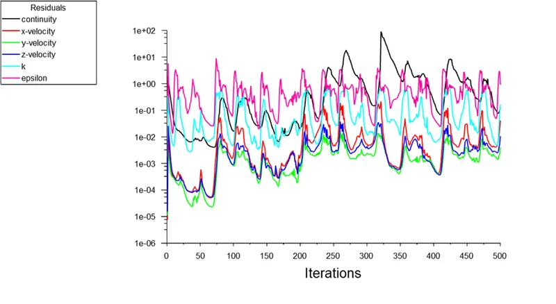
(Scale residual)
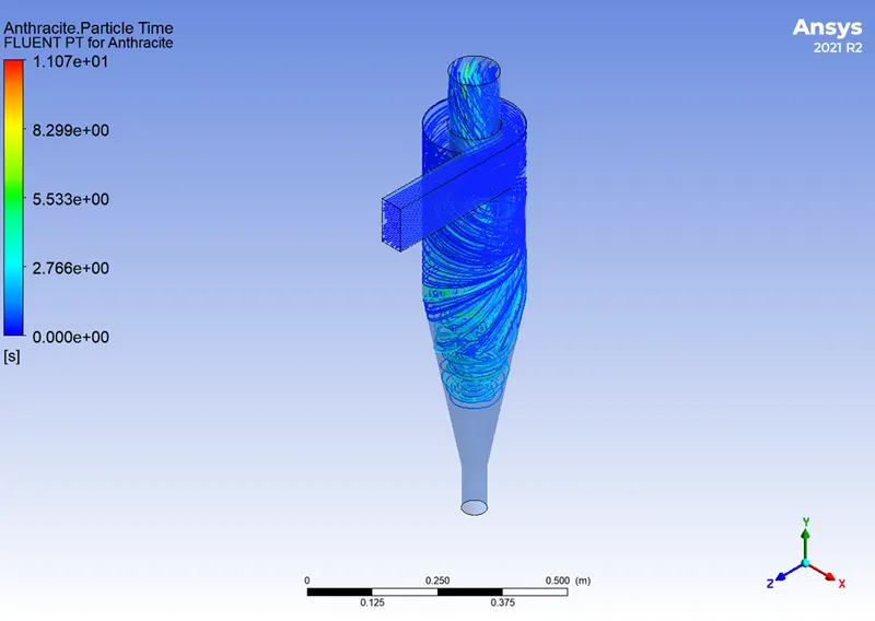
(Anthracite particle tracking)
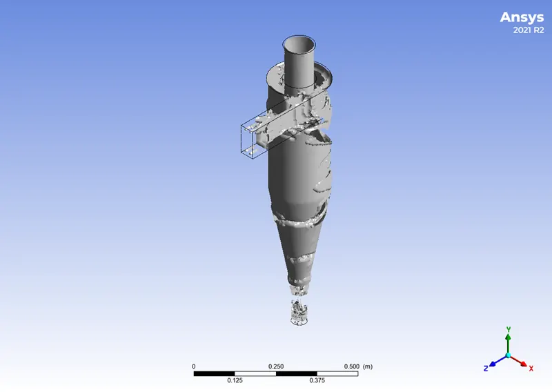
(Vortex of anthracite particle)
For 4m/s inlet velocity
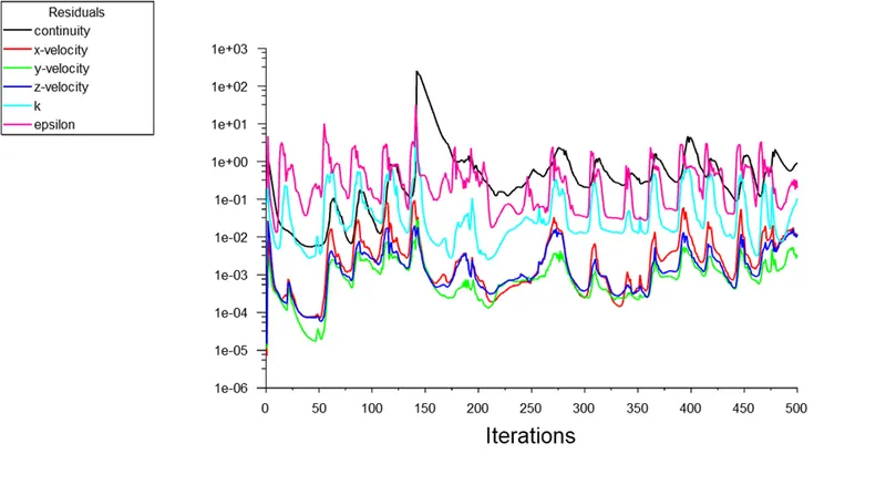
(Scale residual)
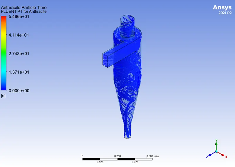
(Anthracite particle tracking)
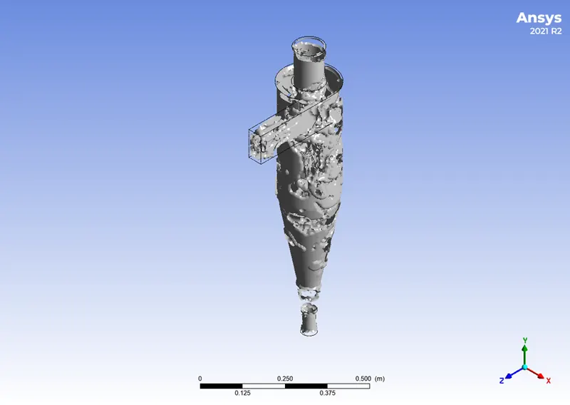
(Vortex of anthracite particle)
For 5m/s inlet velocity
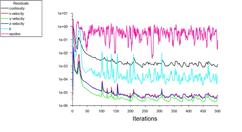
(Scale residual)
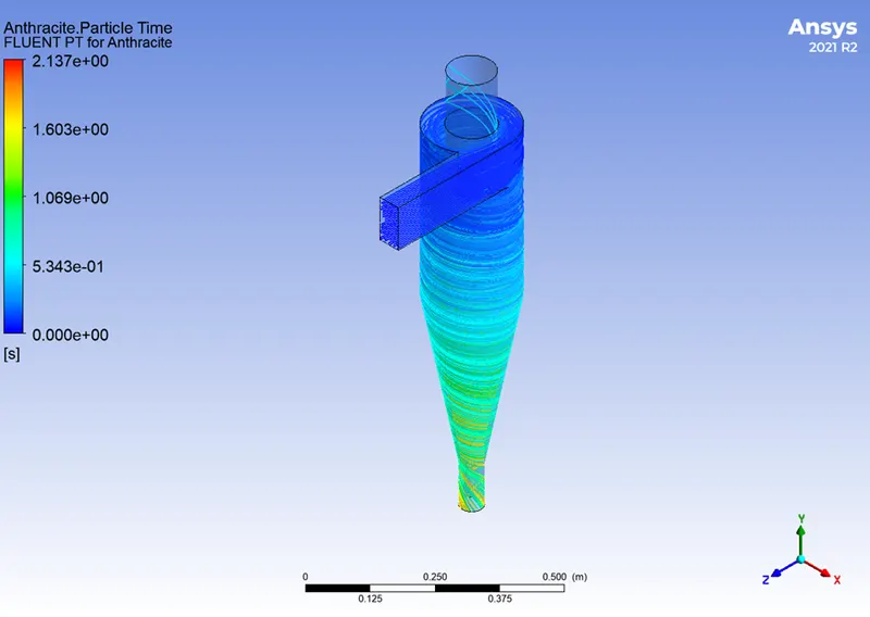
(Anthracite particle tracking)
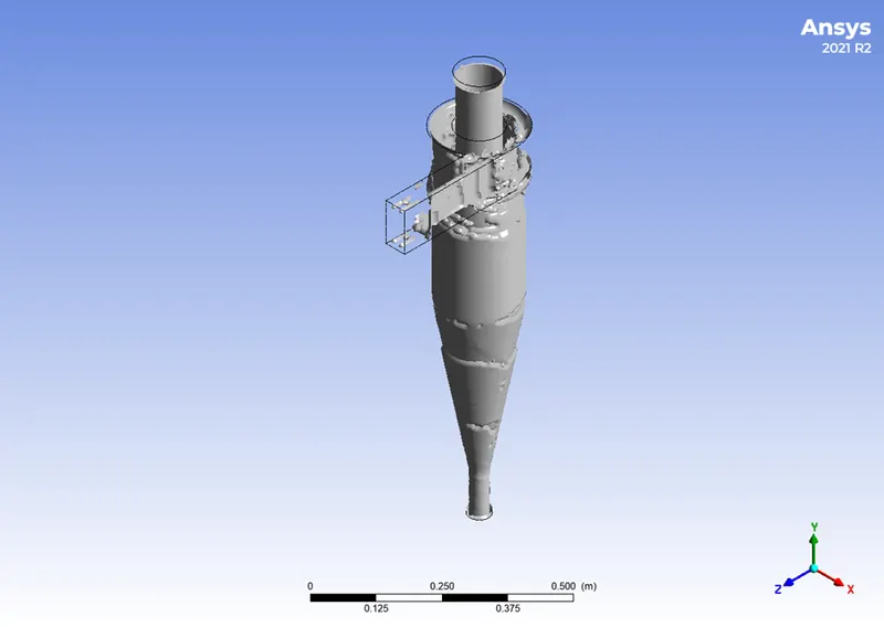
(Vortex of anthracite particle)
Separation efficiency
It is described as the percentage of particles of a particular size that are collected in the cyclone as opposed to those that enter the cyclone. Experience has shown that raising particle mean diameter and density, increasing gas tangential velocity, decreasing cyclone diameter, increasing cyclone length, and extracting gas and solids simultaneously through the cyclone legs all boost the separation efficiency of cyclone separators. The separation efficiency in this instance is defined as the ratio of concentration that has been removed from the feed stream to the initial concentration in the feed stream, depending on the particle history data. The ratio of the tracked particle total to the number of captured particles in this scenario.
Separation efficiency = no. of particles trapped / no. of particles tracked
Pressure drop
In a cyclone separator, the pressure drop throughout the cyclone is crucial. The performance characteristics of a cyclone are substantially impacted by the pressure decrease. The entry and exit losses, friction, and kinetic energy losses within the cyclone all contribute to the overall pressure reduction in the cyclone. The body often experiences the most pressure reduction as a result of whirling and energy loss. The difference in total pressure between two places on a fluid-carrying network is known as pressure drop.
Pressure drop, ΔP = Total inlet pressure - Total Outlet Pressure (escape)
Analysis
Case-1 3m/s inlet velocity with varying particle diameter
|
Sl No |
Particle diameter |
Number of particle track |
Particle escaped |
Particle trapped |
Particle incomplete |
Separation efficiency % |
|
1 |
1e-6 |
200 |
65 |
134 |
1 |
67 |
|
2 |
2e-6 |
200 |
48 |
84 |
68 |
42 |
|
3 |
3e-6 |
200 |
187 |
8 |
5 |
4 |
|
4 |
4e-6 |
200 |
103 |
94 |
3 |
47 |
|
5 |
5e-6 |
200 |
1 |
199 |
0 |
99.5 |
Case-2 5µm particle diameter with varying inlet velocity
|
Velocity m/s |
Particle track |
Particle escaped |
Particle trapped |
Particle incomplete |
Pressure drop |
Separation efficiency % |
|
1 |
200 |
9 |
190 |
1 |
4.11 |
95 |
|
2 |
200 |
14 |
180 |
6 |
12.64 |
90 |
|
3 |
200 |
28 |
169 |
3 |
72.31 |
84.5 |
|
4 |
200 |
56 |
130 |
14 |
80.74 |
65 |
|
5 |
200 |
29 |
171 |
0 |
75.42 |
85.5 |
Conclusion
The two simulations outlined above demonstrate how separation efficiency is influenced by the particles' diameter and velocity. Larger separation effectiveness results from increased diameter and velocity. The influence of velocity is greater than the effect of particle diameter. The rate of pressure loss depends on velocity. When the diameters are different sizes but the velocity is constant, the pressure drop is nearly constant. Higher velocity results in a greater pressure decrease.