Week 2 Challenge : Surface meshing on a Pressure valve
Aim: -
Finding the valve model’s error and observing the mesh quality with different mesh lengths using ANSA.
Procedure: -
Use of TOPO module
After importing the model of the valve some surface was missing from the model. To fill the surface we use TOPO module after the use of TOPO module we can use the mesh module for meshing. Before the use of the mesh module, we have to follow some checks:
- Fill the missing surface
- Geometry checks for single cone, double cone and triple cone error
- Use of properties manager to name the sections
- Checks the overlapping surfaces
- Cut some small surface cones for fine mesh
First have to find the missing surface from the model in the TOPO module, in this module, some features are available to create a new surface and cut the face. To create a new surface we can use many functions like the existing surface, planar, fitted and coons we can use one of these to create a new surface which is missing.
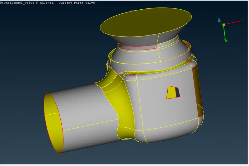
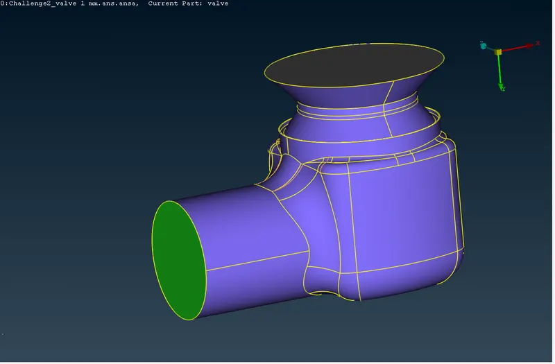
(Before) (After)
After creating a new surface which is missing have to close the model by filling the hole, where the model is open. After the filling holes have to check the geometrical error of the valve. We can see the images before and after the filling hole view. After the checking of geometrical errors has to solve the error like overlapping surfaces and errors of single cones and triple cones.
One more feature we use is the properties manager which specifies the surface or entities with a specific name and colour which we called as PID manager, in this PID manger we create the name section for each entity, and in this valve, we can assignee as inlet, outlet, body, spring, base surface, valve head and column which will help us for a fine mesh of the entities we can see it later. After doing this we can see some overlapping surfaces will create which will give some triple cone errors which have to be cut as per our requirement and remove the unused triple cone which gives us the error in the geometrical checking after doing this we can move to the mesh module. What we will do in the mesh module we can discuss below.
Use of mesh module
Here we use 3 different mesh lengths of 1mm, 3mm and 5mm for the whole model which gives different accuracy of mesh parameters. In the mesh module we give the mesh length for perimeters and macros after that we use the mesh parameters and quality criteria for giving the element type as tria and mesh length with minimum and maximum length of meshing after that we use spot mesh for meshing the valve. We can see the 3 different types of mesh length and observe the result.
For 1mm mesh length
we can see the mesh quality of the model for every entity in the valve.
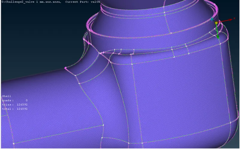
(Meshing of the body)
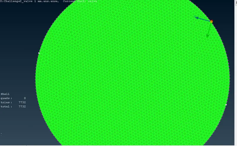
(Meshing of outlet)
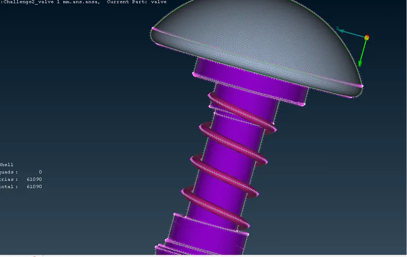
(Inner entities with meshing)
Here we take the mesh length of 1mm and minimum and maximum lengths are 0.5mm and 2mm in the first two images of meshing which is body meshing and outlet of the valve in the third one showing all the inner entities of valve like spring, column, base surface, column and valve head meshing show fine mesh which quality is better where element size is small gives a perfect meshing of the entities.
For 3mm mesh length
When we take the 3mm mesh length in the mesh parameters and in quality criteria we take the minimum length of 2mm and a maximum length of 5mm as we can see in the below images.
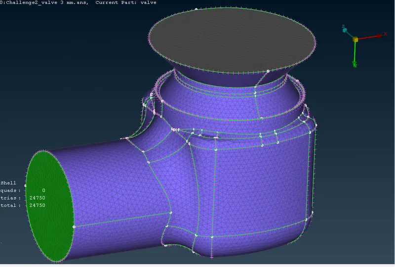
(Mesh of body)
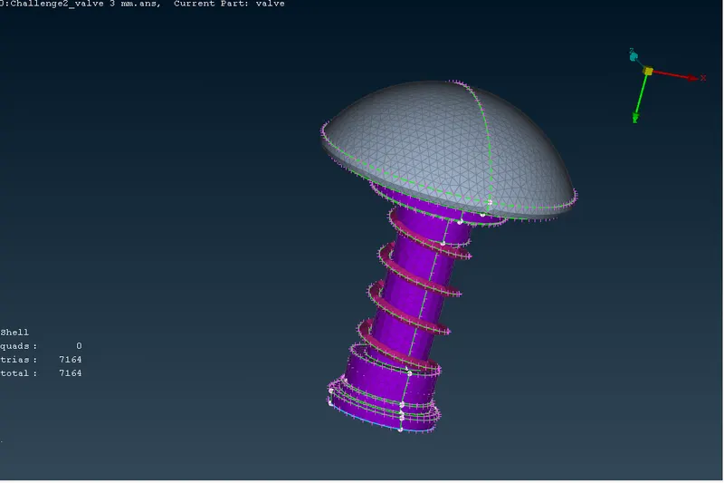
(Mesh of inner entities)
In these meshing images, we can able to see the meshing of all the entities with a mesh length which gives some accuracy to the mesh
For 5mm mesh length
As we see the other two mesh sizes here also we will apply the same procedure with different values of mesh length of 5mm with a minimum mesh length of 3mm and a maximum mesh length of 7mm we can see the images below.
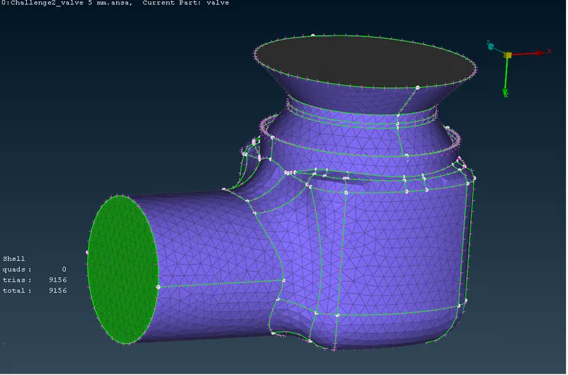
(Body mesh)
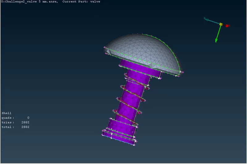
(Inner entities mesh)
Result
In the previous discussion and images, we can see and know that when the mesh size changes the element structure also changes the quality of the product also changes. When we simulate the valve model with different mesh lengths the result is different. Lets discuss about a entity spring with different mesh sizes:
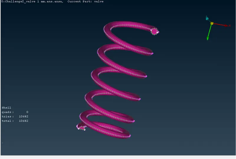
(Mesh of spring with 1mm mesh length)
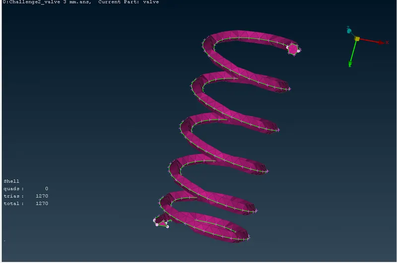
(Mesh of spring with 3mm mesh length)
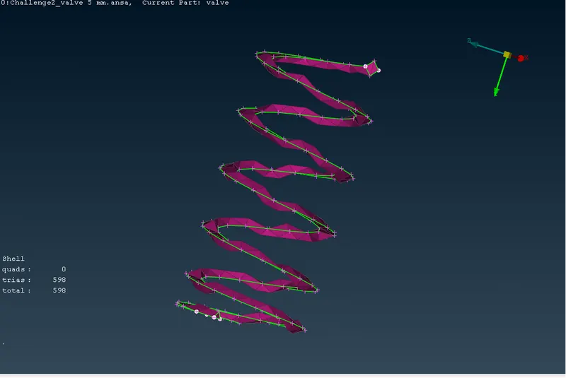
(Mesh of spring with 5mm mesh length)
As we see when the mesh length of the elements increases the number of tria elements decreases. Here we can able to know the good mesh quality is given by the mesh length of 1mm it gives better accuracy of meshing. We can compare the other elements with the increasing meshing length order.
Conclusion
From the above discussion, we can see the different mesh length gives the different element number. The number of tria elements increases when the mesh length is decreased. For the simulation of the valve model, the more accurate result will given where the number of tria elements is higher, here 1mm mesh length gives fine mesh which quality is good among the 3 mesh lengths.