Week 3 Challenge : CFD meshing on Turbocharger
Ami
To check the error in the turbocharger model, assign PIDs and make an appropriate volume mesh.
Procedure
The turbocharger model consists of some component compressor casing, turbo casing, shaft, 2 stages of blades and impeller. For the volumetric meshing, we have to do some steps in different modules in ANSA. In every module, we will do different operations we have to use 3 modules for this operation TOPO module, surface mesh module and volume mesh
Use of TOPO module
This module is used for the removal of the error present in the model and create assign the PIDs for doing this we have to follow these steps,
- Check the geometrical error
- Fix the single cons and triple cons error
- Create PIDs
- Assign PIDs
We can see the source file of the model where some surfaces are missing and some extra surfaces are having, which creates single cons for this error we have to create new surfaces by coons option. In some places not create a perfect surface here we have to insert hot points and multi-project to the other surface after that we can create a new surface.
In some places extra surfaces are present for remove this we can use intersect option which separates where the surfaces are intersected after that we can delete the unused surface. In the model someplace some extra surfaces are present which show triple cons error, in this place, we have to delete the extra surface and, in some place, overlapping surfaces are present have to fix this error by deleting these overlapping surfaces. We can see these in the below diagram:
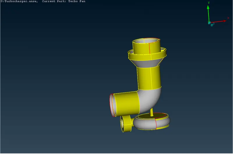
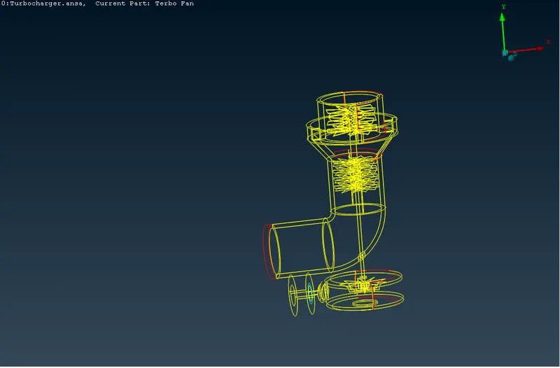
(With error source model) (Wire frame model with error)
We can see these two models where the red colour shows the single cons error and the blue colour shows triple cone error after fixing all the errors, we can find a final model which is shown below
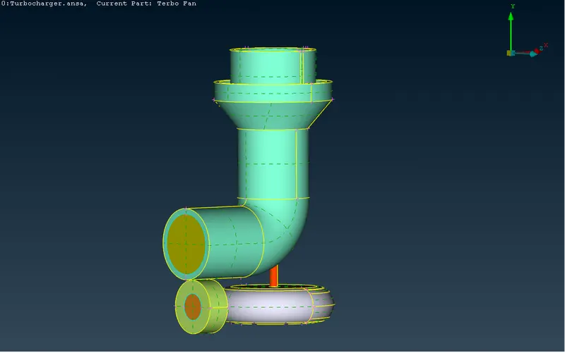
(After fixing all the errors)
In the above image, we can see the different colours are present these colours represent the assigned PIDs which are created in the properties manager. The PIDs we created are
- blade stage1
- blade stage2
- shaft
- bottom casing
- bottom casing feature
- impeller
- compressor inlet
- compressor casing
- compressor outlet
- turbo inlet
- turbo outlet
After assigning the PIDs we can go to the surface mesh module.
Use of surface mesh module
In the assigned PIDs, we use different minimum and maximum mesh lengths. In this module have to set the mesh properties as trial element and mesh length with minimum mesh length. After that, we can use quality criteria which assign the minimum and maximum mesh lengths all are different for different PIDs.
We have assigned the mesh length as follows
- blade stage 1 and blade stage 2 as mesh length 1mm with minimum 0.5mm and maximum 2mm mesh length
- compressor casing, compressor inlet and compressor outlet as mesh length 5mm with minimum 3mm and maximum 7mm mesh length
- shaft as mesh length 1mm with minimum 0.5mm and maximum 2mm mesh length
- bottom casing, bottom casing feature, turbo inlet and turbo outlet as mesh length 5mm with minimum 3mm and maximum 7mm mesh length
- impeller as mesh length 2mm with minimum 1mm and maximum 3mm mesh length
After assigning the mesh length we use the spot mesh option for the meshing of the PIDs we can see the meshing images below
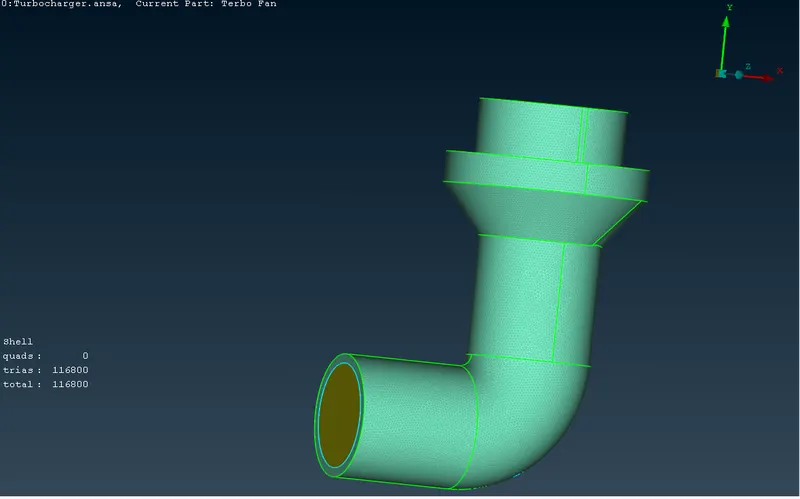
(Meshing of compressor)
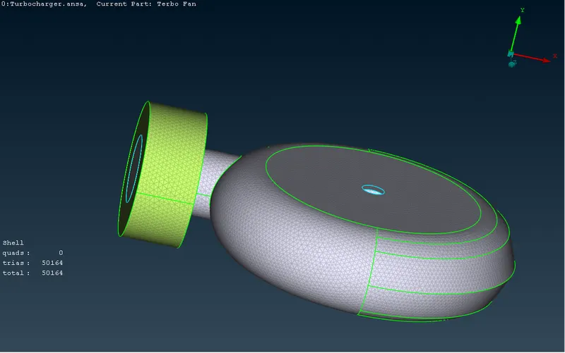
(Meshing of bottom casing)
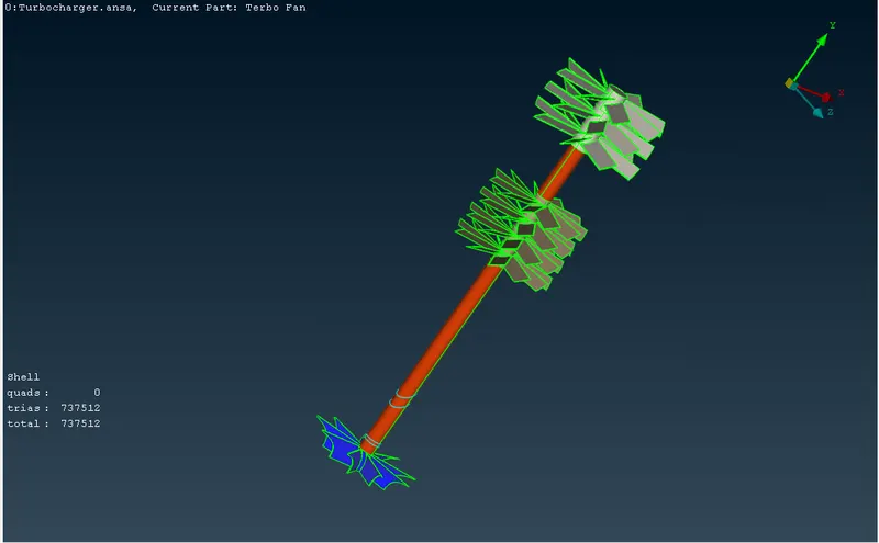
(Meshing of blades, shaft and impeller)
After the surface meshing, we can go to the volumetric mesh if any surface will unmeshed then the volumetric mesh is not possible that will show an error. If there is any error in the surface mesh have to fix the error then we can go to the volumetric mesh.
Use of volumetric mesh
In the volumetric mesh, we have to check first the errors in the surface mesh, after that, we can choose the option to define in the volume mesh which automatically detects the volume present in the surface mesh and give a list of the detected volume. In the rest of the volume have to mesh as tetra CFD meh type.
In the model where the fluid will flow at that volume, we have to find after that other volumes have to delete. In our model, we have fine the following volume where the fluid will flow
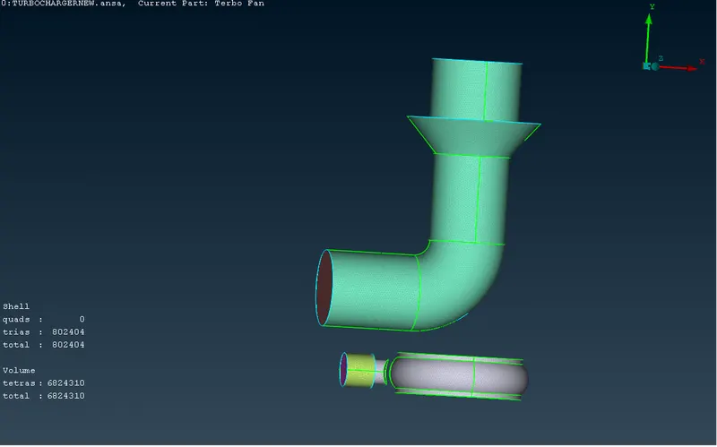
(Volumetric mesh of model)
In the above image, we can see all mesh types where the surface meshes as tria element type and the volumetric mesh as tetra CFD type element. This mesh shows only the volume where the fluid will flow.
Result
By the use of all three modules, we can define the volumetric mesh which gives the number of elements with a specific element type. The element sizes of the elements in this meshing are between 1m to 30mm which differ on the position of an element, in some positions the size is small where the fluid will compress and the size will be large were not compressed. We will see this in the later cross-sectional view of the image.
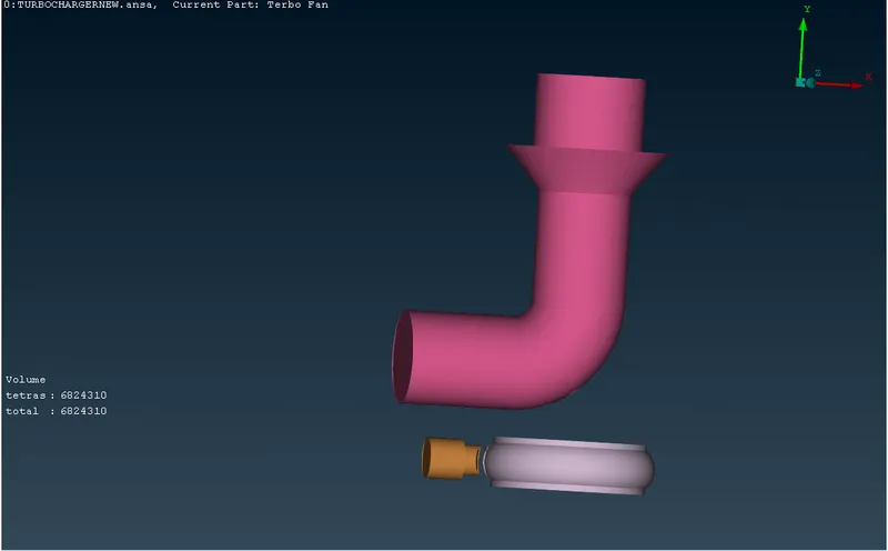
(Volumetric mesh with PIDs)
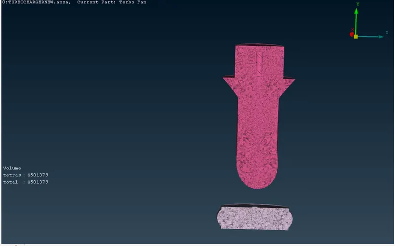
(Cross-sectional view of volumetric meshing)
Conclusion
Through this modelling process, we have used many more options to fix the error and do surface mesh as well as the volumetric mesh. After that, we can do the simulation of the model for a boundary condition.