Week 8 - Simulating Cyclone separator with Discrete Phase Modelling
Aim:
The goal of this project is to analyse a cyclone separator and determine the separation efficiency and pressure drop.
Objective:
1. To describe four empirical models used to calculate the cyclone separator efficiency in a few words.
2. To determine the separation effectiveness of a specific cyclone separator model by altering the particle diameter from 1 m to 5 m. Discuss the outcomes.
3. Calculate the separation efficiency and pressure drop in each scenario for a specific cyclone separator type by altering the particle velocity from 1 m/sec to 5 m/sec. Discuss the outcomes. [For all scenarios, use a particle diameter of 5 m and maintain the flow velocity the same as the particle velocity.
Theory:
Cyclone Seperator:
Cyclone separators are separation devices that remove particulate particles from flue gases using the concept of inertia. Because they remove bigger bits of particulate matter, a cyclone separator is one of numerous air pollution control equipment known as pre-cleaners. This eliminates the need for finer filtering technologies to deal with larger, more abrasive particles in the future. A multi-cyclone separator system may also work in parallel with many cyclone separators.
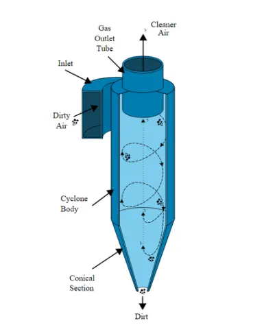
It's vital to remember that cyclones come in many shapes and sizes. The size of the cyclone is mostly determined by the amount of flue gas that must be filtered; consequently, larger operations require larger cyclones. For example, one cyclone type may have several distinct models, ranging in size from 1.2-1.5 metres tall (approximately 4-5 feet) to around 9 metres (30 feet)—roughly the same height as a three-story structure.
Working:
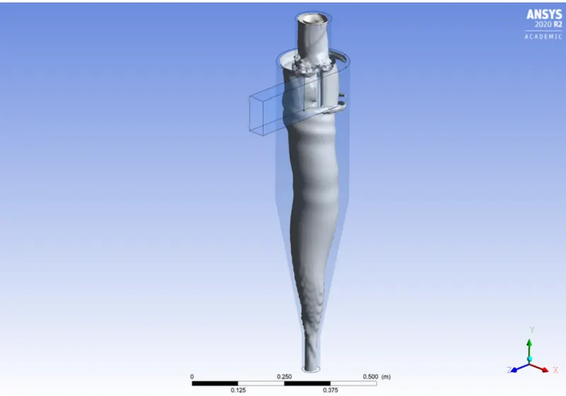
Cyclone separators function similarly to centrifuges, but with a constant supply of contaminated air. Dirty flue gas is pumped into a chamber in a cyclone separator. A spiral vortex forms inside the chamber, similar to that of a tornado. The separation and spiral creation are seen in the diagram below. Because the lighter components of this gas have less inertia, they may be affected by the vortex and move up it more easily. Larger particulate matter components, on the other hand, have higher inertia and are less easily impacted by the vortex.
Most cyclones are designed to manage and remove particulate matter with a diameter greater than 10 micrometres. High-efficiency cyclones, on the other hand, are designed to work with particles as tiny as 2.5 micrometres. Furthermore, these separators are ineffective when dealing with excessively big particles. Gravity settling chambers or momentum separators are a superior solution for particles smaller than 200 micrometres.
Cyclone separators are the least costly of all the particulate-control systems. They're frequently utilised as a pretreatment step before flue gas passes through more effective pollution control equipment. As a result, before the flue gas reaches the fine filtering stages, cyclone separators might be thought of as "rough separators."
Effectiveness:
Cyclone separators can typically remove between 50 and 99 percent of all particle matter from flue gas. The ability of the cyclone separators to remove this materials is mostly determined by particle size. When there is a lot of lighter particulate matter, it's harder to sort these particles apart. As a result, cyclone separators are most effective on exhaust gases containing substantial levels of large particle matter.
Using cyclone separators has a number of benefits and drawbacks. To begin with, cyclone separators are advantageous because they are inexpensive to build and maintain, and they do not have any moving components. As a result, maintenance and operational expenditures are kept to a minimum. Second, the eliminated particle debris is gathered when it is dry, making disposal easier.
For cyclone separator efficiency, empirical models used:
a. IOZIA and LEITH Model:
The logistic model established by Iozia and Leith (1990) is a modified version of Barth's (1956) model, which is based on force balance. A particle transported by a vortex is subjected to two forces: centrifugal force Z and flow resistance W, according to the model.
The length of the core, zc, and the diameter of the core, dc, are given as
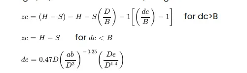
The core length zc and slope parameter expression, which are additions made by Iozia and Leith to the original Barth (1956) model, are developed based on the statistical analysis of experimental data of cyclone with D = 0.25 m. The particle diameter dpi may be used to calculate the collecting efficiency i.

b. LI and WANG Model:
The Li and Wang (1989) model takes into account turbulent diffusion at the cyclone wall as well as particle bounce or re-entrainment. The particle distribution in the cyclone is expressed as a two-dimensional analytical equation. The following assumptions guided the development of Li and Wang's model:
1. For uncollected particles inside the cyclones, the radial particle velocity and the radial concentration profile are not constant.
2. The following are the boundary conditions when the turbulent diffusion coefficient and particle bounce re-entrainment on the cyclone wall are taken into account:
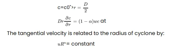
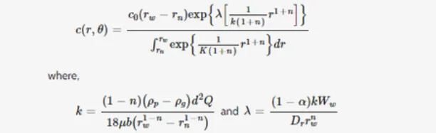
The following is the concentration distribution in a cyclone:
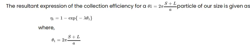
c. KOCH and LICHT model:
The collection hypothesis developed by Koch and Licht in 1977 identified both the distribution of gas residence periods inside cyclones and the intrinsically turbulent nature of cyclones. Koch and Licht make the following additional assumptions when describing particle mobility in the entrance and collecting regions:
1. There is no slip in the tangential direction between the particle and the gas because the tangential velocity of a particle is equal to the tangential velocity of the gas flow.
2. The tangential velocity and cyclone radius are linked by
The grade efficiency I is calculated using a force balance and a particle collecting equation.
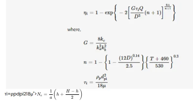
G is a factor related to the configuration of the cyclone, n is related to the vortex and τ is the relaxation term.
d. LAPPLE Model:
Without taking into account flow resistance, the Lapple (1951) model was established based on force balance. Lapple made the supposition that a particle entering the cyclone is dispersed uniformly over the inlet hole. In the cyclone, the particle that travels from the entrance half-width to the wall is gathered with a 50% efficiency. Lapple (1951) developed a semi-empirical connection to Calculate a 50% cut diameter, dpc is
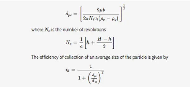
The result section calculates the separation efficiency based on this model and compares it to the experimental results for 5 micrometre at 3 m/s.
Geometry:
a. Select Fluid flow fluent, then begin by changing geometry.
b. Open spaceclaim and import the model's step file.
c. Volume extract the model so that we may examine the cyclone separator's fluid flow.
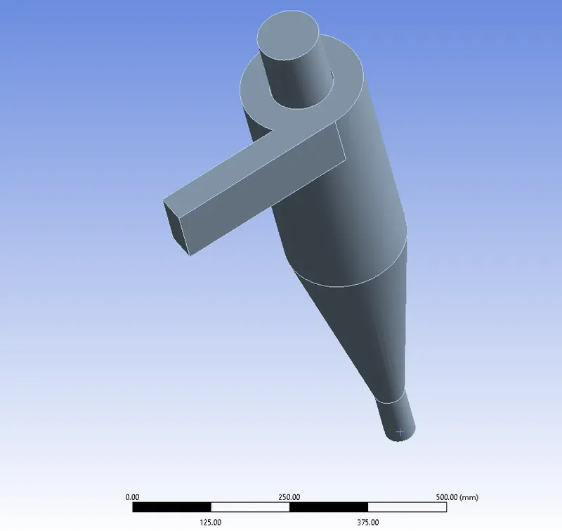
d.Since we are only concerned with the fluid flow and not the exterior surface, hide the prior geometry and suppress the physics.
Mesh Stats:
Main element size: 7.5mm
Method = Cartesian method
Cartesian element size= 5.2623mm
No. of elements= 216784
Mesh Quality:
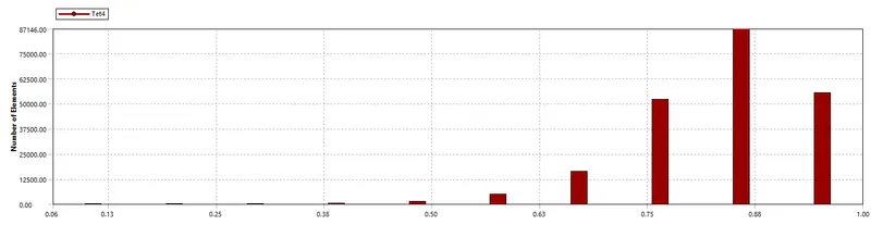
a.After meshing the model, pick generate mesh to create the basic mesh. However, since mesh refinement affects how many particles enter the inlet, it is preferable to refine the mesh suitably.
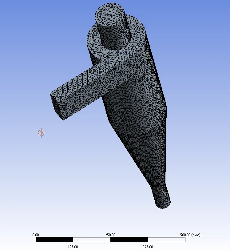
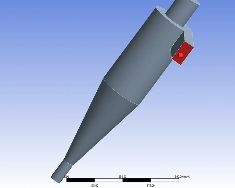
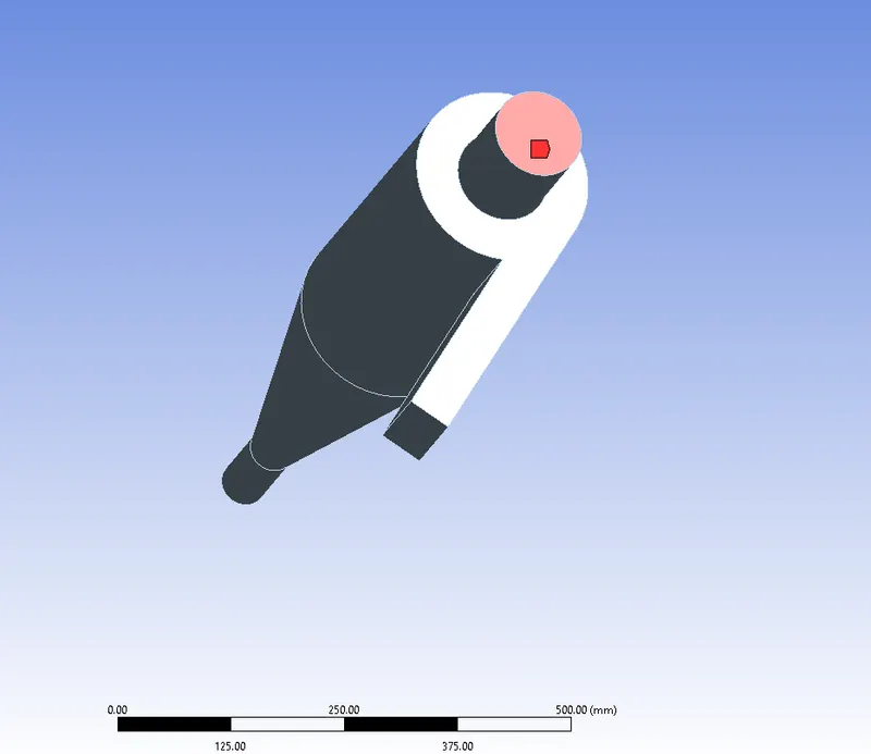
b. Assign the names of the inlets and outlets by using named selections.
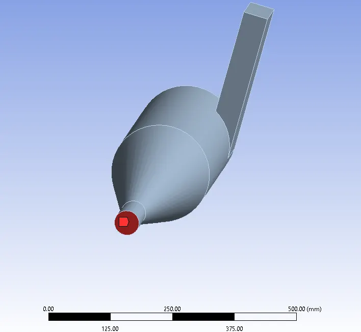
Fluent Setup:
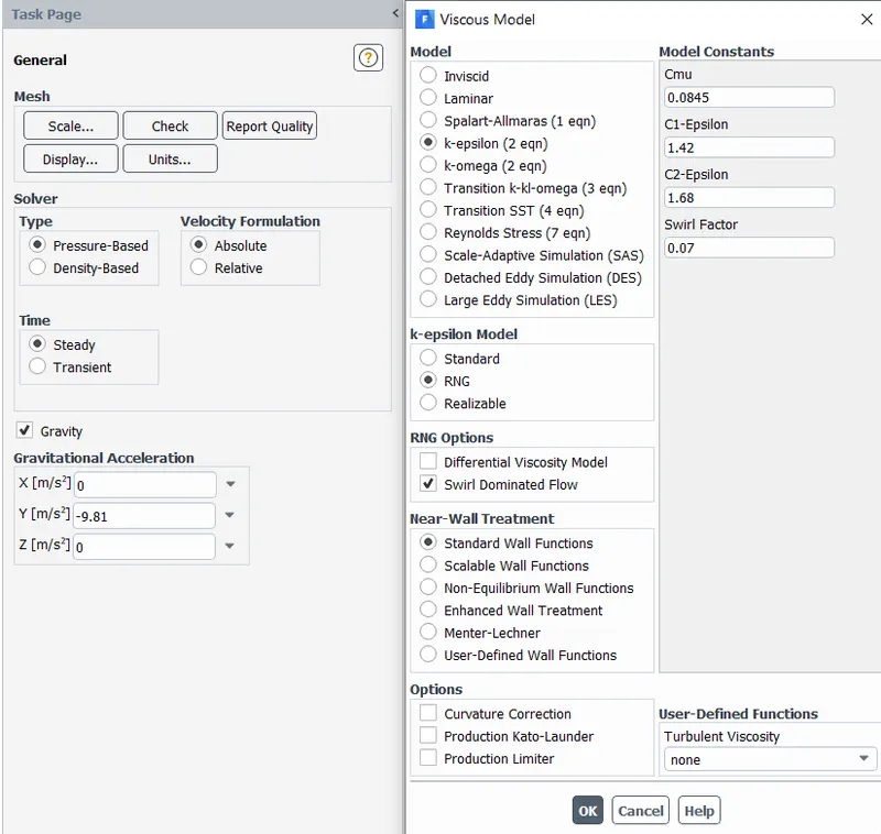
1. Physics:
Solver - Pressure based
Time - Steady time.- velocity Formulation - Absolute
- Gravitational Acceleration - Enabled in y-direction = -9.81.
- Viscous Model -
- Model - k-Epsilon
- k-epsilon Model - RNG
- RNG Option - Swirl Dominated Flow
- Near Wall Treatment - Standard Wall Functions
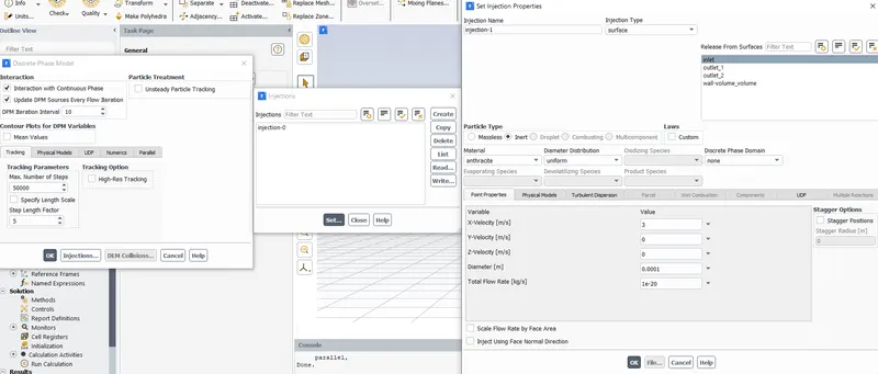
2. Discrete Phase Modeling:
The flow of a discrete phase with a continuous flow is represented using the discrete phase modelling (DPM) technique. DPM is used to follow specific particles as they move through a continuum fluid. The Euler Lagrange method is used in the Lagrangian discrete phase model.
The Navier Stokes equation is used to solve the fluid phase, which is represented as a continuum, while the dispersed phase is solved by following a large number of particles, bubbles, or droplets through the predicted flow field. The fluid phase and the scattered phase are capable of exchanging mass, energy, and momentum.
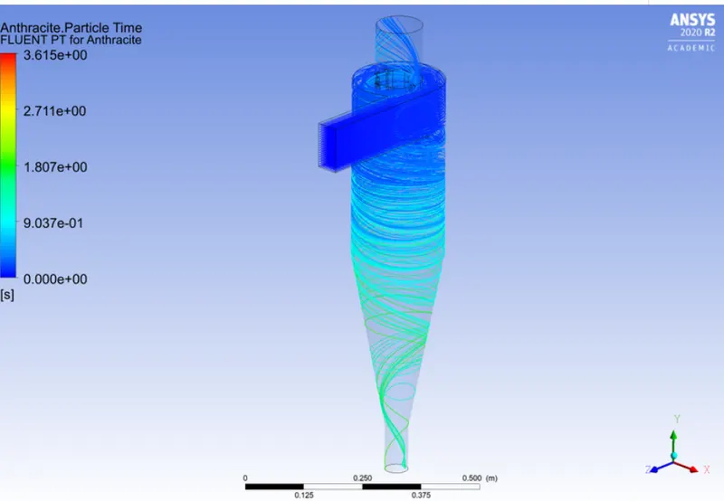
Solid particles of sizes between 1 and 5 micrometres are represented in this instance as a distinct phase in a continuum.
1. Facilitated coupling with continuous phase to promote interaction
2. Update DPM sources with each flow iteration enabled - Enabling this option allows for the calculation of the particle source term at each flow iteration.
3. Cell averaged variable value is permitted for contour plots for DPM variables, which are not enabled.
4. Tracking parameters - Maximum number of steps - 50000 - This specifies the maximum number of timesteps to compute a single particle trajectory.
5. Specify length scale - The timestep size can also be adjusted using this option.
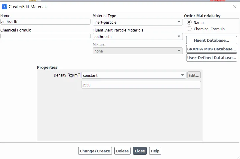
Material Used: Anthracite( Dirty Air which is to be Filtered.
3. Boundary Conditions:
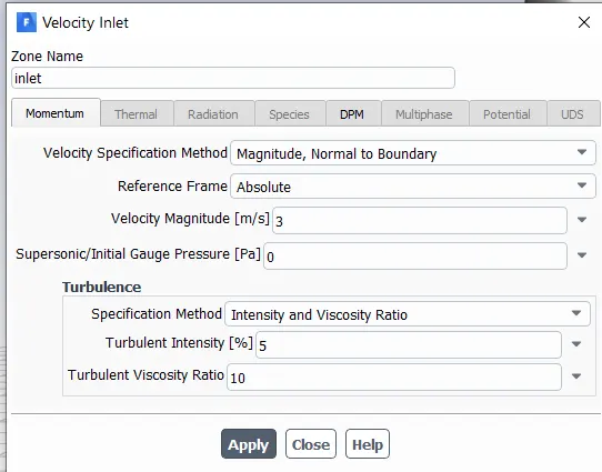
Inlet: - Velocity-Inlet
Velocity Magnitude -
Part 1- Constant velocity of 3m/s.
Part 2- Varying velocity from 1m/s - 5m/s
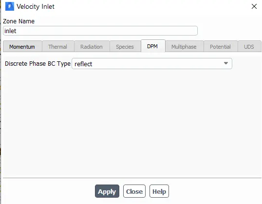
DPM - Reflect
Reflect - The particle rebound off the boundary in question with a change in its momentum as defined by the coefficient of restitution.
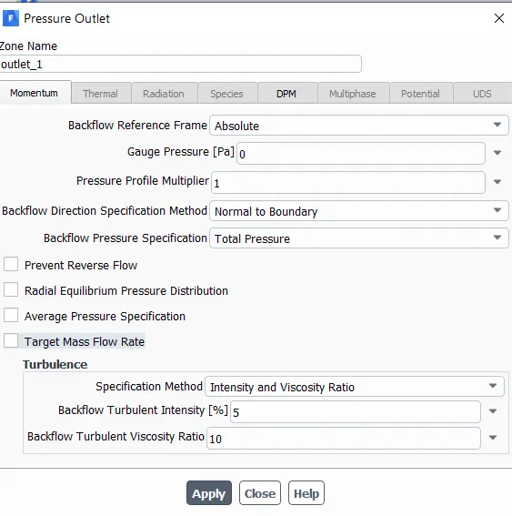
Outlet 1- Pressure-Outlet
Pressure - 0 Pa
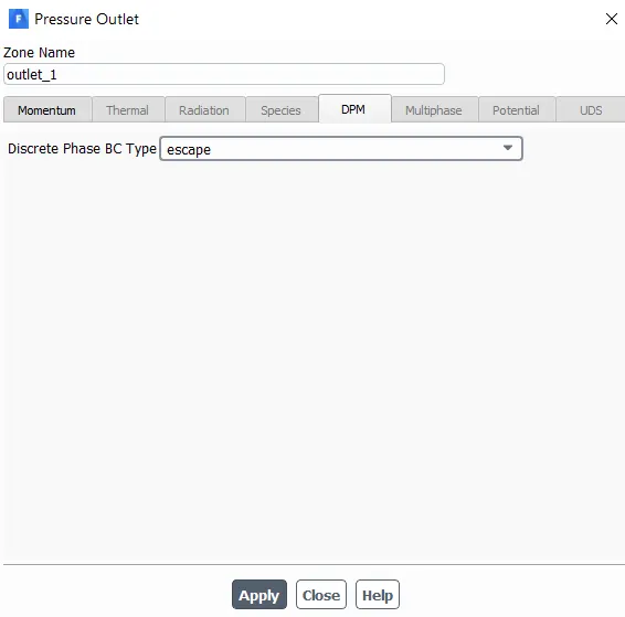
DPM - Escape
Escape - The particle is reported as having "escaped" when it encounters the boundary in question. Trajectory calculated are
terminated.
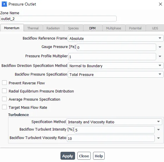
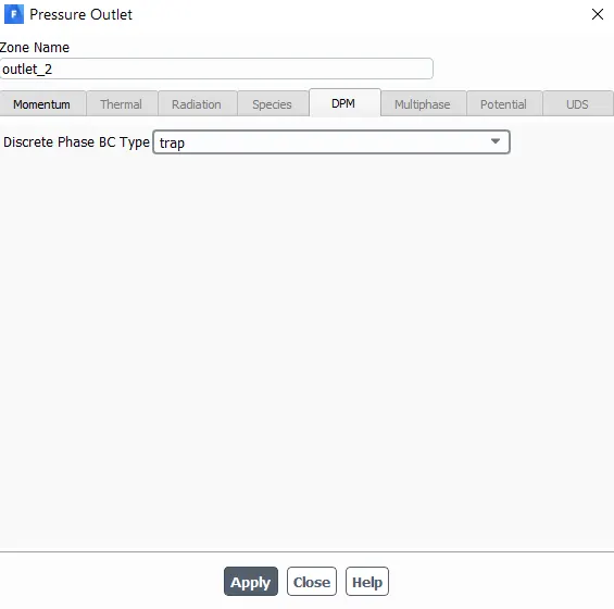
Outlet 2 - Pressure-Outlet
Pressure - 0 Pa
DPM - Trap
Trap - The trajectory calculation are terminated and the fate of the particle is recorded as " trapped ". In the case of the evaporating
droplet, their entire mass instantaneously passes into the vapour phase and enters the cell adjacent to the boundary. In the case of a
combusting particle, the remaining volatile mass is passed into the vapour phase.
4. Solution:
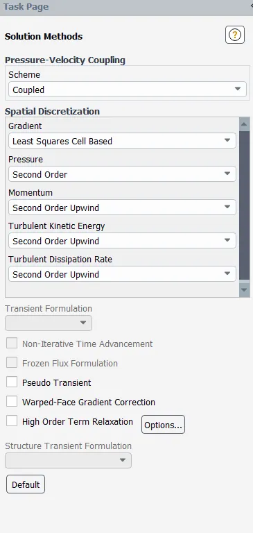
Solution method and solution control:
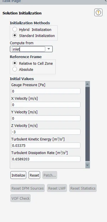
Standard Initialisation:
Results and Analysis:
Part 1: Analysis of a given cyclone separator model by varying the particle diameter from 1 μm to 5 μm at 3m/s for both particle
and flow velocity and calculate the separation efficiency in each case.
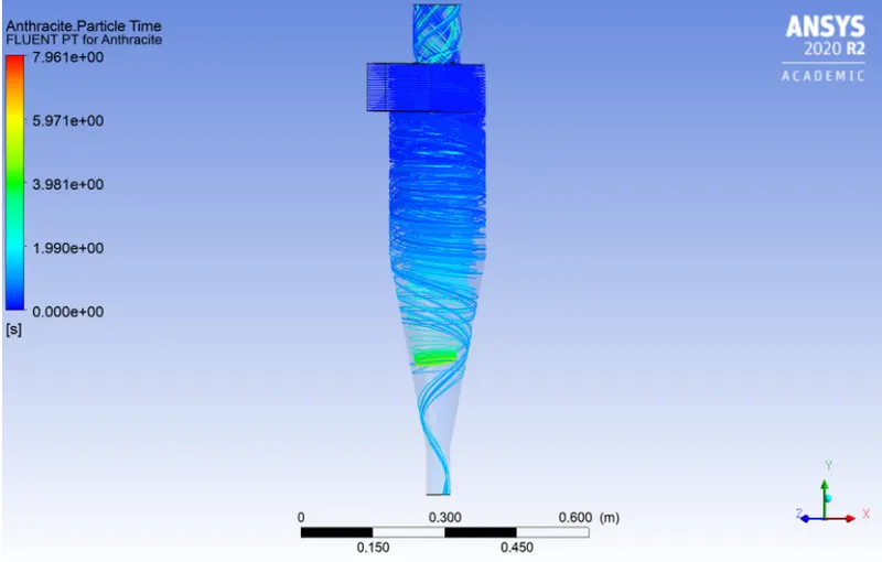
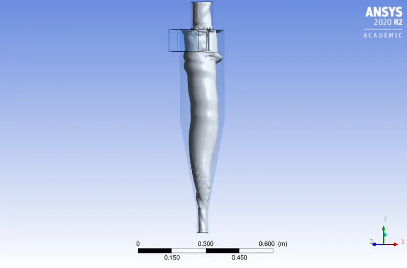
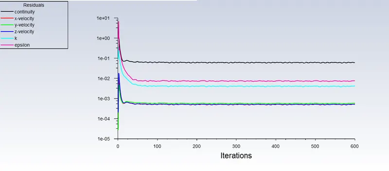
1. At 1 Micrometre:
a. Flow Contour and Vortex:
b. Residuals
c. Animations
2.
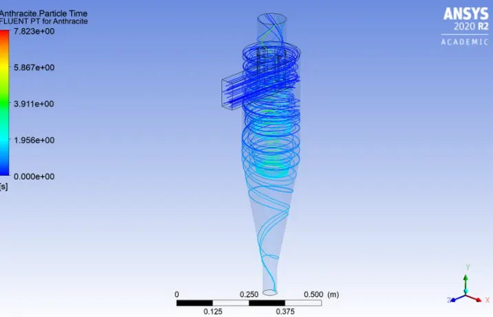
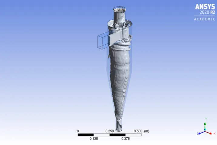
At 2 Micrometre:
a. Flow Contour and Vortex:
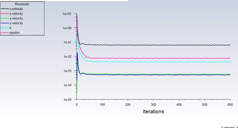
b. Residuals
c. Animations
3.
At 3 Micrometre:
a. Flow Contour and Vortex:
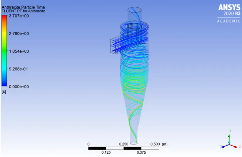
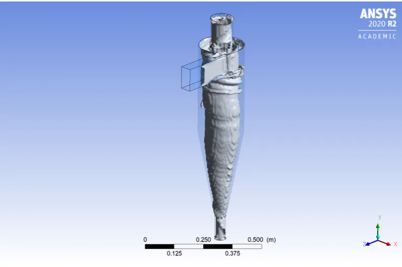
b. Residuals
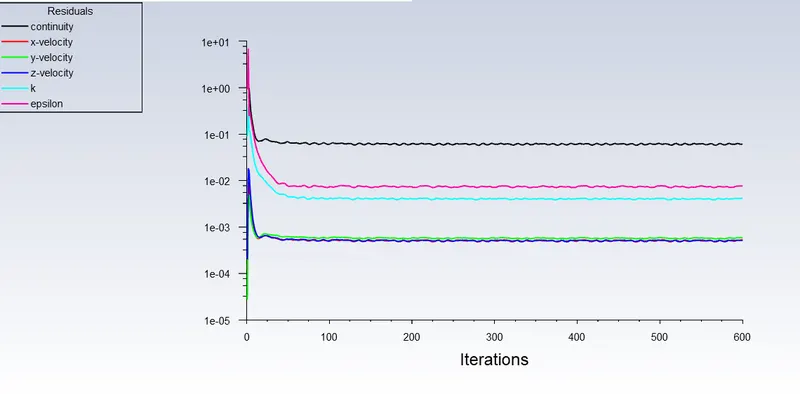
c. Animations
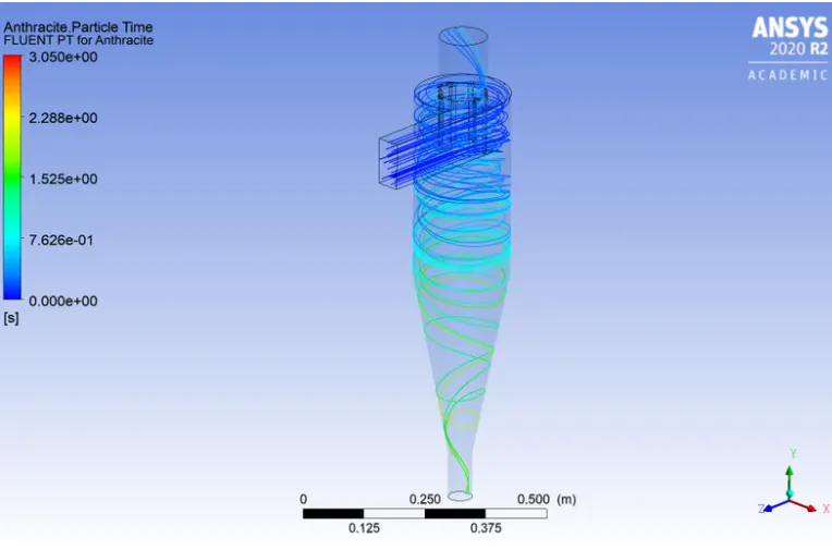
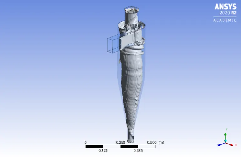
4. At 4 Micrometre:
a. Flow Contour and Vortex:
b. Residuals
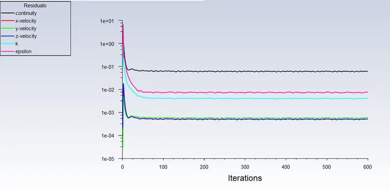
c. Animations
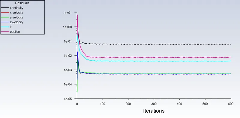
5. At 5 Micrometre:
a. Flow Contour and Vortex:
b. Residuals
c. Animations
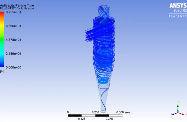
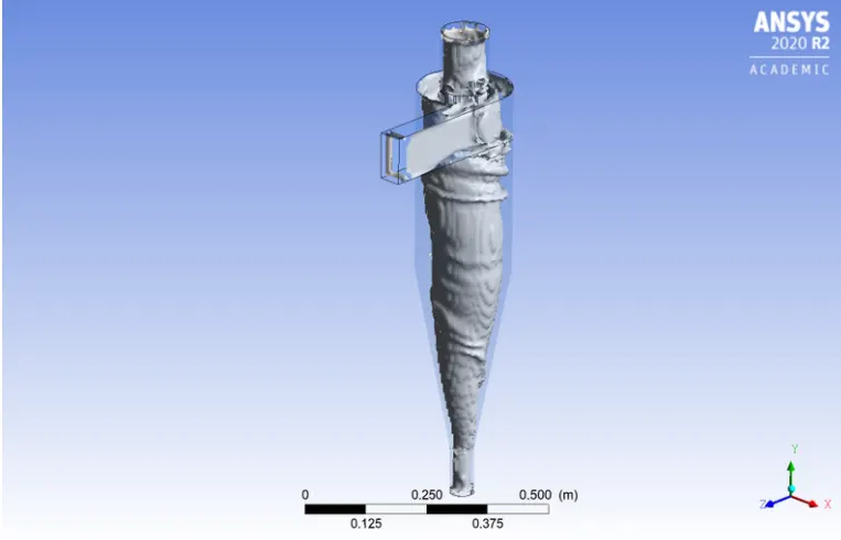
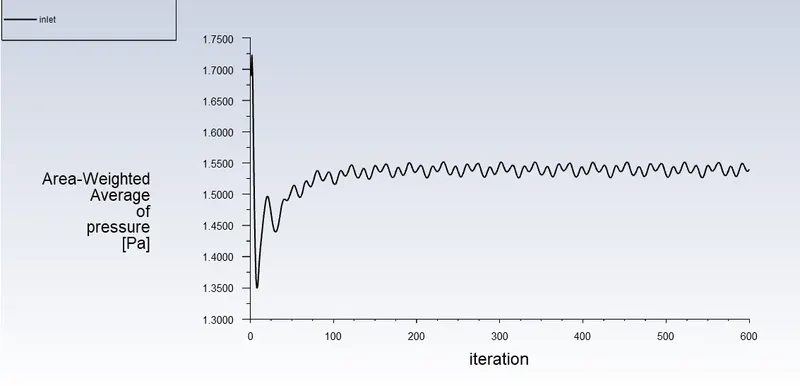
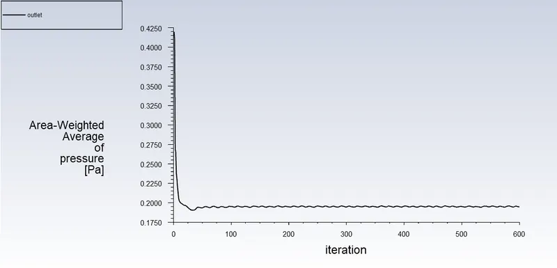
Part 2: Calculating the separation efficiency and pressure drop for each scenario while adjusting the particle velocity from 1 m/sec to 5 m/sec at 5 micrometres in a particular cyclone separator model.
1. at 1m/sec
a. Flow Contour and Vortex
b. Residuals
c. Pressure at Inlet and Outlet
d. Animations
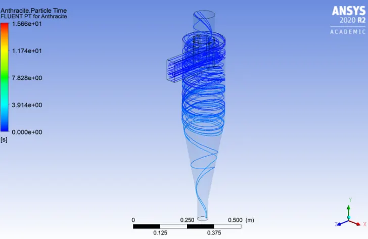
2. at 2m/sec
a. Flow Contour and Vortex
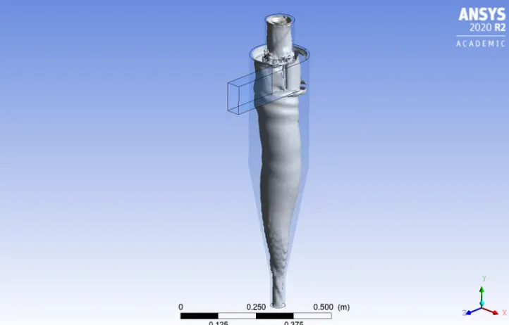
b. Residuals
c. Pressure at Inlet and Outlet
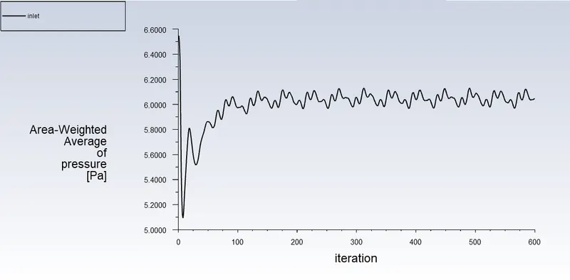
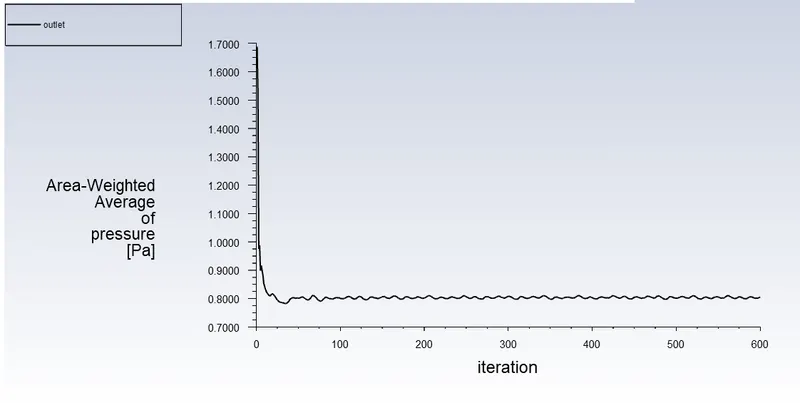
d. Animations
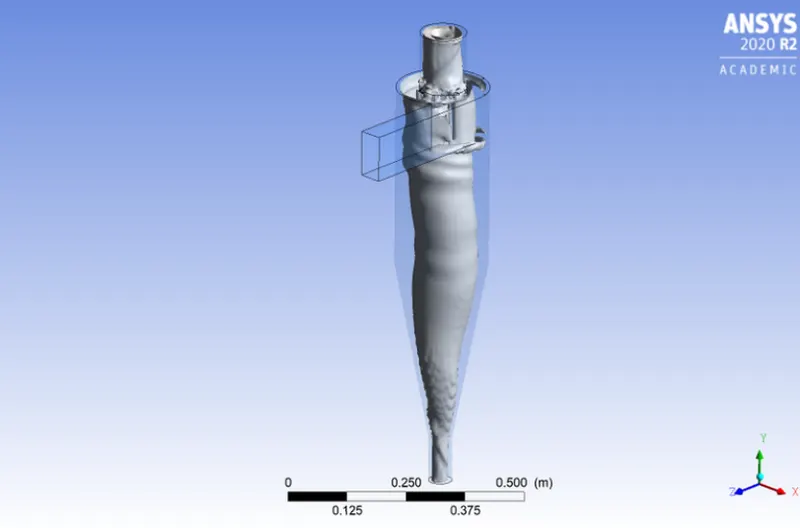
3. at 3m/sec
a. Flow Contour and Vortex
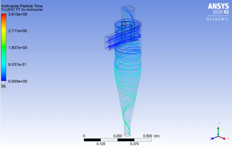
b. Residuals
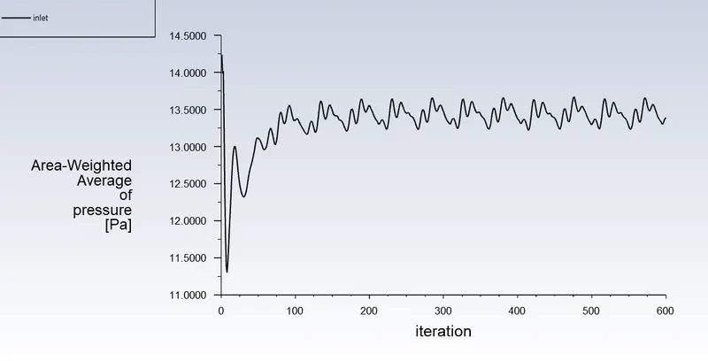
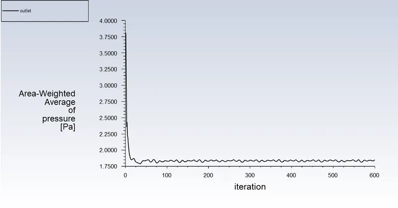
c. Pressure at Inlet and Outlet
d. Animations
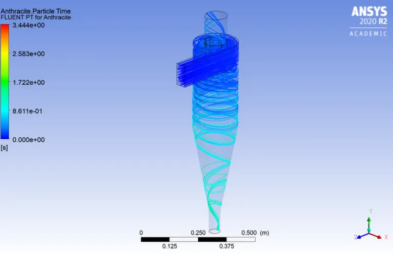
4. at 4m/sec
a. Flow Contour and Vortex
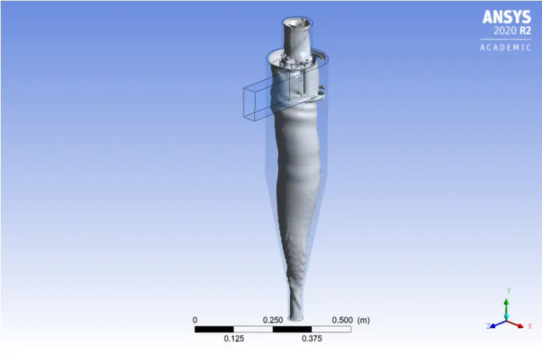
b. Residuals
c. Pressure at Inlet and Outlet
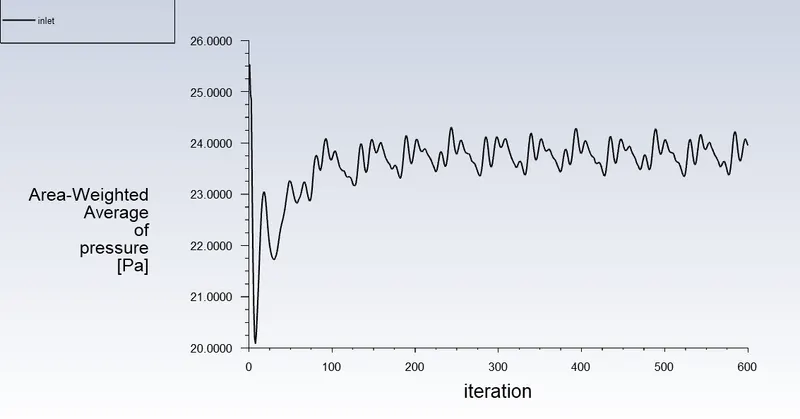
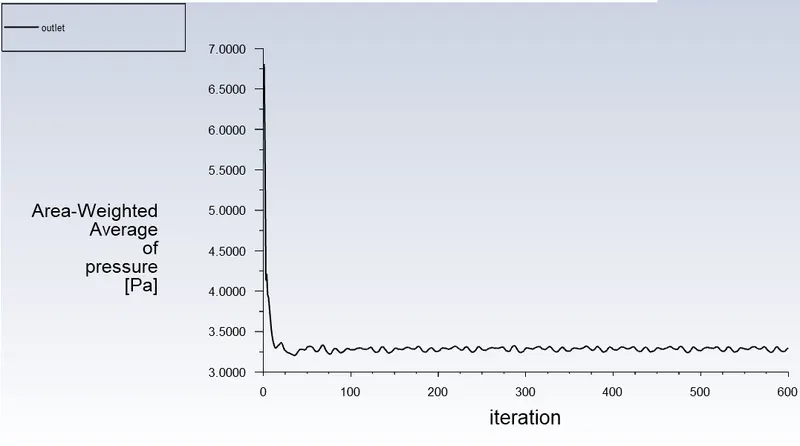
d. Animations
5. at 5m/sec
a. Flow Contour and Vortex
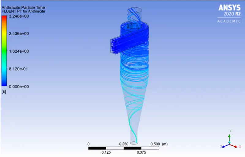
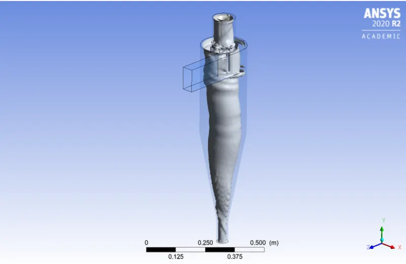
b. Residuals
c. Pressure at Inlet and Outlet
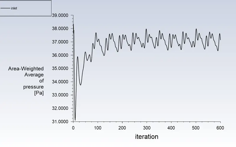
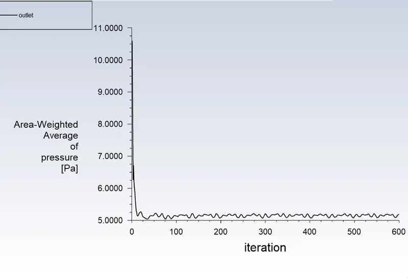
d. Animations
Seperation Efficiency:
It is described as the percentage of particles of a particular size that are collected in the cyclone as opposed to those that enter the cyclone. Experience has shown that raising particle mean diameter and density, increasing gas tangential velocity, lowering cyclone diameter, increasing cyclone length, and extracting gas and solids simultaneously through the cyclone legs all boost the separation efficiency of cyclone separators.
The separation efficiency in this instance is defined as the ratio of concentration that has been removed from the feed stream to the starting concentration in the feed stream, depending on the particle history data. Ratio of the tracked particle total to the number of captured particles in this scenario.
Separation efficiency = no. of particles trapped / no. of particles tracked
Pressure Drop:
In a cyclone separator, the pressure drop throughout the cyclone is crucial. The performance characteristics of a cyclone are substantially impacted by the pressure decrease. The entry and exit losses, friction, and kinetic energy losses inside the cyclone all contribute to the overall pressure reduction in the cyclone. The body often experiences the most pressure reduction as a result of whirling and energy loss.
The difference in total pressure between two places on a fluid-carrying network is known as pressure drop.
Pressure drop, = Total inlet pressure - Total Outlet Pressure (escape)
The outlet-top is taken into account in the calculation of pressure drop since in this scenario the escape DPM condition is provided to the outlet-top.
Analysis:
1. For Varying Particle Diameter at 3m/sec
| Case | Particle Size(in μm) | Particles tracked | Particles escaped | Particles trapped | Particles Incomplete | Seperation Efficiency |
| 1 | 5 | 196 | 124 | 37 | 35 | 0.1887 |
| 2 | 4 | 196 | 114 | 45 | 37 | 0.2295 |
| 3 | 3 | 196 | 110 | 54 | 32 | 0.2755 |
| 4 | 2 | 196 | 101 | 59 | 36 | 0.3010 |
| 5 | 1 | 196 | 108 | 62 | 46 | 0.3163 |
2. For Varying Particle Velocities at 5 micrometer particle diameter
| Case | Velocity (m/sec) | Particles Tracked | Particles Escaped | Particles Trapped | Particles Incomplete | Pressure Drop | Seperation Efficiency |
| 1 | 1 | 196 | 32 | 22 | 142 | 1.34504189 | 0.1122 |
| 2 | 2 | 196 | 27 | 37 | 132 | 5.24092391 | 0.1887 |
| 3 | 3 | 196 | 124 | 37 | 35 | 11.5374005 | 0.1887 |
| 4 | 4 | 196 | 128 | 67 | 1 | 20.652886 | 0.3418 |
| 5 | 5 | 196 | 130 | 65 | 1 | 31.9575837 | 0.3316 |
Conclusion:
- The two simulations outlined above demonstrate how separation effectiveness is influenced by the particles' diameter and velocity. Larger separation effectiveness results from increased diameter and velocity.
- In comparison to the particle's diameter, velocity has a more significant effect.
- Velocity affects the rate of pressure decrease. The pressure loss is nearly constant for constant velocity and different diameter diameters.
- A higher pressure drop results from increased velocity.