Week 8 - Simulating Cyclone separator with Discrete Phase Modelling
PROJECT REPORT
Aim:
Performing the analysis on the cyclone separator model by varying the particle size with a constant inlet velocity of 3m/s for particle and continuous phase velocity.
Also, calculate the separation efficiency and pressure drop
INTRODUCTION:
Cyclone Separator:
A cyclone separator is a device that uses centrifugal force to separate the solids from the carrier gas. This is widely used in industry at the initial stage of the clearing process as it has a low capital cost and maintenance cost
Working principle of cyclone separator
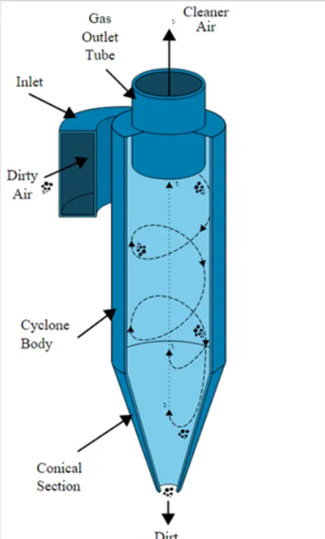
WORKING PRINCIPLE:
- Cyclone separator works much like a centrifuge, but we a continuous feed of dirty air.
- In a cyclone separator, dirty flue gas is fed into a chamber, which creates a spiral vortex, similar to a tornado. This spiral formation and the separation
- The lighter components of this gas have less inertia, so it is easier for then to be influenced the vortex and travel it up. Comparatively larger components of particulate matter have more inertia and are not as easily influenced by the vortex
- Since these larger particles have difficulty following the high-speed spiral motion of the gas, the particle hits the inner wall of the container and drops down in the collector
- Dur to the upside-down cone shape of the container the collection of these particles at the bottom of the container. The cleaned flue gas escapes the out the top of the chamber
This was the impurities in the gas can be removed effectively and easily with the help of a cyclone separator
MODELS USED TO CALCULATIONS IN CYCLONE SEPERATOERS
- Lozia and leith model:
Lozia and Leith logistic model is developed base on force balance. The model assumes that a particle carried by the vortex endures the influence of two force: a centrifugal force, z and a flow resistance, (W) the collection efficiency n of particle dis. Can be calculated from
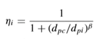
β is an expression for slope parameter derived based on the statistical analysis of experimental data of a cyclone with D=0.25 m given as

And dpc is the 50% cut size given by birth
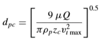
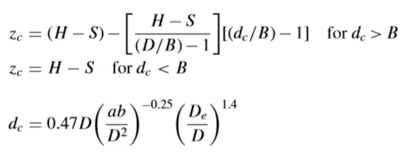
Where, core length, Zc , and core diameter, dc are given as
- Koche and licht model:
Koche and licht collection theory recognized the inherently turbulent nature of cyclone and the distribution of gas residence time within the cyclone
Koche and licht described particle motion in the entry and collection regions with the ad-200 additional following assumptions
Assumptions:
- The tangential velocity of a particle is equal to the tangential velocity of the gas flow, i.e. there is no slip in the tangential direction between the particle and the gas.
- The tangential velocity is related to the radius of the cyclone by u Rn = constant.
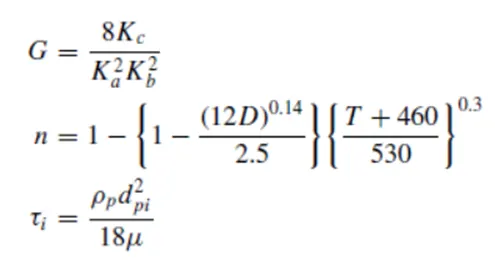
A force balance and an equation on the particles collection yields the grade efficiency

Were,
- Li and Wang Model:
- The Li and Wang model includes particle bounce or retainment and turbulent diffusion at the cyclone wall
- A two dimencional expression of particle distribution in the cyclone is obtained
- Li and Wang model was developwd base on the following assumptions
Assumptions:
- The radial particle velocity contraption profile is not constant for uncollected particles within the cyclone.
- Boundary condition with the consideration of turbulent diffusion coefficient and partic bounce retainment on the cyclone wall are c = c0 and ϴ = 0
The tangential velocity is related to the radius of cyclone by: u Rn = constant.
The concentration distribution in a cyclone is given as:
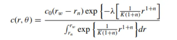
Were,
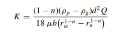
And,
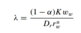
The Resultant expression of the collection efficiency of any size is given as,
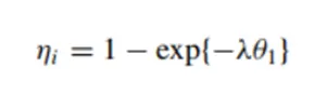
Were,
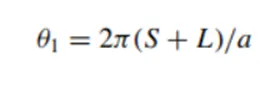
- LAPPLE MODEL:
- Lapple model was developed based on force balance without considering the flow resistance.
- Lapple assumed that a particle entering the cyclone is evenly distributed across the inlet opening
- The particle that travels from inlet half width to the wall in the cyclone collected with 50% efficiency.
- The semiempirical relation developed by lapple to calculate a 50% cut diameter, dpc ,is
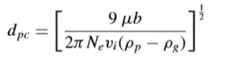
Where Ne is the number of revolutions
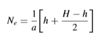
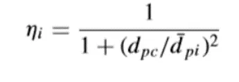
The efficiency of any size of the particle is given by
MODELING:
Geometry:
After importing the cyclone cylinder fine in the space claim go to prepare and choose extract volume,
For extracting the fluid volume
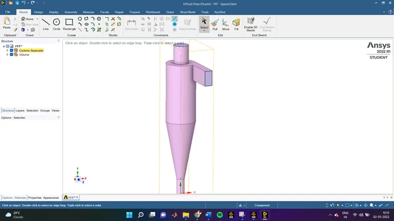
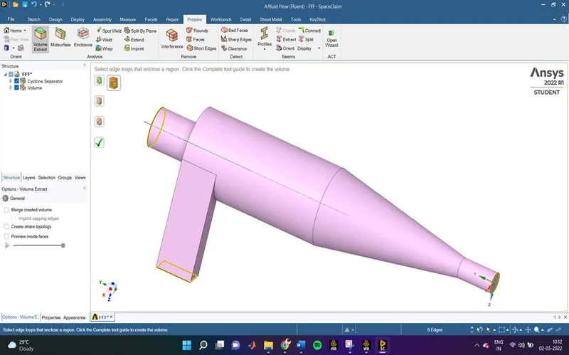
After extracting the fluid volume, we don’t need the solid walls of the cyclone separator for analysis so its an important step to surpass that part from physics, other wise you can see an error popping while meshing so right click on first option from geometry tree and click on supress from physics
The icon on the tree will change after this step
MESHING:
In meshing part to achieve the more no. of particles in the body movement, so the meh size in ,y simulation is 6mm
We also use input new method for shaping it in grid properly which is more accurate for this kind of simulation
Also, we can use a body sizing on the input plane so can increase the no. of inlet particle
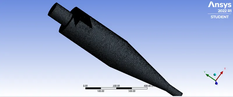
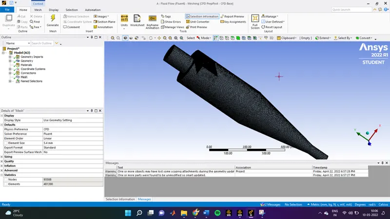
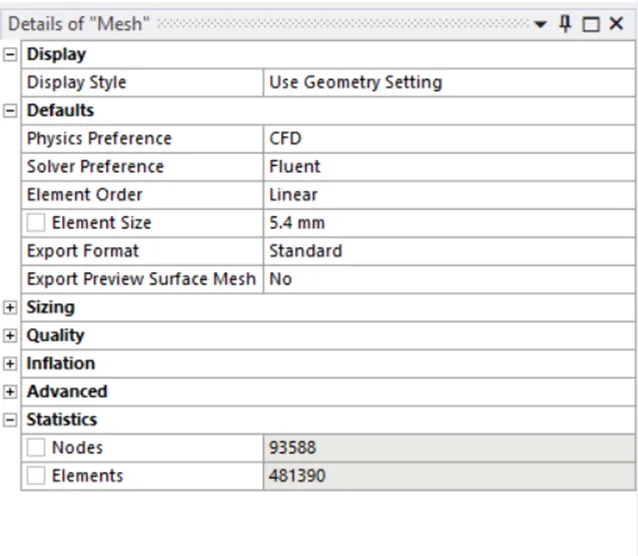
The total no. of cell for this simulation is 481390 nods
After that we have to assign name selection for inlet and two outlets
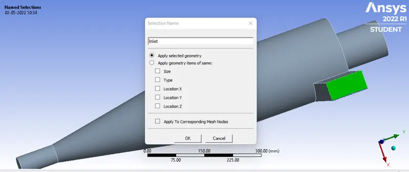
So, as shown in fig we need to click on every face and providing a name accordingly by clicking N
After that we are all set for Fluent
SETUP:
- General
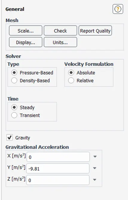
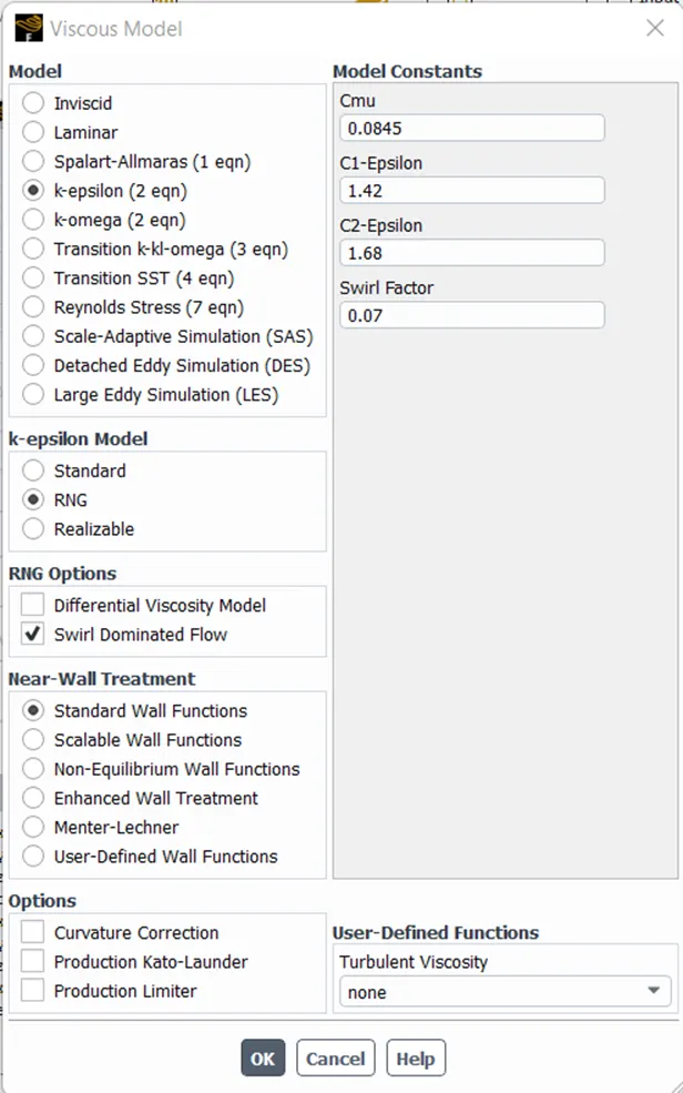
2 viscous model
- Direct phase model
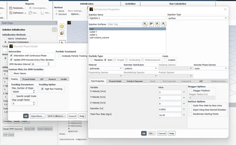
Here we have selected material as anthracite there are many other options as per need
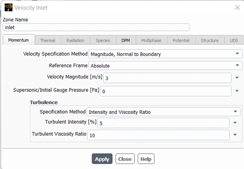
Now, setting boundary condition for inlet
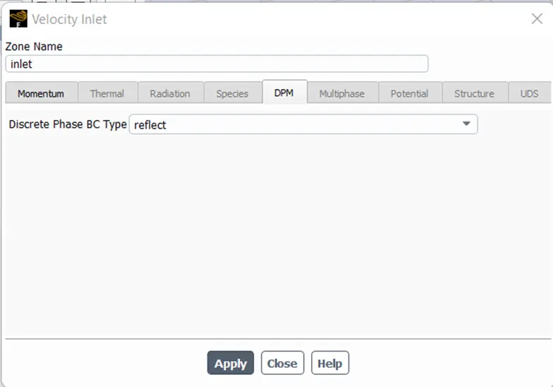
In DPM we have set the boundary condition as reflect as it ensures that the particle cannot escape from the inlet
- Solution
We can use standard initialization for this simulation, but first we use a SIMPLE model with a
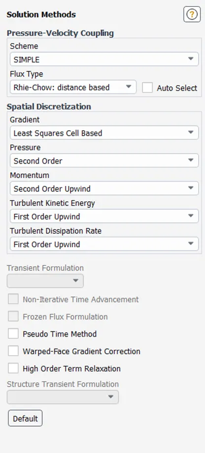
In this we are using second order upwind momentum for more accuracy
Now, we run the simulation for 600 iterations
After completing the calculation, we have to export the particle movement data so we can use it in post CFD
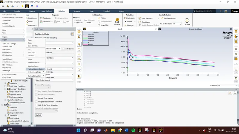
From file – Export – and Particle history data
Save the file at some location se we can import it later
RESULT:
Residuals:
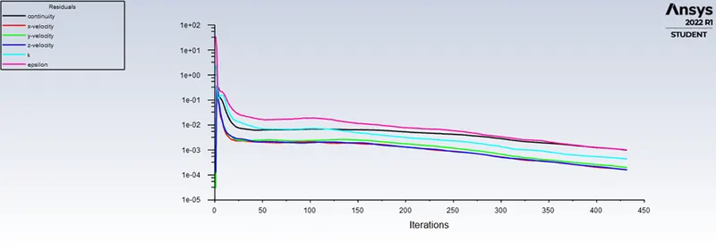
All solutions have almost same graphs for residuals, from residual plot we can confirm that the solution is converged
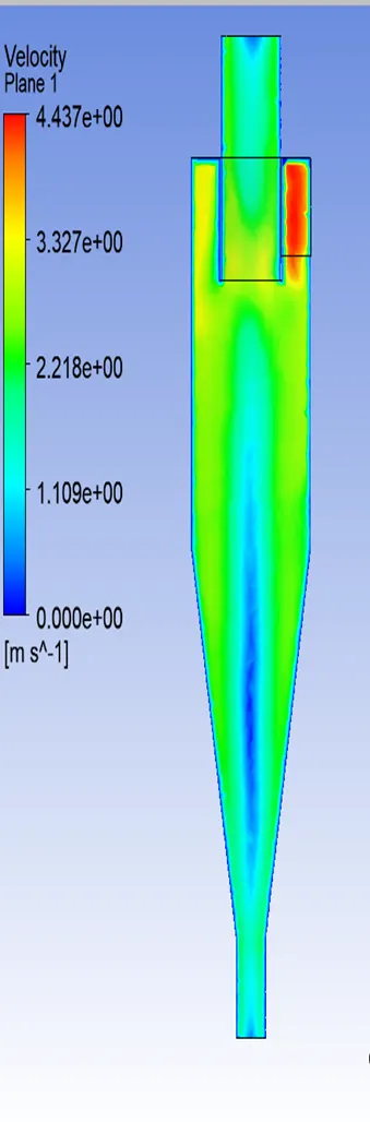
VELOCITY AND PRESSURE PLOT FOR 3M/S
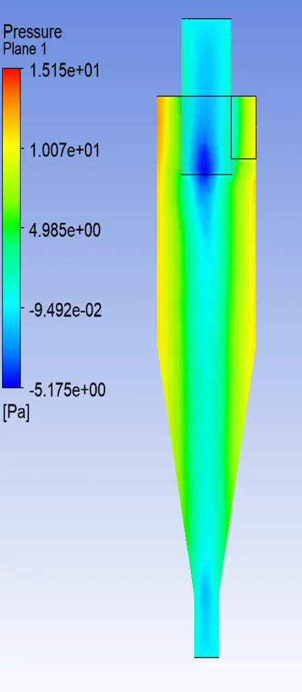
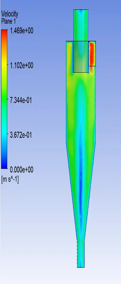
VELOCITY AND PRESSURE PLOT FOR 1M/S
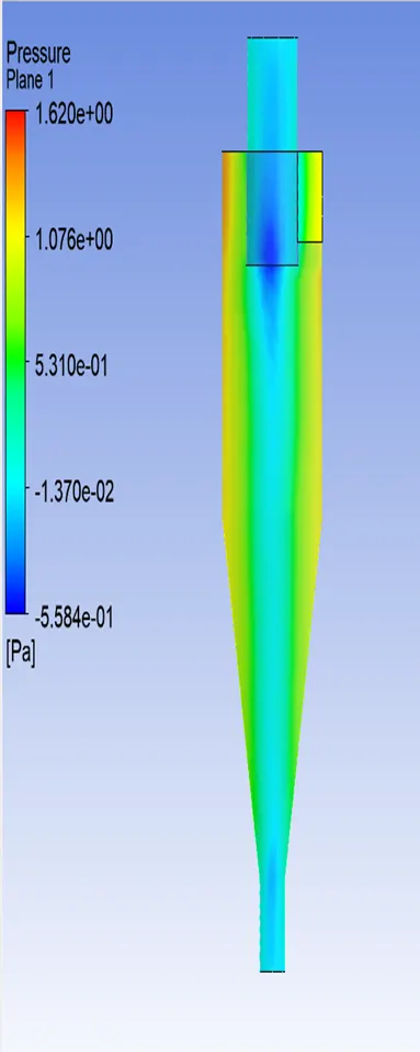
VELOCITY AND PRESSURE PLOT FOR 5M/S
Inference:
From the above pressure velocity plots, we can understand that the pressure is high at the walls of the cyclone separator. Due to high pressure on the walls the low pressure is region is created in the centre of the cylinder because of which the lighter particles escape from the top outlet and heavier particle are collected at the bottom outlet
Video depicting the particle size with constant velocity
Link For the Video:
https://drive.google.com/drive/folders/1qXqB6xwzSVvNEmTuTTqy3iI3rNDoIH_3?usp=sharing
In the above video, simulation is done properly and from residuals we can say the simulation is converged, we ran the simulation for 600 iteration and we can observe that the lighter particles also get trapped at the bottom outlet because of interaction between lighter and heavier particles and there is an exchange of inertial force between them as a result there is a transfer of kinetic energy from heavier particles to the lighter particle as the result we can observe a certain number of heavier particles escape through the top outlet.
EFFICIENCY CALCULATION:
Efficiency = No. of particles Trapped / (No. of particles injected – No. of Particle Incomplete)
|
Cases |
NO. of particles |
trap |
escape |
incomplete |
efficiency |
|
velocity = 5 partical size 5mic. |
378 |
305 |
64 |
9 |
82.6 |
|
velocity = 3 partical size 5mic |
378 |
141 |
164 |
73 |
46.22 |
|
velocity = 1 partical size = 5mic |
378 |
306 |
71 |
1 |
81.11 |
|
velocity = 1partical size = 3mic |
378 |
274 |
104 |
0 |
72.48 |
|
velocity = 3 partical size 3mic |
378 |
336 |
42 |
0 |
88.88 |
|
velocity=3 particle size = 1mic |
378 |
333 |
45 |
0 |
88.02 |
CONCLUSION:
The collection efficiency of cyclones caries as a function of particles size, density, and cyclone design. Cyclone efficiency will generally increase with the increase in particle size, density, inlet duct velocity, cyclone body length, number of gas revolutions in the cyclone, the ratio of cyclone body diameter to gas exit diameter, inlet dust loading, smoothness of the cyclone inner wall.
The efficiency of the cyclone will decrease with an increase in the parameters such as gas viscosity, cyclone body diameter, gas exit diameter, gas inlet duct area, gas density, leakage air into dust outlet.
With the increase in inlet velocity or particle size the efficiency increases
The collection efficiency of the cyclone separator is related to the pressure drop across the cyclone separator. Here pressure drop is the indirect measure of the energy required for the gas to move the particles. Pressure drop is related to the inlet velocity of air and particle size
Pressure Drop occurs because of the following components:
- Loss due to the expansion of gas in the cyclone chamber
- Loss due to rotational kinetic energy
- Loss due to wall frictional force