Simulating Cyclone separator with Discrete Phase Modelling
Abstract:
A CFD analysis of a cyclone separator is performed. The separation efficiency is found. Firstly the diameter of the particles is varied. Then the velocity at the inlet is varied with particles of constant diameter. The Physics of the problem is set up in Ansys Fluent. The Post-processing of the results obtained is done is CFD-Post.
Objective:
1. To perform an analysis on a given cyclone separator model by varying the particle diameter from `1mum` to `5mum` and calculating the separation efficiency in each case. Discuss the results. [Use both the velocities as 3m/sec
2. To perform an analysis on a given cyclone separator model by varying the particle velocity from 1 m/sec to 5 m/sec and calculating the separation efficiency and pressure drop in each case. Discuss the results. [Use particle diameter size as `5mum` for all cases & keep flow velocity the same as particle velocity]
Cyclone Separator: Cyclone separators are separation devices that use the principle of inertia to remove particulate matter from flue gases. A cyclone separator is one of many air pollution control devices known as pre-cleaners since they generally remove larger pieces of particulate matter. This prevents finer filtration methods from having to deal with large, more abrasive particles later on. In addition, several cyclone separators can operate in parallel, and this system is known as a multi-cyclone.
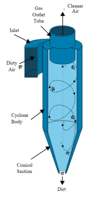
Cyclone separators work much like a centrifuge, but with a continuous feed of dirty air. In a cyclone separator, dirty flue gas is fed into a chamber. The inside of the chamber creates a spiral vortex, similar to a tornado. This spiral formation and the separation is shown in Figure. The lighter components of this gas have less inertia, so it is easier for them to be influenced by the vortex and travel up it. Contrarily, larger components of particulate matter have more inertia and are not as easily influenced by the vortex.
Since these larger particles have difficulty following the high-speed spiral motion of the gas and the vortex, the particles hit the inside walls of the container and drop down into a collection hopper. These chambers are shaped like an upside-down cone to promote the collection of these particles at the bottom of the container. The cleaned flue gas escapes out the top of the chamber.
Four empirical models were used to calculate the cyclone separator efficiency:
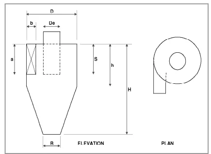
Figure: Tangential cyclone configuration
1. IOZIA AND LEITH MODEL
Iozia and Leith's (1990) logistic model is a modified version of Barth's (1956) model which is developed based on force
balance. The model assumes that a particle carried by the vortex endures the influence of two forces: a centrifugal force,
Z, and flow resistance, W. Core length, zc, and core diameter, dc, are given as
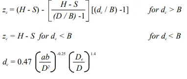
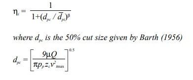
The addition made by Iozia and Leith on the original Barth (1956) model is the core length zc and slope parameter β expression which is derived based on the statistical analysis of experimental data of cyclone with D = 0.25 m. The collection
efficiency ηi of particle diameter dpi can be calculated from
2. LI AND WANG MODEL
The Li and Wang (1989) model include particle bounce or re-entrainment and turbulent diffusion at the cyclone wall. A two-dimensional analytical expression of particle distribution in the cyclone is obtained. Li and Wang's model was developed
based on the following assumptions:
• The radial particle velocity and the radial concentration profile are not constant, for uncollected particles within the
cyclones.
• Boundary conditions with the consideration of turbulent diffusion coefficient and particle bounce re-entrainment on
the cyclone wall are:
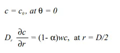
• The tangential velocity is related to the radius of the cyclone by:
`uR^n` = constant.
The concentration distribution in a cyclone is given as:
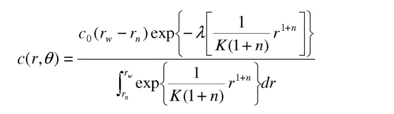
where
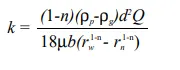
and
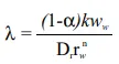
The resultant expression of the collection efficiency for particle
of my size is given as
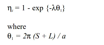
3. KOCH AND LICHT MODEL
Koch and Licht (1977) collection theory recognized the inherently turbulent nature of cyclones and the distribution of gas residence times within the cyclone. Koch and Licht describe particle motion in the entry and collection regions with the additional following assumptions:
• The tangential velocity of a particle is equal to the tangential velocity of the gas flow, i.e. there is no slip in the tangential direction between the particle and the gas.
• The tangential velocity is related to the radius of the cyclone by `uR^n` = constant.
A force balance and an equation on the particles collection yield the grade efficiency ηi.
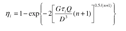
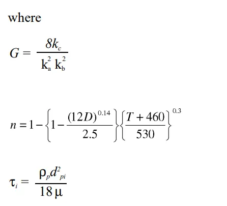
G is a factor related to the configuration of the cyclone, n is related to the vortex and `tau` is the relaxation term.
4. LAPPLE MODEL
Lapple's (1951) model was developed based on force balance without considering the flow resistance. Lapple assumed that a
particle entering the cyclone is evenly distributed across the inlet opening. The particle that travels from the inlet half-width to
the wall in the cyclone is collected with 50% efficiency. The semi-empirical relationship developed by Lapple (1951) to
calculate a 50% cut diameter, dpc, is
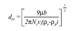
where `underset(e)(N)` is the number of revolutions
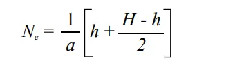
The efficiency of collection of any size of the particle is given by
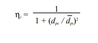
The collection efficiency of cyclones varies as a function of density, particle size and cyclone design. Cyclone efficiency will generally increase with increases in particle size and/or density; inlet duct velocity; cyclone body length; the number of gas revolutions in the cyclone; the ratio of cyclone body diameter to gas exit diameter; inlet dust loading; the smoothness of the cyclone inner wall.
Similarly, cyclone efficiency will decrease with increases in the parameters such as gas viscosity; cyclone body diameter; gas exit diameter; gas inlet duct area; gas density; leakage of air into the dust outlet. The efficiency of a cyclone collector is related to the pressure drop across the collector. This is an indirect measure of the energy required to move the gas through the system. The pressure drop is a function of the inlet velocity and cyclone diameter. From the above discussion, it is clear that small cyclones are more efficient than large cyclones. Small cyclones, however, have a higher pressure drop and are limited with respect to volumetric flow rates. Another option is to arrange smaller cyclones in series and/or in parallel to substantially increase efficiency at lower pressure drops. These gains are somewhat compensated, however, by the increased cost and maintenance problems. Also, these types of arrangements tend to plug in more easily. When common hoppers are used in such arrangements, different flows through cyclones can lead to re-entrainment problems.
ANALYSIS
Changing particle diameter from 1 micrometer to 5 micrometers, with a velocity of 3 m/s:
1. Geometry setup:
a. Choose the Fluid flow (fluent) module and start with editing geometry.
b. Import the step file of the model into Spaceclaim.
c. Fluid volume is extracted from the geometry by using the prepare option. so that we can analyze the fluid flow of the cyclone separator.
d. Hide the previous geometry and suppress physics since we are only interested in the fluid flow and not the external surface.
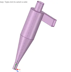
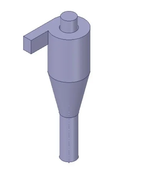
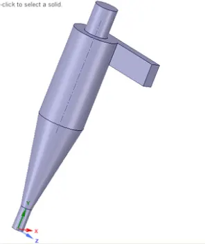
Figure: Pink geometry is the solid region (left) and the grey geometries are fluid regions prepared by using the volume extract tool in Ansys SpaceClaim.
2. Mesh setup:
Mesh stats:
1. Main element size: 9mm
2. Method = Cartesian method
3. Cartesian element size= 9 mm
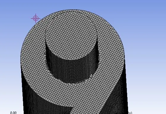
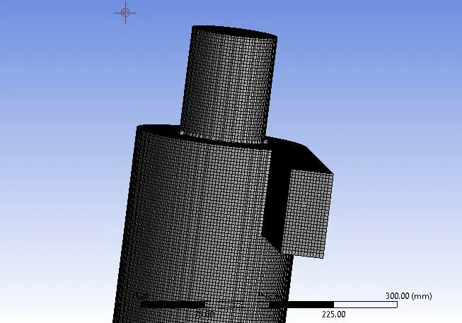
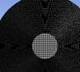
Cartesian Mesh
Named Selections
The face selecting tool is selected. The inlets, outlet (top) and outlet(bottom) are named. The inlet is through which the particles enter the lighter impurities escape through the top, and the heavier impurities are trapped in the bottom.
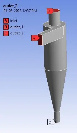
Solution Approach and Solver Requirement
1) General conditions:
This analysis involves the orientation of the cyclone separator. As it is in the x-y plane, the acceleration due to gravity needs to be turned on. As acceleration due to gravity acts upwards, the g value is assigned as -9.81 on the positive y-axis. Pressure based solver is used. The steady-state analysis is done and the velocity formulation is normal to the boundary and absolute.
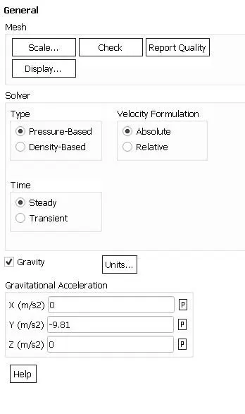 General Settings
2) Physics setup: Turbulence modeling: The K-epsilon(2 equation) model with RNG and swirl-dominated flow is selected. The wall modeling functions are standard wall functions.
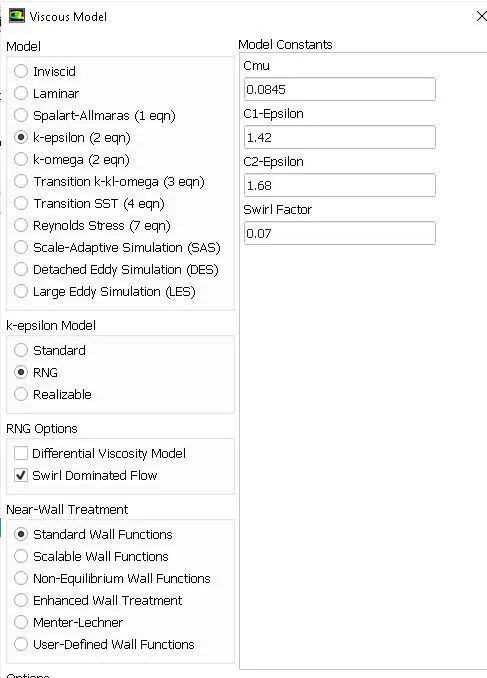
Viscous Model Settings
3) DPM
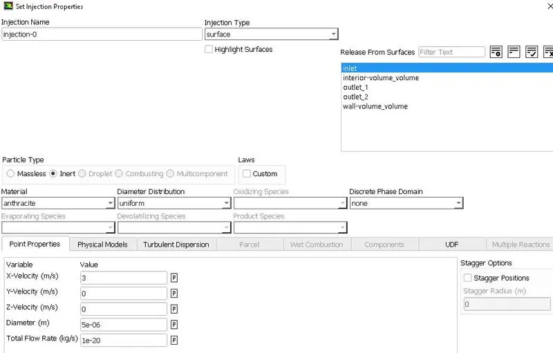
The model is enabled for interaction with the continuous phase. DPM interval level is 10. For injection, the particle type is inert. From the fluent database, anthracite is selected. It is released from the inlet, with velocity in the x-direction being 3m/s. This velocity may be manipulated further. The particle diameter chosen for the first analysis is one micrometer. The particle diameter is varied from one micrometer to five micrometers to calculate the separation efficiencies.
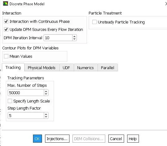
DPM Settings
4) Boundary conditions:
The boundary conditions are provided to three named selections, inlet, outlet(1)top and outlet(2) bottom.
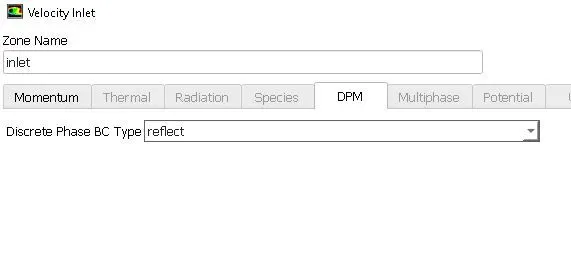
For the inlet, the momentum conditions are velocity is 3m/s in the x-direction, being absolute and normal to the boundary. The DPM condition is set to reflect. This signifies that the particles are not allowed to escape or get trapped in the inlet.
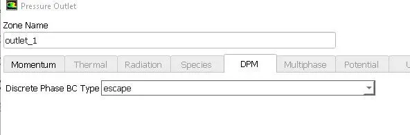
For the top outlet, the Momentum condition is the pressure condition, The DPM condition is set to escape. Particles can escape from this Boundary
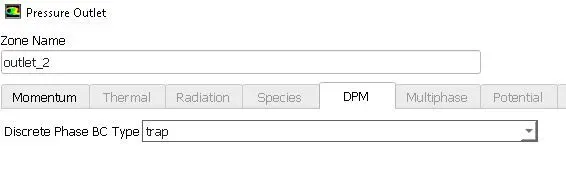
The bottom outlet is also a pressure outlet, with the DPM condition being trapped.
Here above all boundary conditions, we have given different DPM conditions like Reflect, Escape and Trap.
Reflect: It is the Particle Rebound off the boundary in question with a change in its momentum as defined by the coefficient of restitution.
Escape: The particle is reported as having “escaped”, when it encounters the boundary in question. Trajectories calculated are terminated.
Trap: The Trajectory calculated is terminated and the fate of the particle is recorded as “trapped”. In the case of evaporating droplets, their entire mass instantaneously passes into the vapor phase and enters the Cell adjacent to the boundary. IN the case of combusting particles, the remaining volatile mass is passed into the vapor phase.
5) Solution methods: The pressure velocity coupling is chosen as COUPLED scheme. The gradient is least-square cells based. Pressure, Momentum, Turbulent kinetic energy and turbulent dissipation rate are second-order upwind.
6) Initialization: Standard initialization is done with flow from inlets for 900 iterations.

7) Parametric Study:
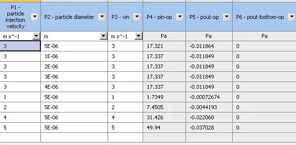
The parametric study is done for particle diameter and velocity at the inlet, in the first case particle size is varied from 1 micrometer to 5 micrometers while keeping the velocity as 3m/s and in the second case particle size is kept as 5 micrometers and inlet velocity is changed from 1m/s to 5m/s.
The particle injection velocity and the inlet velocity is kept equal for all analysis. All other boundary conditions, initialization and solution methods remain the same.
Parametric Study
8) Post-processing:
The data is exported from the fluent to CFD post to visualize the results. Opening CFD post, the particle history data is imported.
For the first case:
CASE 1
Analysis 1
v=3m/s and particle diameter is `5mum`.

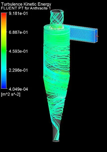
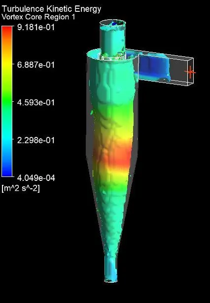
Contour plots are obtained for particle time, Eddy viscosity, swirl, pressure and Turbulent Kinetic Energy.
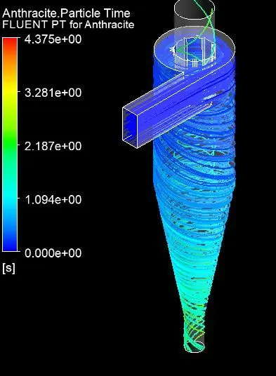
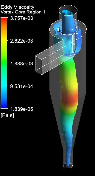
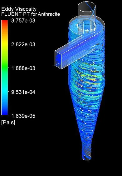
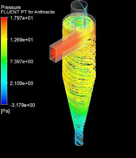
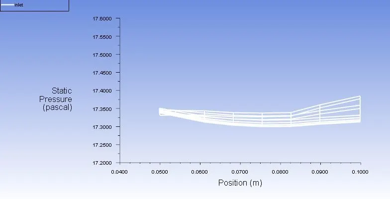
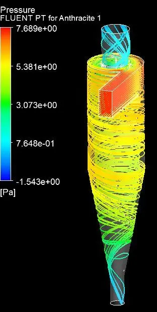
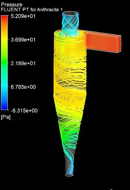
From the pressure plot, it can be inferred that the pressure is much higher at the inlets and lower at both outlets.
For further analysis, there is not much difference in the results for Contour plots.
Analysis 2
v=3m/s and particle diameter is `1mum`.

Analysis 3
v=3m/s and particle diameter is `2mum`.

Analysis 4
v=3m/s and particle diameter is `3mum`.

Analysis 5
v=3m/s and particle diameter is `4mum`.

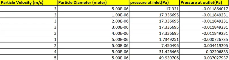
NOTE: The fluid velocity and particle velocity are 3m/sec for all particle sizes varied in Case-1. Therefore the pressure drop remains constant for all analyses of case-1.
CASE 2
In this analysis, velocity is varied from 1 to 5 m/s while particle diameter is kept as `5mum`.
Analysis 1
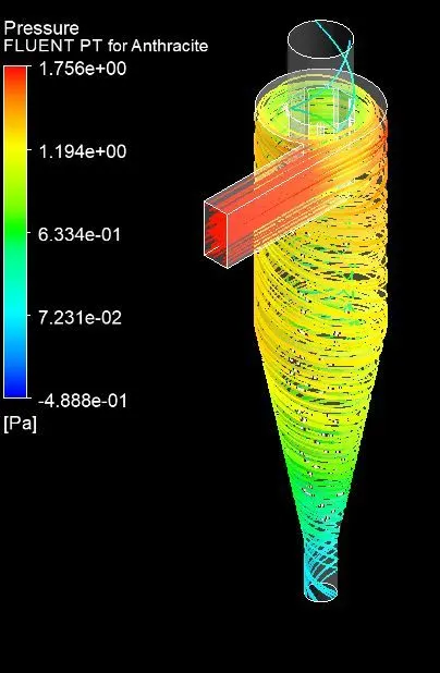
v=1m/s and particle diameter is `5mum`.

Analysis 2
v=2m/s and particle diameter is `5mum`.

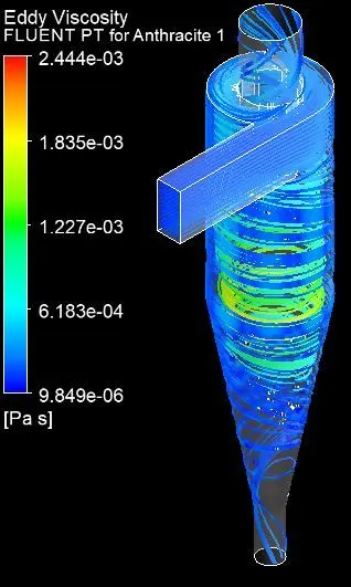
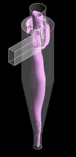
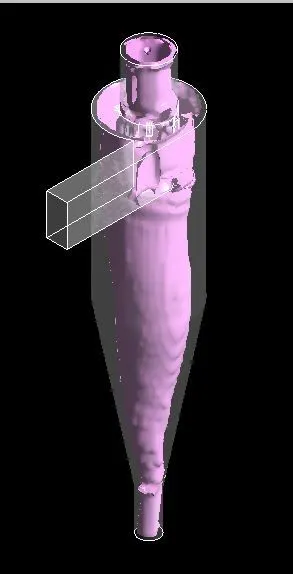
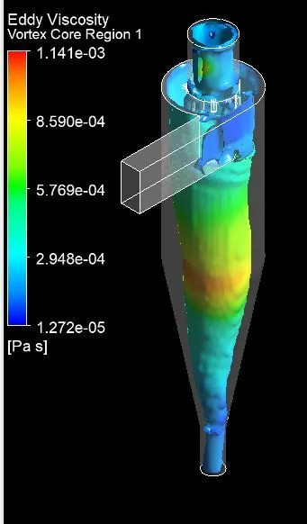
Swirls are shown with swirl levels of 0.34386 and 0.072. The eddy viscosity is more at the core region due to higher rotational speeds.
Analysis 3
v=4m/s and particle diameter is `5mum`.
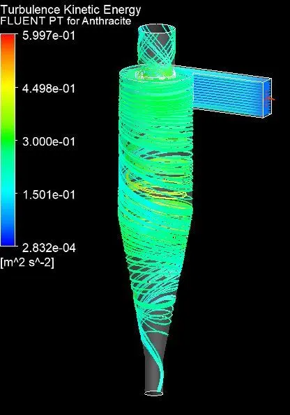
Analysis 3
v=4m/s and particle diameter is `5mum`.
9) Results
From the obtained results Separation efficiency and pressure drop are studied.
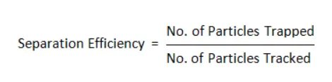
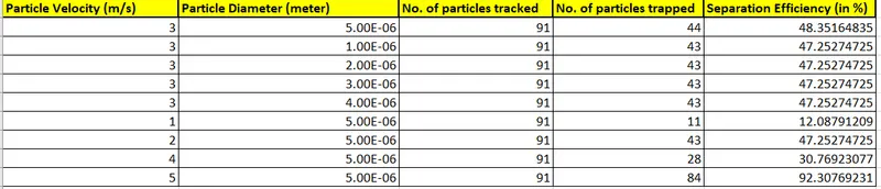
Separation efficiency: It is defined as the fraction of particles of a given size collected in the cyclone, compared to those of that size going into the cyclone. Experience shows that the separation efficiency of cyclone separator increases with increasing particle mean diameter and density; increasing gas tangential velocity; decreasing cyclone diameter; increasing cyclone length; extraction of gas along with solids through the cyclone legs. In this case, depending upon the particle history data - Separation Efficiency is defined as the ratio of concentration that has been removed from the feed stream to the initial concentration in the feed stream. For this case ratio of the number of trapped particles to the total number of particles tracked.
Pressure Drop: Pressure drop across the cyclone is of much importance in a cyclone separator. The pressure drop significantly affects the performance parameters of a cyclone. The total pressure drop in a cyclone will be due to the entry and exit losses, and friction and kinetic energy losses in the cyclone. Normally the most significant pressure drop occurs in the body due to swirl and energy dissipation. Pressure drop is defined as the difference in total pressure between two points of a fluid-carrying network.
Pressure drop = Total inlet pressure - Total Outlet Pressure
As the “escape” DPM condition is given to the outlet-top in this case, so outlet-top is considered in the pressure drop calculation.
The calculation was done in excel and the results are shown below.
Conclusion
- From the above pressure velocity plots, we can infer that the pressure is higher near the wall region which forms the outer vortex.
- Due to higher pressure near the wall low-pressure region is created at the center of the cyclone separator because of which the lighter particles escape from the top outlet and heavier particles are collected at the bottom outlet.
- Simulation is done for particle size varying from 1μm to 5μm with air and particle velocity as 3m/s.
- From the results, it is observed that heavier particle is trapped at the bottom outlet and lighter particles are escaped at outlet 1. But we can also see that lighter particles also get trapped at the bottom outlet because of interaction between lighter and heavier particles and there is an exchange of inertial forces between them as a result there is a transfer of Kinetic energy from heavier particle to the lighter particle, as a result, we can observe a certain number of heavier particles escapes through the top outlet.
- The collection efficiency of cyclones varies as a function of particle size, density, and cyclone design. Cyclone efficiency will generally increase with the increase in particle size, density, inlet duct velocity, cyclone body length, number of gas revolutions in the cyclone, the ratio of cyclone body diameter to gas exit diameter, inlet dust loading, smoothness of the cyclone inner wall.
- The efficiency of the cyclone will decrease with an increase in the parameters such as gas viscosity, cyclone body diameter, gas exit diameter, gas inlet duct area, gas density, and leakage of air into the dust outlet. With the increase in inlet velocity or particle size the efficiency increases.
- The collection efficiency of the cyclone separator is related to the pressure drop across the cyclone. Here pressure drop is the indirect measure of the energy required for the gas to move the particles. Pressure drop is related to the inlet velocity of air and particle size.
Pressure drop occurs because of the following components:
1. Loss due to the expansion of gas in the cyclone chamber.
2. Loss due to rotational kinetic energy.
3. Loss due to wall frictional forces