Week 8 - Simulating Cyclone separator with Discrete Phase Modelling
Simulating Cyclone separator with Discrete Phase Modelling
Aim:- To perform analysis on cyclone separator and calculate the separation efficiency and pressure drop.
Cyclonic separator
Cyclonic separation is a method of removing particulates from an air, gas, or liquid stream, without the use of filters, through vortex separation. Rotational effects and gravity are used to separate mixtures of solids and fluids.
A high-speed rotating (air) flow is established within a cylindrical or conical container called a cyclone Air flower in a helical pattern, beginning at the top (wide end) of the cyclone and ending at the bottom (narrow) eny before exting the cyclone in a straight stream through the center of the cyclone and out the top. Larger (denser) particles in the rotating stream have too much inertia to follow the tight curve of the stream, and thus strike the outside wall, thenfall to the bottom of the cyclone where they can be removed. In a conical system, as the rotating flow moves towards the narrow end of the cyclone, the rotational radius of the stream is reduced, thus separating smaller and smaller particles. The cyclone geometry, together with the volumetric flow rate, defines the cut point of the cyclone. This is the size of particle that will be removed from the stream with a 50% efficiency. Particles larger than the cut point will be removed with greater efficiency and smaller particles with a lower efficiency as they separate with more difficulty or can be subject to re-entrainment when the air vortex reverses direction to move in direction of the outlet.
Cyclone separator working:
Cyclone separators work much like a contrifuge, but with a continuous feed of dirty air, in a cyclone separator, dirty flue gas is fed into a chamber. The inside of the chamber creates a spiral vortex, similar to a tornado. The lighter components of this gas have less inertia, so it is easier for them to be influenced by the vortex and travel up it Contrarily, larger components of particulate matter have more inertia and are not as easily influenced by the vortex.
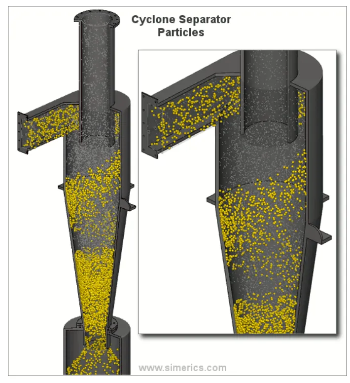
Since these farger particles have difficulty following the high-speed spiral motion of the gas and the vortex the particles hit the inside walls of the container and drop down into a collection hopper. These chambers are shaped liko an upside down cone to promote the collection of these particles at the bottom of the container. The cleaned flue gas escapes out the top of the chamber.
To write a few words about any four empirical models used to calculate the cyclone separator efficiency?
IOZIA AND LEITH MODEL
lozia and Leith (1990) logistic model is a modified version of Barth (1956) model which is developed based on force balance. The model assumes that a particle carried by the vortex endures the influence of two forces: a centrifugal force and a flow resistance.
LI AND WANG MODEL
The Li and Wang (1989) model includes particle bounce or re-entrainment and turbulent diffusion at the cyclone wall. A two-dimensional analytical expression of particle distribution in the cyclone is obtained. Li and Wang model was developed based 180 on the assumption that the radial particle velocity and the radial concentration profile are not constant for uncollected particles within the cyclone.
KOCH AND LICHT MODEL
Koch and Licht (1977) collection theory recognized the inherently turbulent nature of cyclones and the distribution of gas residence times within the cyclone. Koch and Licht describe particle motion in the entry and collection regions with the assumption that The tangential velocity of a particle is equal to the tangential velocity of the gas flow, Le. there is no slip in the tangential direction between the particle and the gas.
LAPPLE MODEL
Lapple (1951) model was developed based on force balance without considering the flow resistance. Lapple assumed that a particle entering the cyclone is evenly distributed across the inlet opening. The particle that travels from inlet half width to the wall in the cyclone is collected with 50% efficiency.
To perform an analysis on a given cyclone separator model by varying the particle diameter from 1 μm to 5 μm and calculate the separation efficiency in each case. Discuss the results. [Use both the velocity's as 3m/sec.]
Set up the geomerty
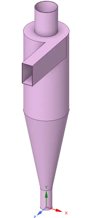
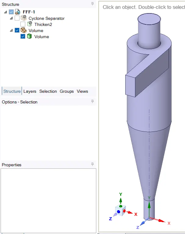
Extracting volume
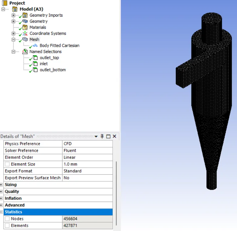
Meshing
Calculating the efficiency of a cyclone separator
(Case1 5e-6 with constant velocity 3m/s)
Case setup
Double Precision, Solve processers = 2
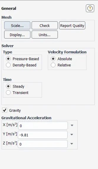
Solver
Type Pressure Based
• Velocity Formulation Absolute.
Steady
3. Gravity - on
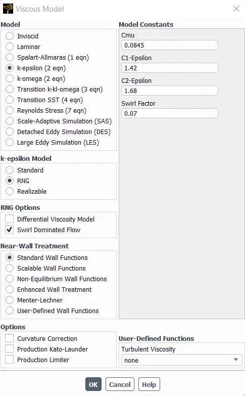
Turbulance Module
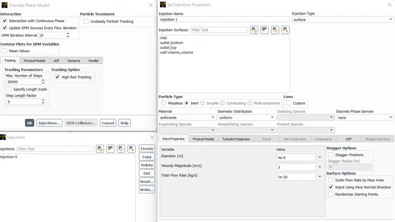
Injections => create
Name = anthracite injection
Type = Surface injection
Relese from => Inlet
Material => anthracite
Point Properties
Injection using face normal point
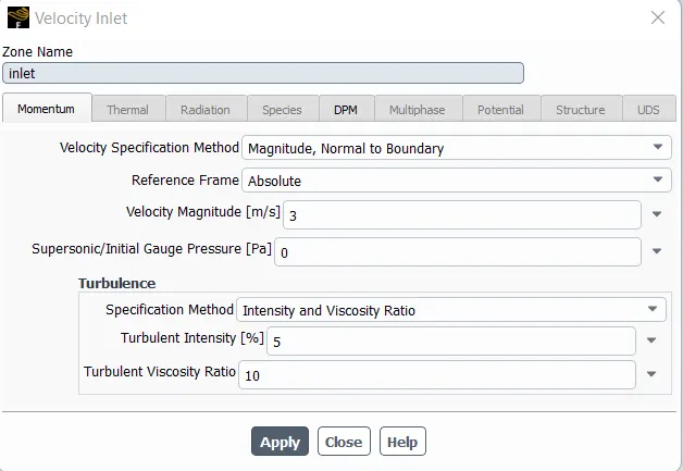
Boundary Conditions:-
Inlet and wall:- Reflect
Outlet(Top):- Escape
Outlet(Bottom/dustbin) - Trap
Pressure velocity coupling method
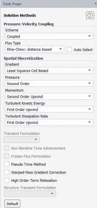
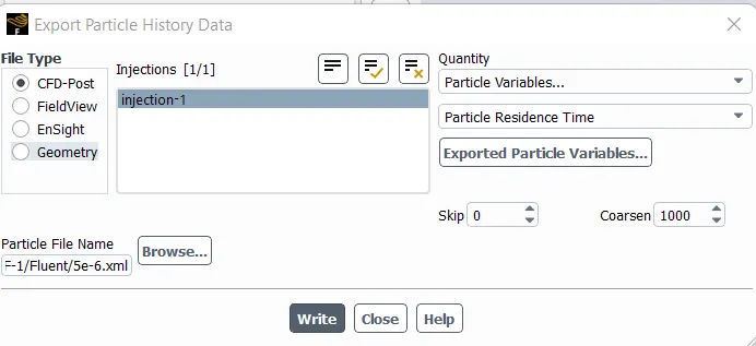
Export the soluction for the post processor
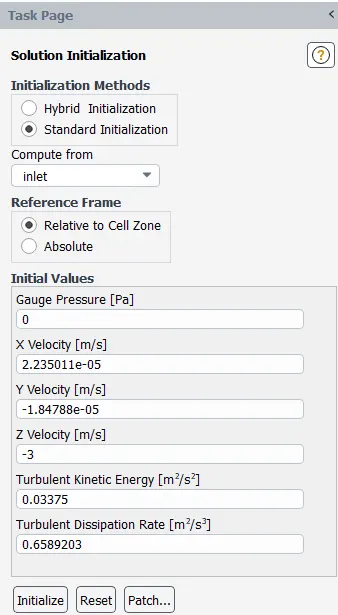
Run the inilatzation with standard method
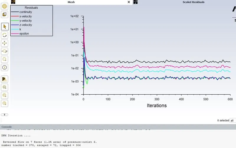
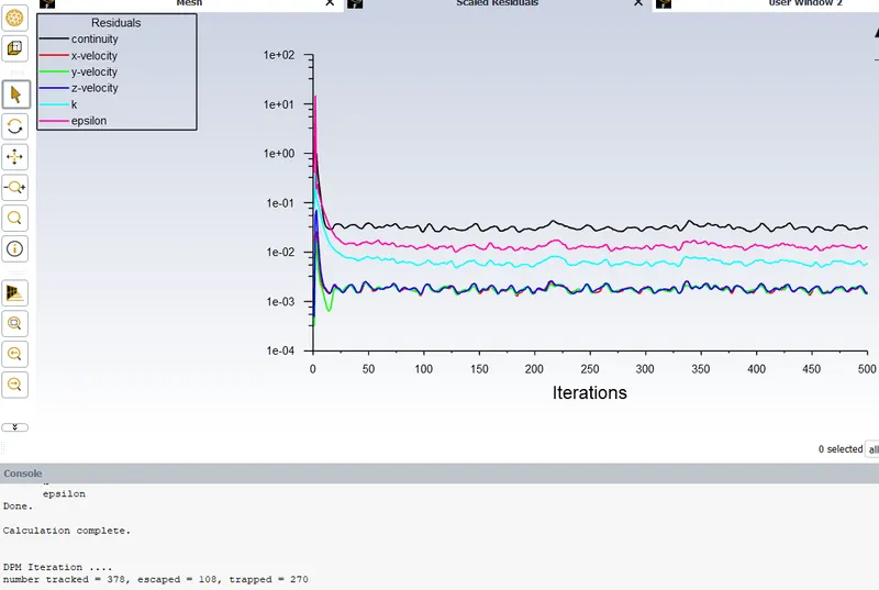
Run the simulation for 600 iterations
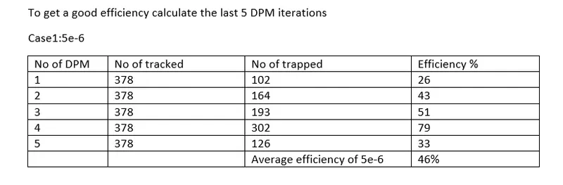
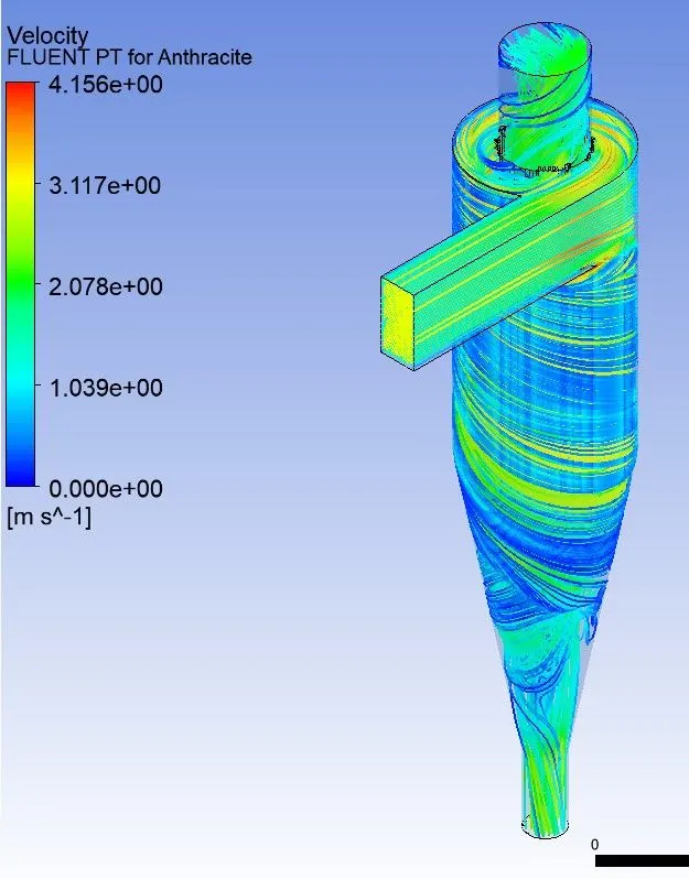
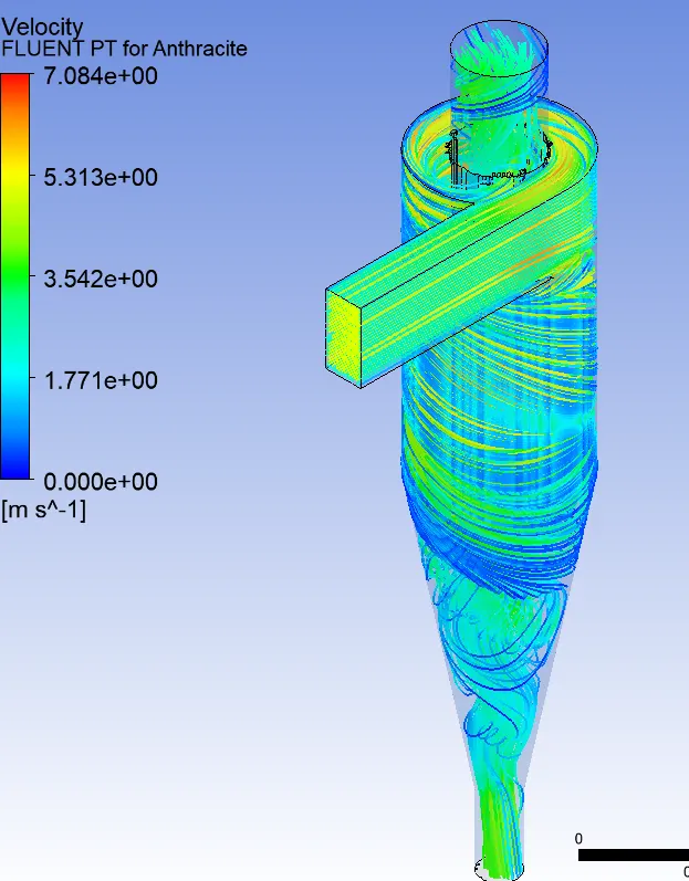
Results: case1 5e-6
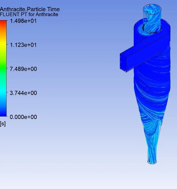
YOU TUBE link for animation
we got the efficiency of 46%

Case2 4e-6
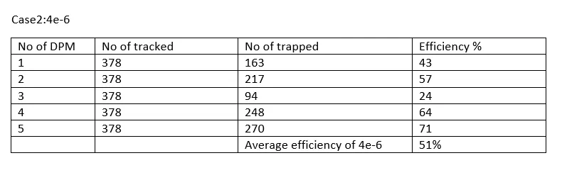
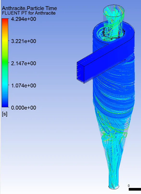
YOU TUBE link for animation
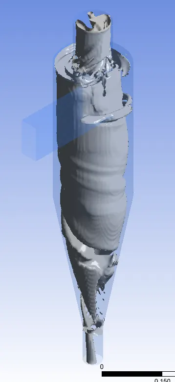
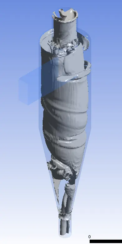
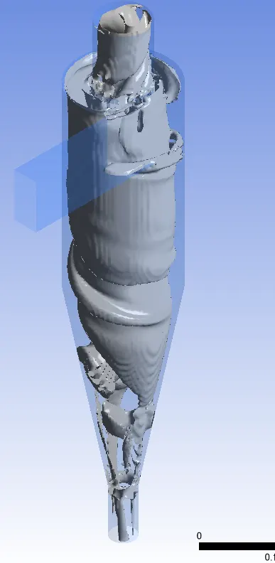
Voetex core region
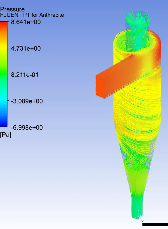
Case3 : 3e-6
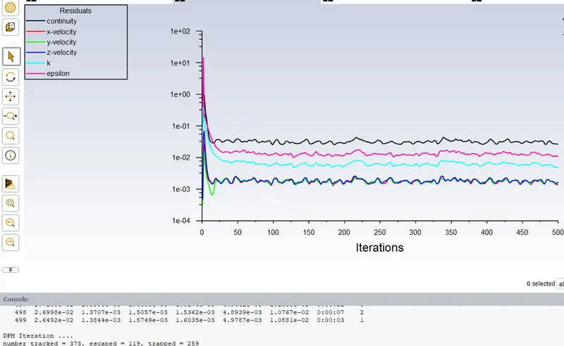
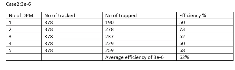
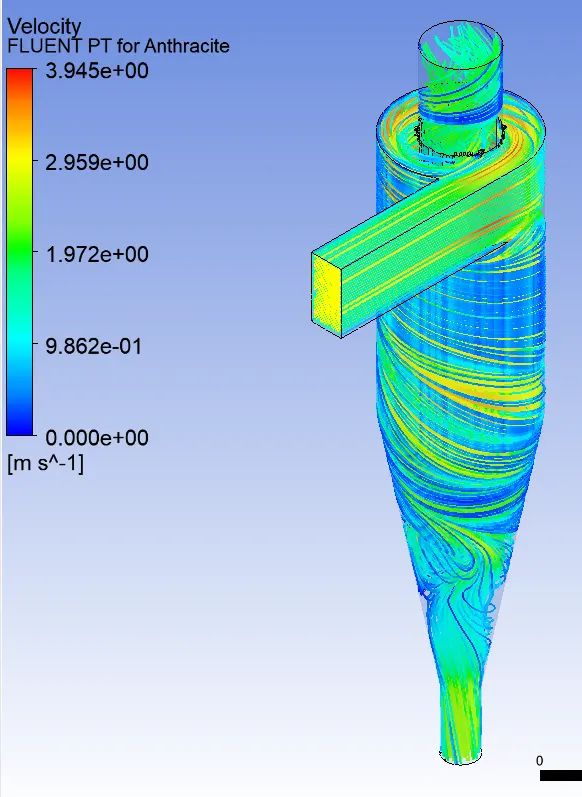
Case 4 : 2e-6
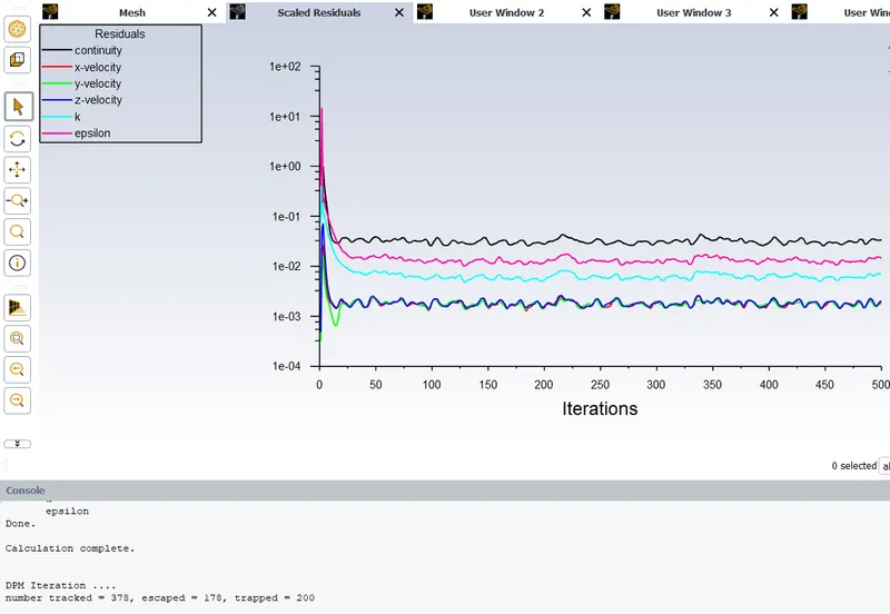
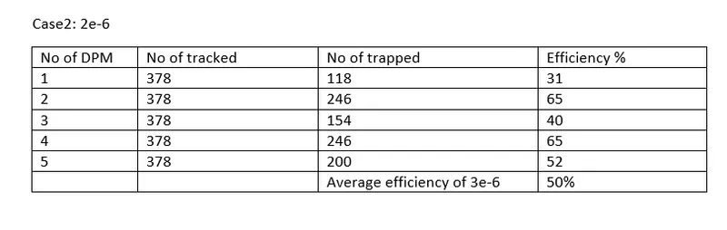
YOU TUBE link for animation
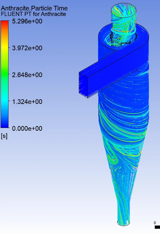
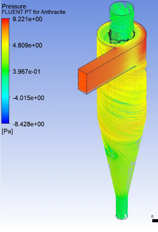
Case5 :1e-6
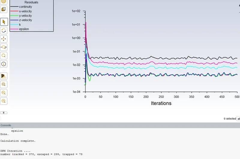
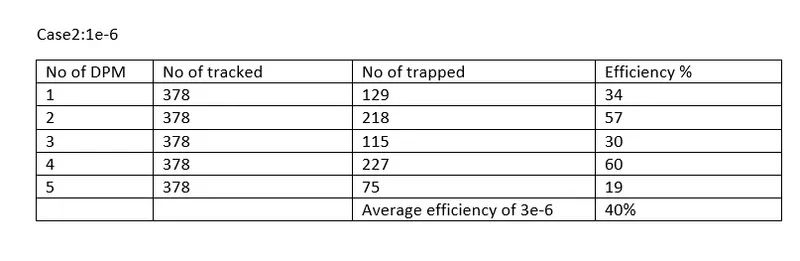
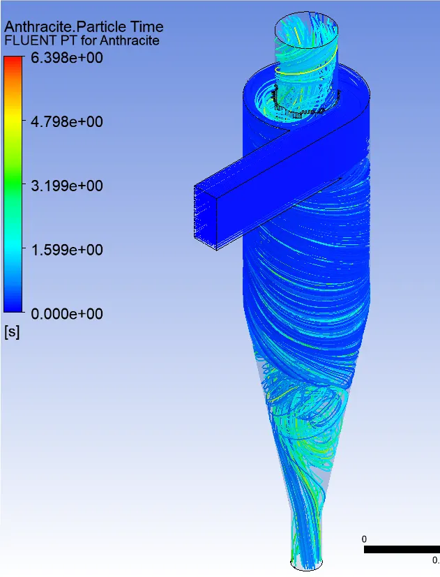
YOU TUBE link for animation
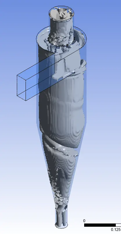
To perform an analysis on a given cyclone separator model by varying the particle velocity from 1 m/sec to 5 m/sec and calculate the separation efficiency and pressure drop in each case. Discuss the results. [Use particle diameter size as 5 μm for all cases & keep flow velocity same as particle velocity]
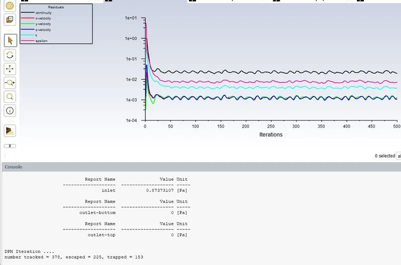
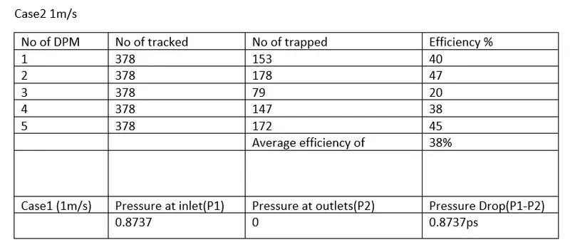
Case2 : 1m/s velocity
YOU TUBE link for animation
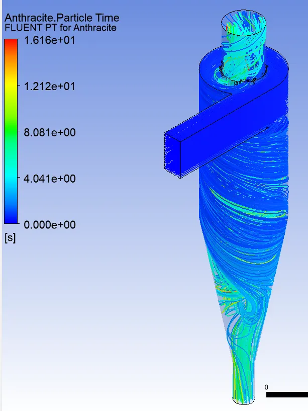
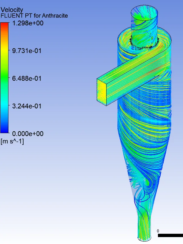
Case2 (2m/s)
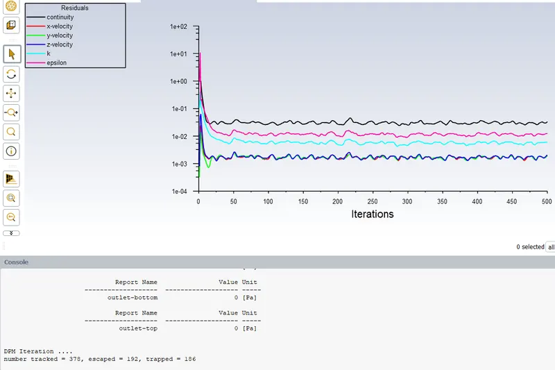
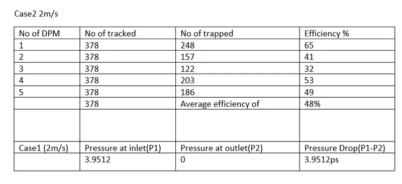
YOU TUBE link for animation
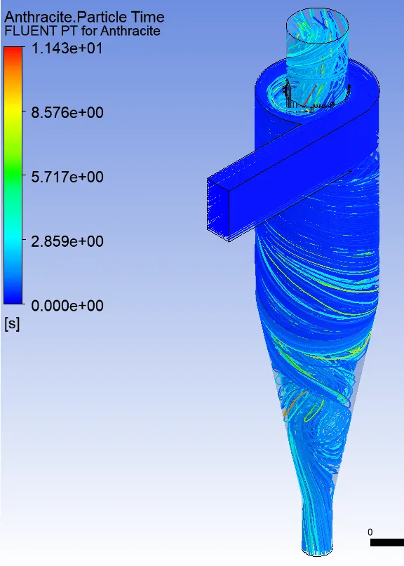
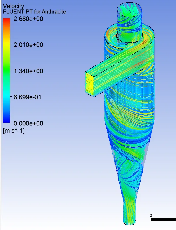
Case3 (m/s)
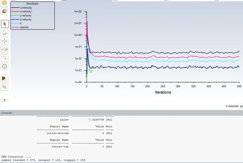
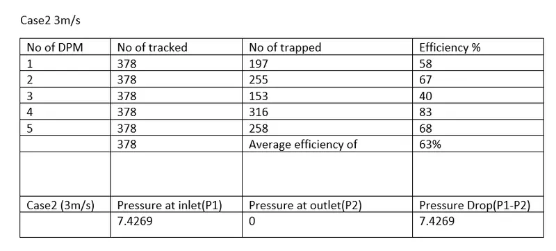
YOU TUBE link for animation
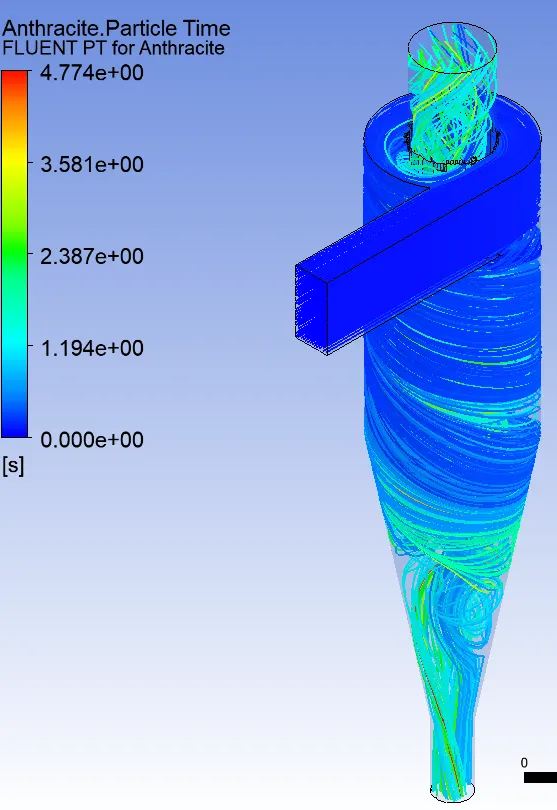
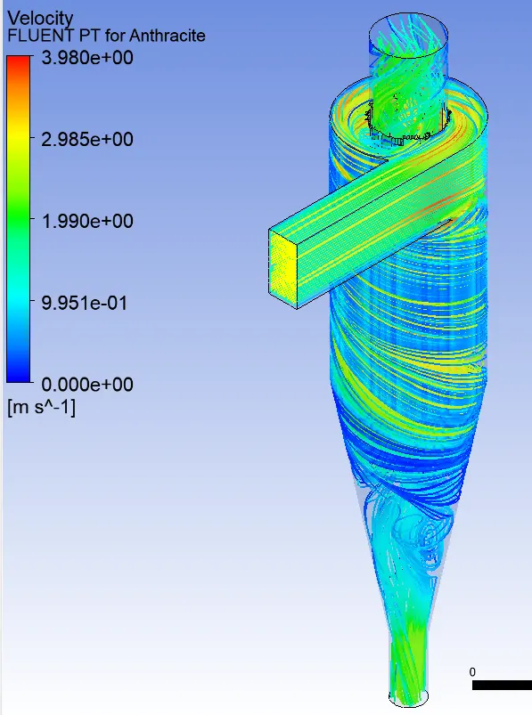
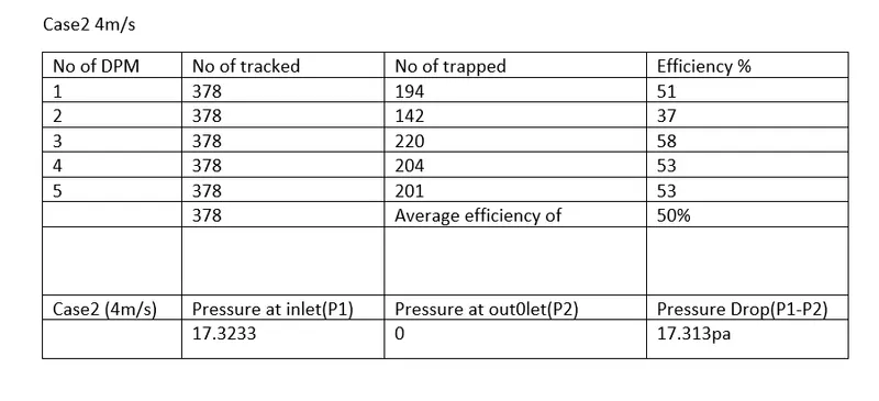
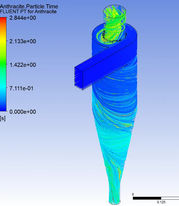
Case2 (4m/s)
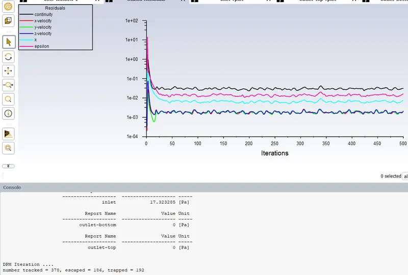
YOU TUBE link for animation
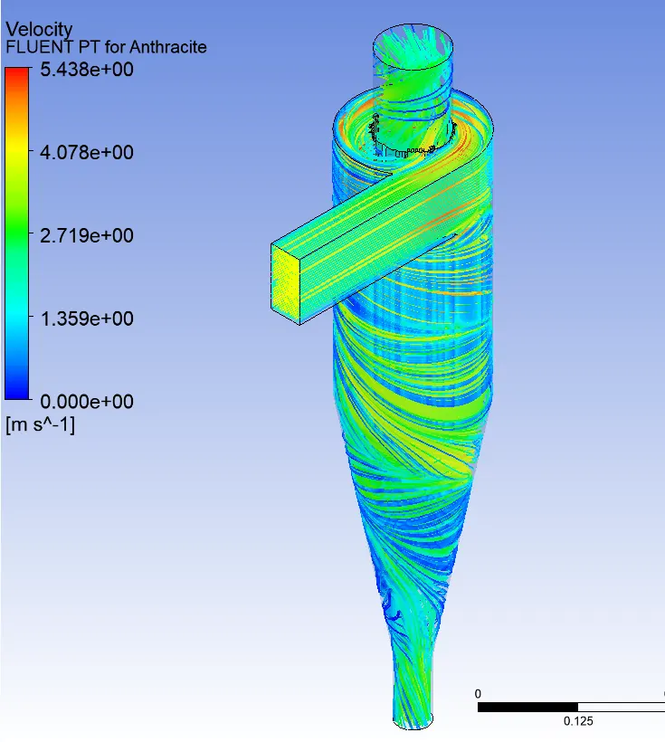
Case 2 (5m/s)
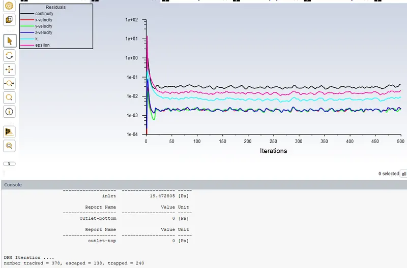
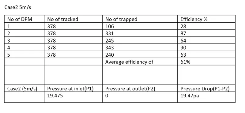
YOU T UBE link for animation
Conclusion :
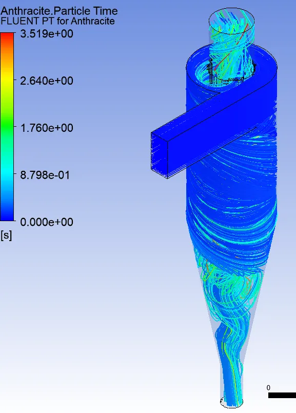
Particles with a size exceeding a critical diameter, which may depend on cyclone geometry and flow condition, will not be collected at the cyclone bottom and may stagnate on the conical wall of the cyclone as a result of the balanced forces such as the supporting force from the wall, the gas drag force and the gravity force. This may lead to the formation of the permanent deposition on the conical part in the cyclone.
The separation efficiency increases with increase in particle size. because the particle with more mass will have more gravitational force to get settle down at the outlet 2.
The pressure drops remains constant for the particles with same velocity, because the pressure drop is afunction of velocity of the particles.
The separation efficiency increases with increase in velocity of particle.
The pressure drop increases with increase in particle velocity, because the pressure drop is a function of velocity of the particles.
****************************************************************************************************************************