Week 8 - Simulating Cyclone separator with Discrete Phase Modelling
Aim: To perform analysis on cyclone seperator by simulating it in Ansys Fluent and calculating the seperation efficiency and pressure drop.
Cyclone seperator:
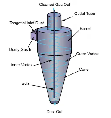
Cyclone separators provide a method of removing particulate matter from air or other gas streams at low cost and low maintenance. Cyclones are somewhat more complicated in design than simple gravity settling systems, and their removal efficiency is much better than that of settling chamber. Cyclones are basically centrifugal separators, consists of an upper cylindrical part referred to as the barrel and a lower conical part referred to as cone. They simply transform the inertia force of gas particle flows to a centrifugal force by means of a vortex generated in the cyclone body. The particle laden air stream enters tangentially at the top of the barrel and travels downward into the cone forming an outer vortex. The increasing air velocity in the outer vortex results in a centrifugal force on the particles separating them from the air stream. When the air reaches the bottom of the cone, it begins to flow radially inwards and out the top as clean air/gas while the particulates fall into the dust collection chamber attached to the bottom of the cyclone.
1.Iozia and Leith Model
Iozia and Leith logistic model is a modified version of Barth Model, which is developed based on force balance.
The model assumes that a particle carried by the vortex endures 165 the influence of two forces: a centrifugal force, Z and a flow resistance, W. The collection efficiency ηi of particle diameter dpi can be calculated from
`ηi =1/(1 + ( (dpc)/(dpI) )^β )`
β is an expression for slope parameter derived based on the statistical analysis of experimental data of a cyclone with D =0.25 m given as

and dpc is the 50% cut size given by Barth
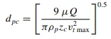
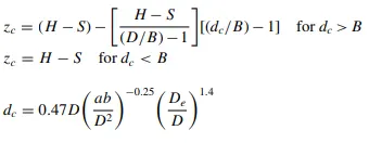
where core length, zc, and core diameter, dc, are given as
2.Koch and Licht Model
Koch and Licht collection theory recognized the inherently turbulent nature of cyclones and the distribution of gas
residence times within the cyclone. Koch and Licht described
particle motion in the entry and collection regions with the additional following assumptions:
• The tangential velocity of a particle is equal to the tangential velocity of the gas flow, i.e. there is no slip in the tangential direction between the particle and the gas.
• The tangential velocity is related to the radius of cyclone by: u Rn = constant
A force balance and an equation on the particles collection yields
the grade efficiency ηi
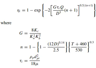
G is a factor related to the configuration of the cyclone, n is related to the vortex and τ is the relaxation term
3.Lapple Model
Lapple model was developed based on force balance without considering the flow resistance. Lapple assumed that a par215 ticle entering the cyclone is evenly distributed across the inlet opening. The particle that travels from inlet half width to the wall in the cyclone is collected with 50% efficiency. The semi empirical relationship developed by Lapple to calculate a 50% cut diameter, dpc, is
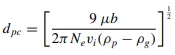
Where Ne is the number of revolution,
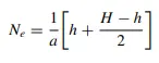
The efficiency of collection of any size of particle is given by
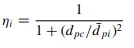
4. Li and Wang Model
The Li and Wang model includes particle bounce or reentrainment and turbulent diffusion at the cyclone wall. A twodimensional analytical expression of particle distribution in the cyclone is obtained. Li and Wang model was developed based on the following assumptions:
• The radial particle velocity and the radial concentration profile are not constant for uncollected particles within the cyclone.
• Boundary conditions with the consideration of turbu185 lent diffusion coefficient and particle bounce reentrainment on the cyclone wall are:
c=c0, at theta=0
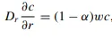
where r=D/2
• The tangential velocity is related to the radius of cyclone by: u Rn = constant.
The concentration distribution in a cyclone is given as:
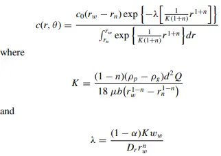
The resultant expression of the collection efficiency for particle
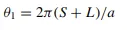
of any size is given as

where,
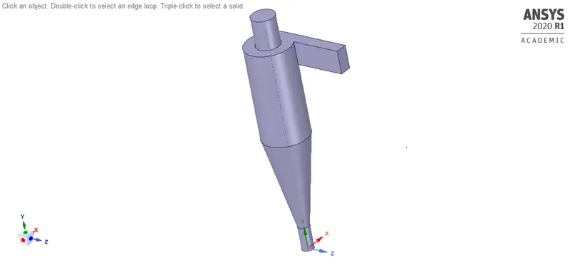
Geometry:
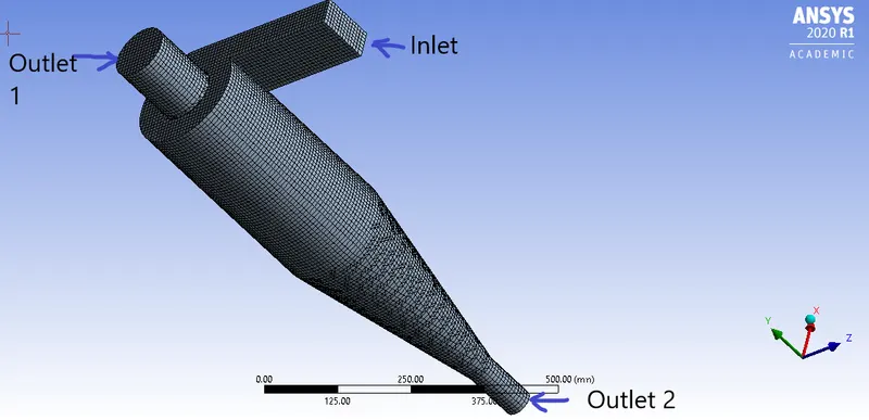
The geometry file is prepared using spaceclaim as we need to extract volume which is under our consideration.
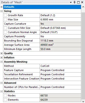
Meshing:
For meshing we have used cutcell method in order to generate structured grid automatically while meshing and we get a hexahedron mesh.
Solution setup:
Solver= pressure based
Velocity formulation=Absolute
simulation time= steady state
Gravity=y axis=-9.81 m/s
Solution model:
k-ε RNG model, swirl dominated flow
It is good for moderately complex behavior like jet.impingement, separating flows, swirling flows, and
secondary flows but,Subjected to limitations due to isotropic eddy viscosity assumption.
Discrete phase modeling:
In this simulation we have learned to use DPM approach in simulation.DPM is used when you want to model solid particles in liquid or liquid in gas or bubble in water.
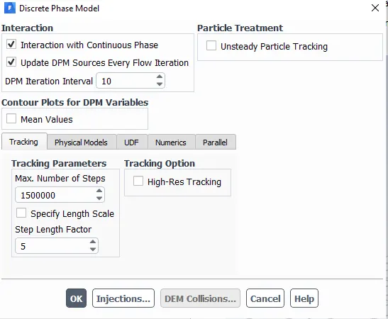
We turned interaction with continous phase on, as we need to get a coupled flow. Further, DPM source is updated for each flow iteration as it gives chance to calculate particle source terms at every iteration.
The DPM iteration interval is set to 10, at it allows you to control frequency at which the particles are trapped.
Max number of steps=1500000, this is thenumber of steps required to track trajectory of a single paricle.
Step length factor=5, larger the step length smaller is the time step.
Injection properties:
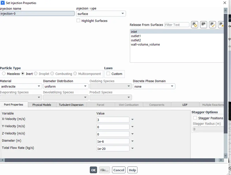
The particle velocity =x-velocity is set according to given conditions, so is the diameter of particle.
Material is anthracite and its paticles are released from inlet.
Boundary conditions:
Inlet= velocity=5m/s to 1m/s for different cases
DPM= discrete phase boundary condition=Reflect
Outlet1= pressure outlet
DPM= discrete phase boundary condition=Escape
Outlet2= pressure outlet
DPM= discrete phase boundary condition=Trap
Initialization:
Standard initialization=inlet
Calcuation:
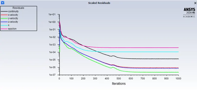
No.of iteration=1000,Time scalar factor=1
Case 1) varying particle diameter and keeping particle velocity constant at 5m/s
A) Inlet velocity=3m/s, particle velocity=3m/s
Particle diameter=1e-6
Residual plot:
Anthracite particle time:
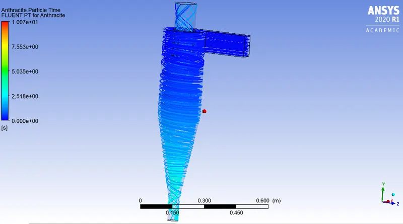

Separator efficiency=(particle trapped/particle tracked)*100=(58/98)*100=59.18%
B) Inlet velocity=3m/s, particle velocity=3m/s
Particle diameter=2e-6
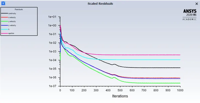
Residual plot:
Anthracite particle time:
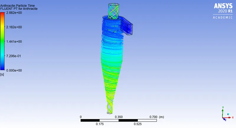

Separator efficiency=(particle trapped/particle tracked)*100=(64/98)*100=65.30%
C) Inlet velocity=3m/s, particle velocity=3m/s
Particle diameter=3e-6
Residual plot:
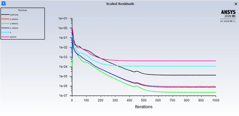
Anthracite particle time:
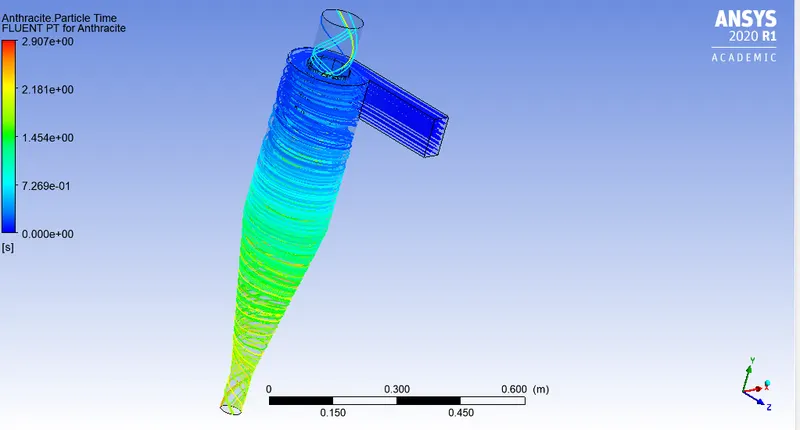

Separator efficiency=(particle trapped/particle tracked)*100=(75/98)*100=76.53%
D)Inlet velocity=3m/s, particle velocity=3m/s
Particle diameter=4e-6
Residual plot:
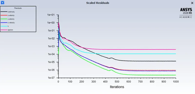
Anthracite particle time:
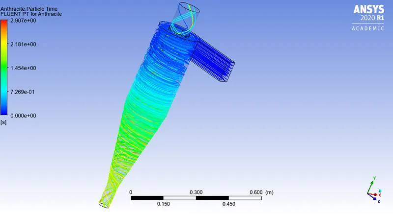

Separator efficiency=(particle trapped/particle tracked)*100=(86/98)*100=87.75%
E)
Inlet velocity=3m/s, particle velocity=3m/s
Particle diameter=5e-6
Residual plot:
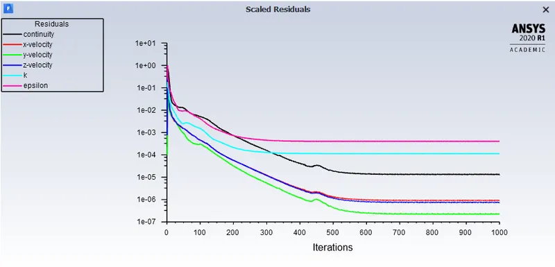
Anthracite particle time:
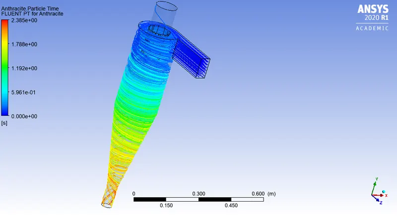

Separator efficiency=(particle trapped/particle tracked)*100=(97/98)*100=98.97%
Conclusion: The above results show that cyclone seperator is more efficient to trap larger diameter particles as compared to smaller particles. Particle size of 5 micrometer is most effciently seperated, while only 50 percent particles of size 1 micrometer is trapped.
Case2) Varying particle velocity and keeping particle diameter(5e-6m) same for all the cases.
(particle velocity and inlet velocity is equal)
we have to find pressure drop in each case, the pressure drop is the difference between inlet pressure and outlet pressure of cyclone seperator.Pressure drop across the cyclone is of much importance in a cyclone separator. The pressure drop significantly affects the performance parameters of a cyclone.
A) particle velocity = inlet velocity = 1m/s
Residual:
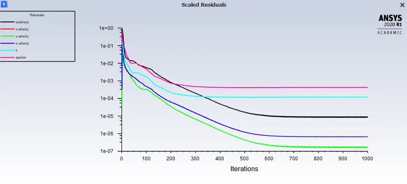

Seperation efficiency:
(92/98)*100=93.877
Pressure drop:
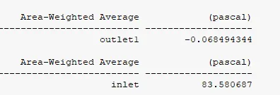
Pressure drop=inlet pressure-outlet pressure=83.58-(-0.068494)=83.6484
Anthracite particle time:
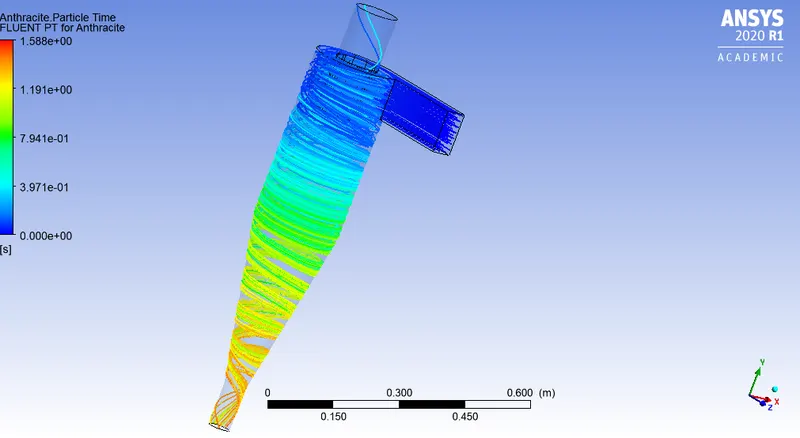
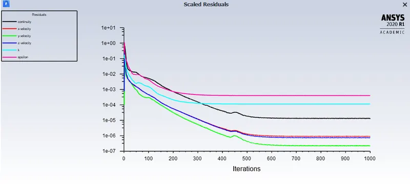
B) particle velocity = inlet velocity = 3m/s
Residual:

Seperation efficiency:
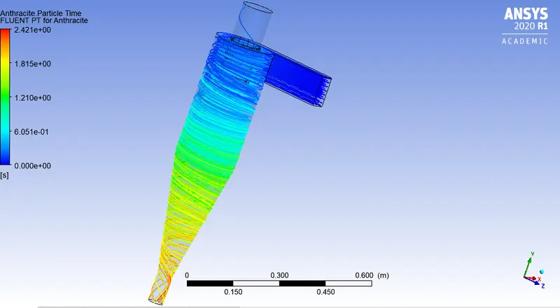
(97/98)*100=98.97%
Pressure drop:
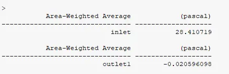
Pressure drop=inlet pressure-outlet pressure=28.4107-(-0.02059)=28.43
Anthracite particle time:
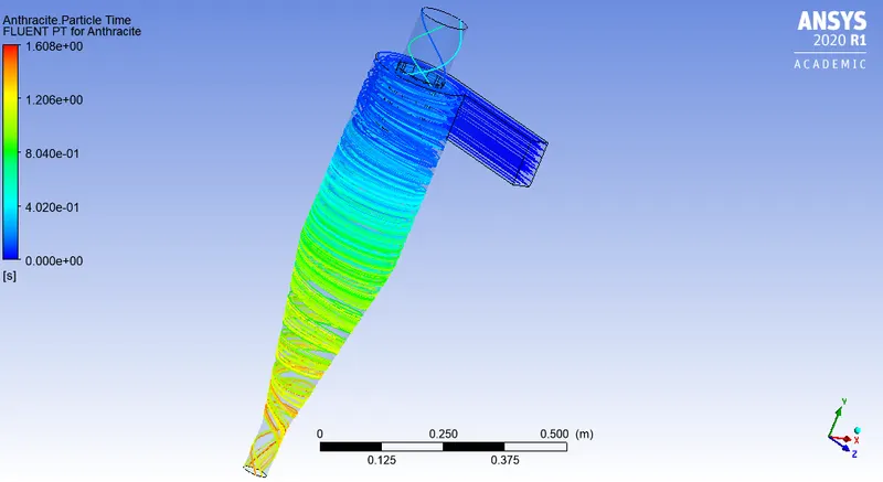
C) particle velocity = inlet velocity = 5m/s
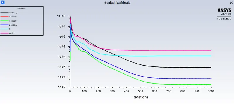
Residual:

Seperation efficiency:
(91/98)*100=92.85%
Pressure drop:
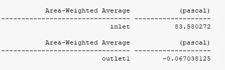
Pressure drop=inlet pressure-outlet pressure=83.5802-(-0.06703)=83.647
Anthracite particle time:
Resulr:
1)The larger paricles gets seperated more efficiently as compared to smaller particles dispersed in fluid as they are more denser and gets setteled at the bottom.
2)While the particles seperation efficiency is i=also influenced by velocity at which the particles are introduced in seperator as we have seen in case 2, that efficieny at velocity of 1m/s was good but it got much better at 3m/s but, only to decrease at 5 m/s.
3) The pressure drop shows that it increases as the particle velocity increases with increase in seperation efficiency.
4) The Case1 and case 2 shows that efficiency of cyclone seperator is dependent on both diameter of the particle and particle velocity.
Reference:
file:///C:/Users/dell/Downloads/IJCMESM_proof.pdf
https://nptel.ac.in/content/storage2/courses/103103027/pdf/mod5.pdf