Week 8 - Simulating Cyclone separator with Discrete Phase Modelling
Cyclone Separator: -
Cyclone separators or simply cyclones are separation devices (dry scrubbers) that use the principle of inertia to remove particulate matter from flue gases. Cyclone separators are one of many air pollution control devices known as pre-cleaners since they generally remove larger pieces of particulate matter. This prevents finer filtration methods from having to deal with large, more abrasive particles later on. In addition, several cyclone separators can operate in parallel, and this system is known as a multi-cyclone.
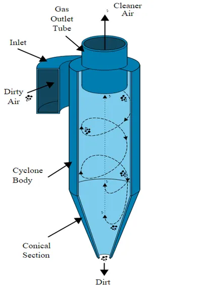
Figure:- Cyclone Separator
Cyclone separators work much like a centrifuge, but with a continuous feed of dirty air. In a cyclone separator, dirty flue gas is fed into a chamber. The inside of the chamber creates a spiral vortex, similar to a tornado. The lighter components of this gas have less inertia, so it is easier for them to be influenced by the vortex and travel up it. Contrarily, larger components of particulate matter have more inertia and are not as easily influenced by the vortex. Since these larger particles have difficulty following the high-speed spiral motion of the gas and the vortex, the particles hit the inside walls of the container and drop down into a collection hopper. These chambers are shaped like an upside-down cone to promote the collection of these particles at the bottom of the container. The cleaned flue gas escapes out the top of the chamber.
Four empirical models to calculate cyclone separator efficiency: -
1.IOZIA AND LEITH MODEL: -
Iozia and Leith's (1990) logistic model is an improved version of Barth's (1956) model which is developed based on force balance. The model assumes that a particle carried by the vortex endures the influence of two forces: a centrifugal force, Z, and flow resistance, W. Core length, zc, and core diameter, dc, are given as
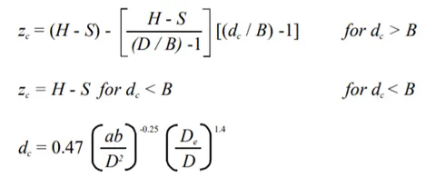
The addition made by Iozia and Leith on the original Barth (1956) model is the core length zc and slope parameter β expression which is derived based on the statistical analysis of experimental data of cyclone with D = 0.25 m. The collection efficiency ηi of particle diameter dpi can be calculated from
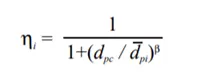
where dpc is the 50% cut size given by Barth (1956)
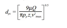
- LI AND WANG MODEL: -
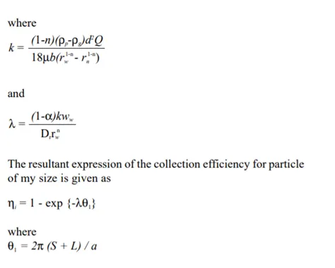
The Li and Wang (1989) model include particle bounce or re-entrainment and turbulent diffusion at the cyclone wall. A two-dimensional analytical expression of particle distribution in the cyclone is obtained. Li and Wang's model was developed based on the following assumptions:
- The radial particle velocity and the radial concentration profile are not constant, for uncollected particles within the cyclones.
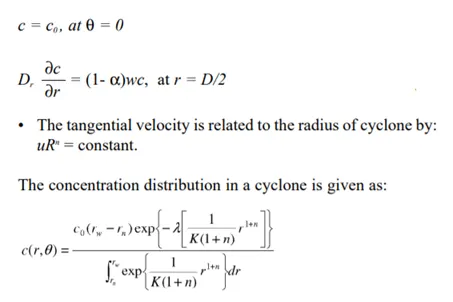
- Boundary conditions with the consideration of turbulent diffusion coefficient and particle bounce re-entrainment on the cyclone wall are:
- KOCH AND LICHT MODEL: -
Koch and Licht's (1977) collection theory recognized the inherently turbulent nature of cyclones and the distribution of gas residence times within the cyclone. Koch and Licht describe particle motion in the entry and collection regions with the additional following assumptions:
- The tangential velocity of a particle is equal to the tangential velocity of the gas flow, i.e. there is no slip in the tangential direction between the particle and the gas.
- The tangential velocity is related to the radius of the cyclone by uRn = constant. A force balance and an equation on the particles collection yields the grade efficiency ηi.
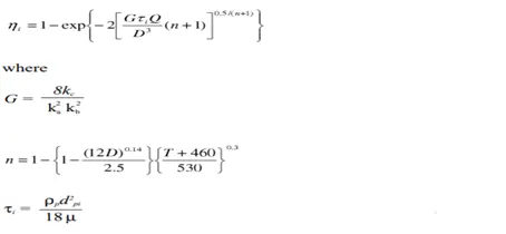
G is a factor related to the configuration of the cyclone, n is related to the vortex and τ is the relaxation term.
- LAPPLE MODEL: -
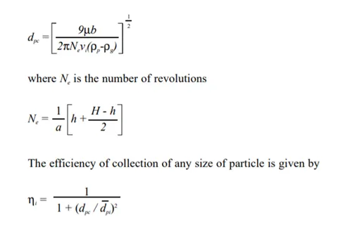
Lapple's (1951) model was developed based on force balance without considering the flow resistance. Lapple assumed that a particle entering the cyclone is evenly distributed across the inlet opening. The particle that travels from the inlet half-width to the wall in the cyclone is collected with 50% efficiency. The semi-empirical relationship developed by Lapple (1951) to calculate a 50% cut diameter, dpc, is
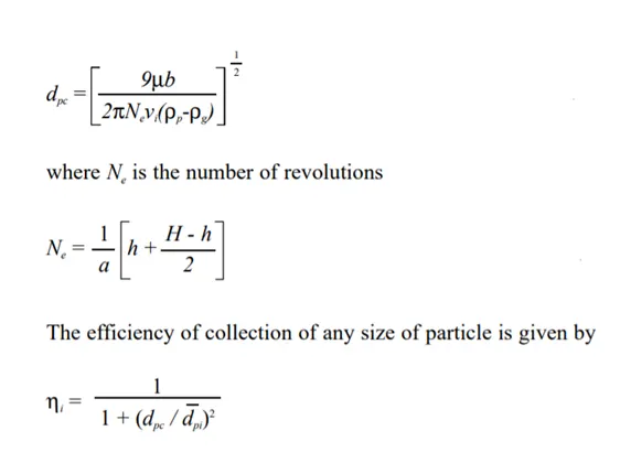
Factors that can affect a cyclone separator's efficiency are particle density, particle size, volumetric flow rate, pressure drop, cone length, body length, the ratio of accepting port to body diameter, and even the smoothness of the cyclone’s internal surfaces. We will now discuss the more important design aspects in greater detail. Particle density is one of the most deciding factors affecting a cyclone’s ability to remove entrained particles. Dense particulates such as ferrous oxides can be separated with a 99% or greater efficiency, irrespective of particle size. When the particle density decreases, the efficiency decreases (assuming no other system changes occur). Particle size is a large design consideration affecting a separator’s efficiency. Larger particles can be more easily separated than smaller particles. Particles smaller than five microns are difficult to separate without using very small separators. Particles exceeding 200 microns can often be separated using other means such as gravity-settling chambers. A reduction in particle size will give a corresponding reduction in efficiency.
Analysis and Results:-
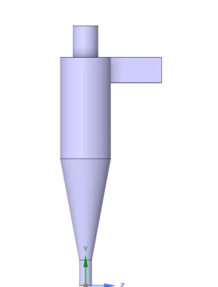
Extracted Fluid Volume:-
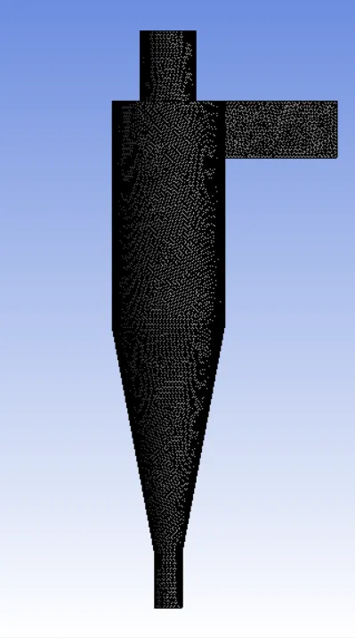
Mesh Generated: -
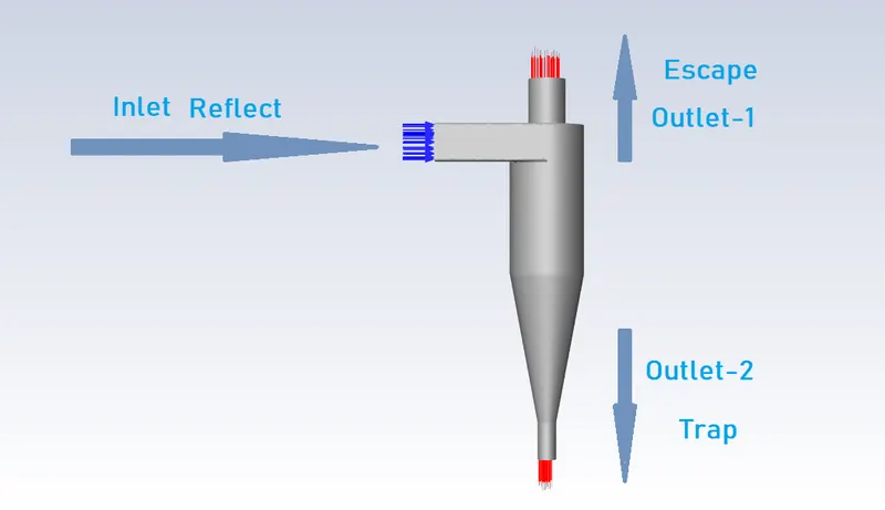
Boundary Conditions: -
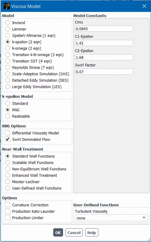
Viscous Model: -
Results: -
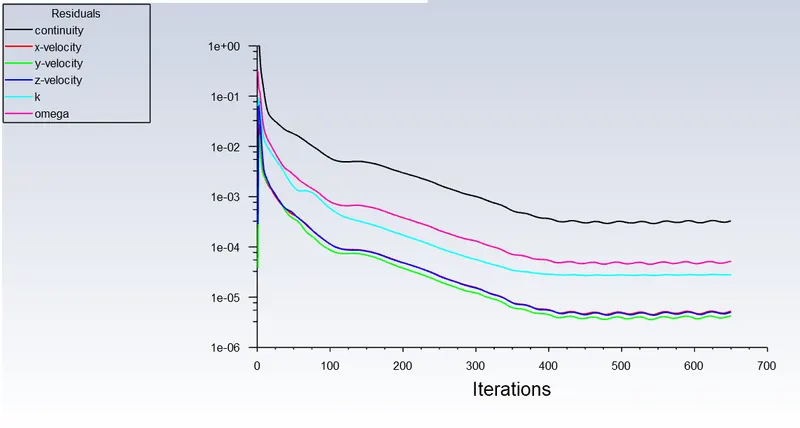
Residuals: -
Part-A: - Variable Sizes ( 1e-06 to 5e-06)
Particle inlet velocity and inlet velocity = 3m/s
1. Size - 1e-06
Particle time:-
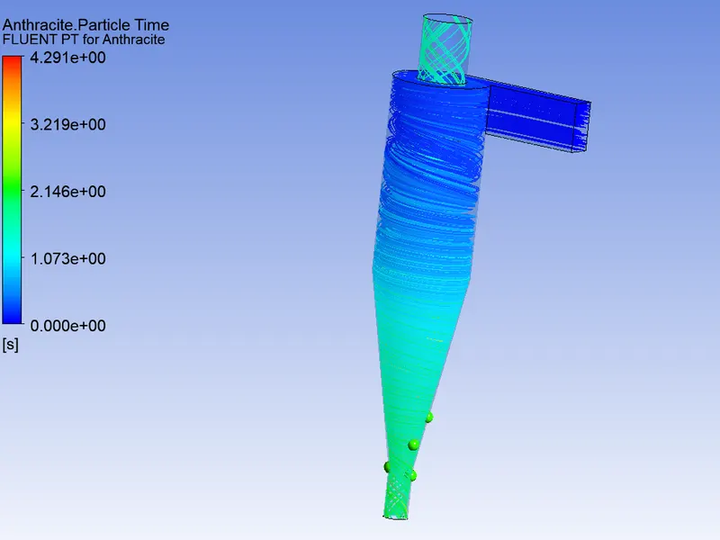
Particle Tracking:-

2. Size - 2e-06
Particle time:-
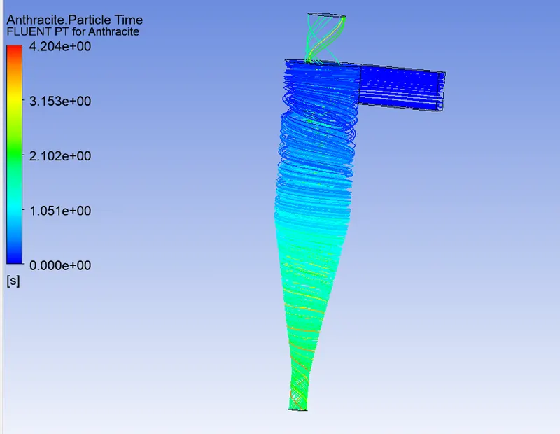
Particle Tracking:-
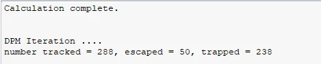
3. Size - 3e-06
Particle time:-
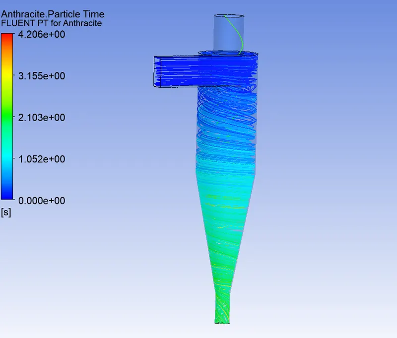
Particle Tracking:-
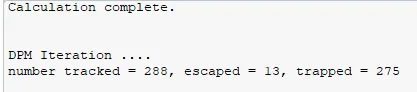
4. Size - 4e-06
Particle time:-
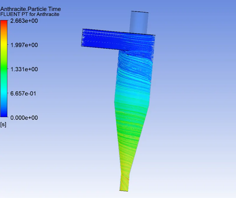
Particle Tracking:-
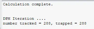
5. Size - 5e-06
Particle time:-
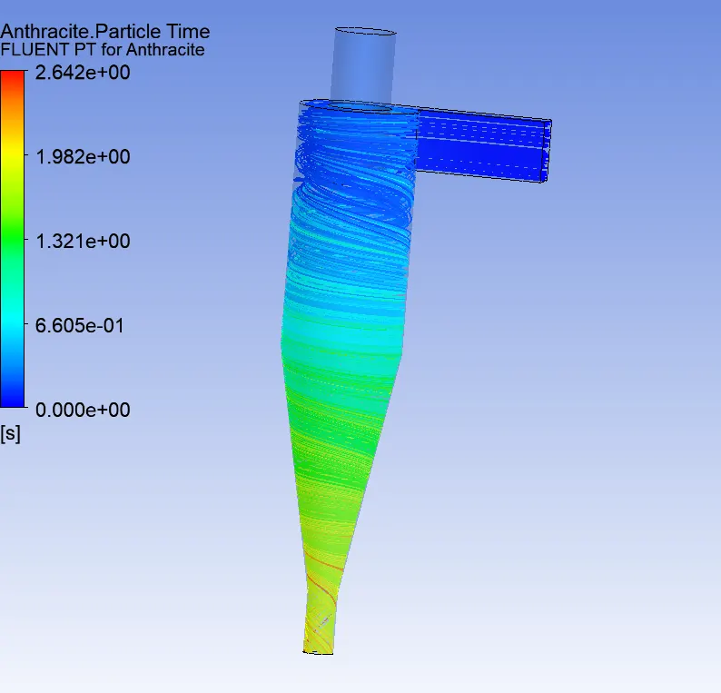
Particle Tracking:-
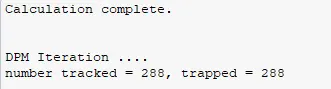
Separation Efficiency for Different Sizes:-
| Sr.No | Particle Size (m) | Particles Tracked | Trapped | Escaped | Efficiency (%) |
| 1 | 1e-06 | 288 | 220 | 60 | 76.39 |
| 2 | 2e-06 | 288 | 238 | 50 | 82.64 |
| 3 | 3e-06 | 288 | 275 | 13 | 95.48 |
| 4 | 4e-06 | 288 | 288 | 0 | 100 |
| 5 | 5e-06 | 288 | 288 | 0 | 100 |
Part-B: - Variable Velocity ( 1 m/s to 5 m/s)
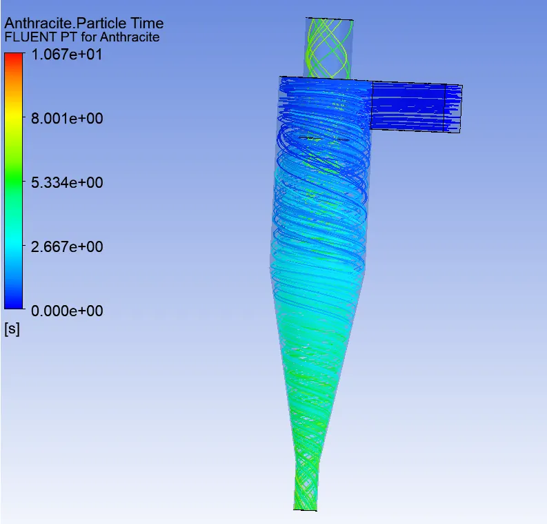
1.Velocity= 1m/s
Particle inlet velocity and inlet velocity = 1 m/s
Particle time:-
Velocity:-
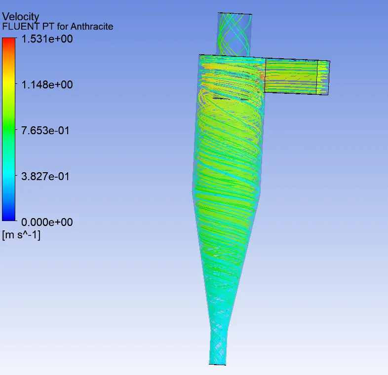
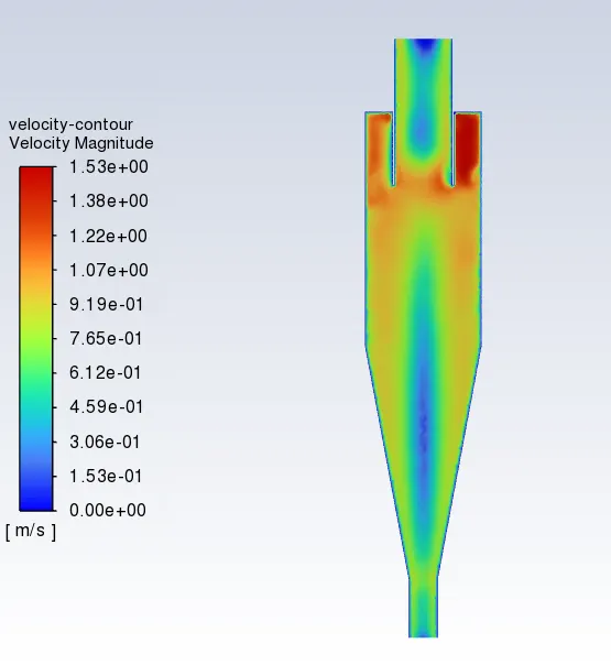
Pressure contour:-
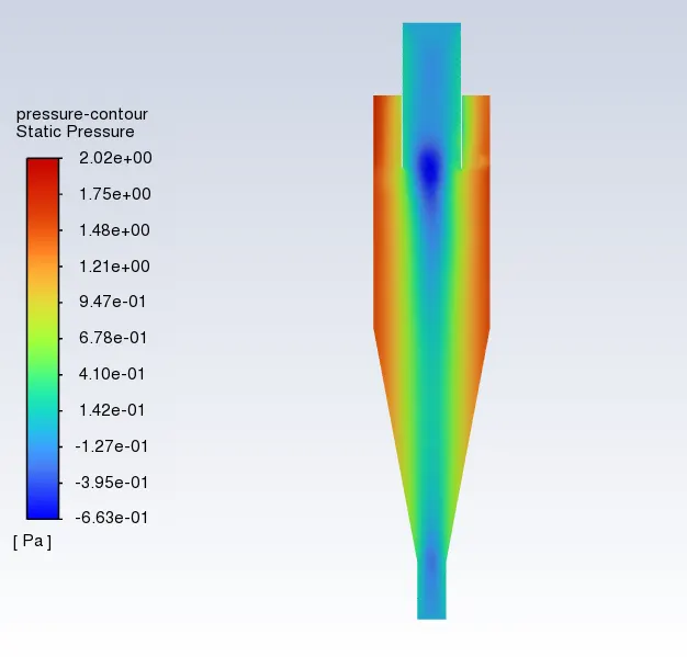
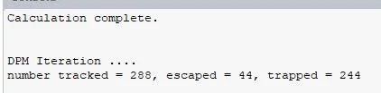
Particle Tracking:-
2.Velocity= 2m/s
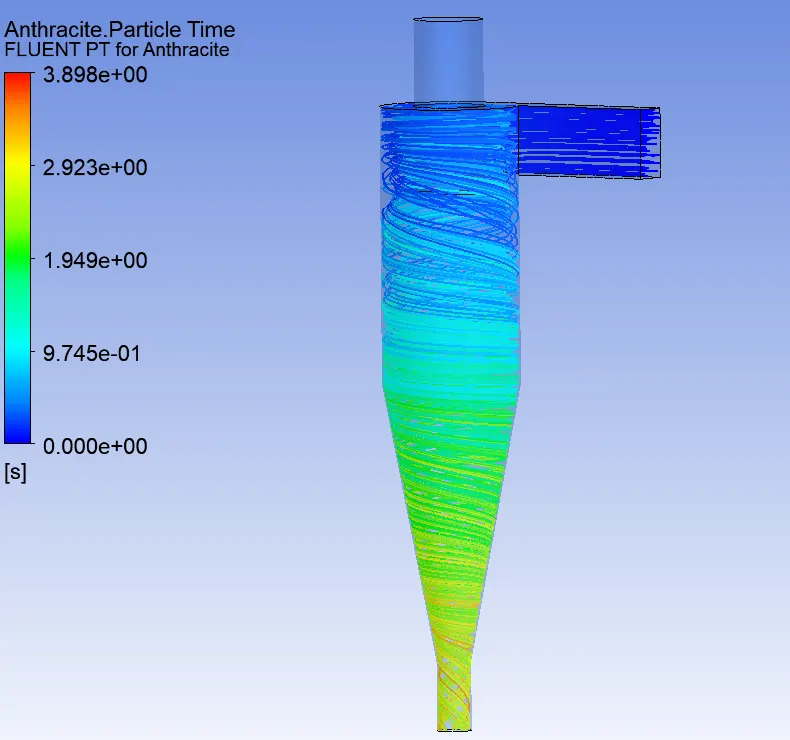
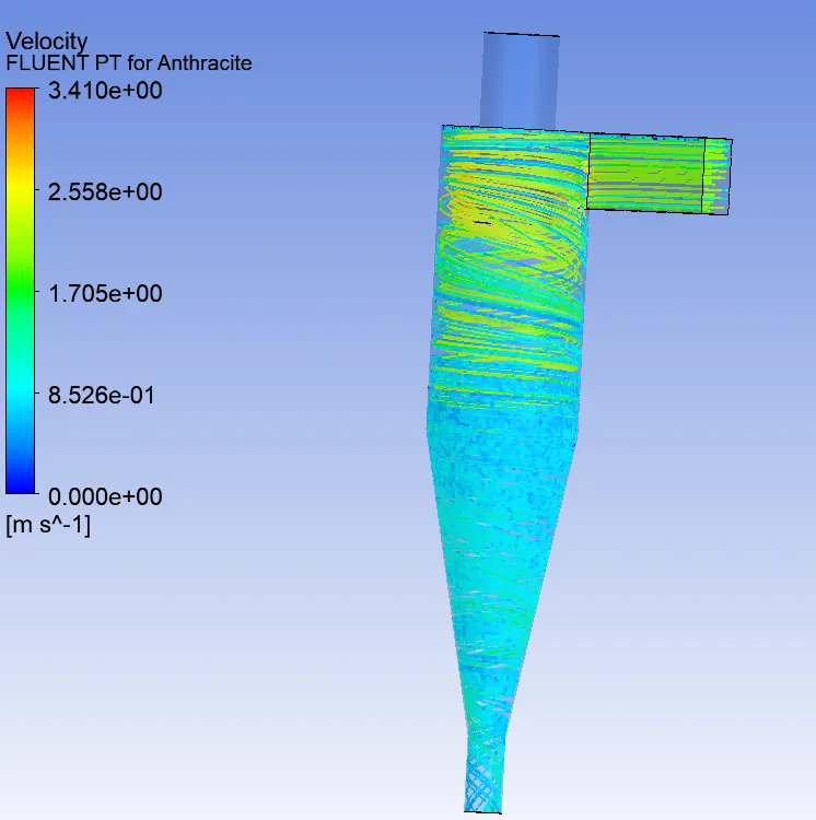
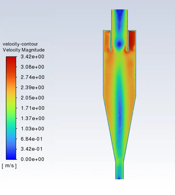
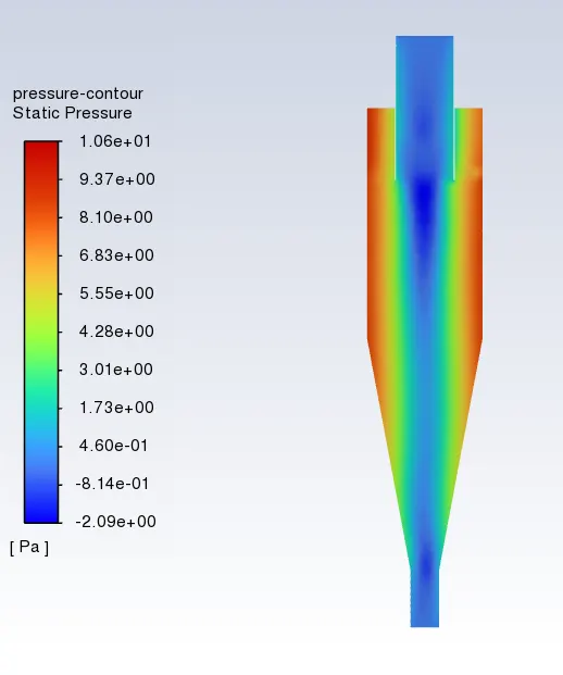
Particle inlet velocity and inlet velocity = 2 m/s
Particle time:-
Velocity:-
Pressure contour:-
Particle Tracking:-
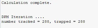
3.Velocity= 3 m/s
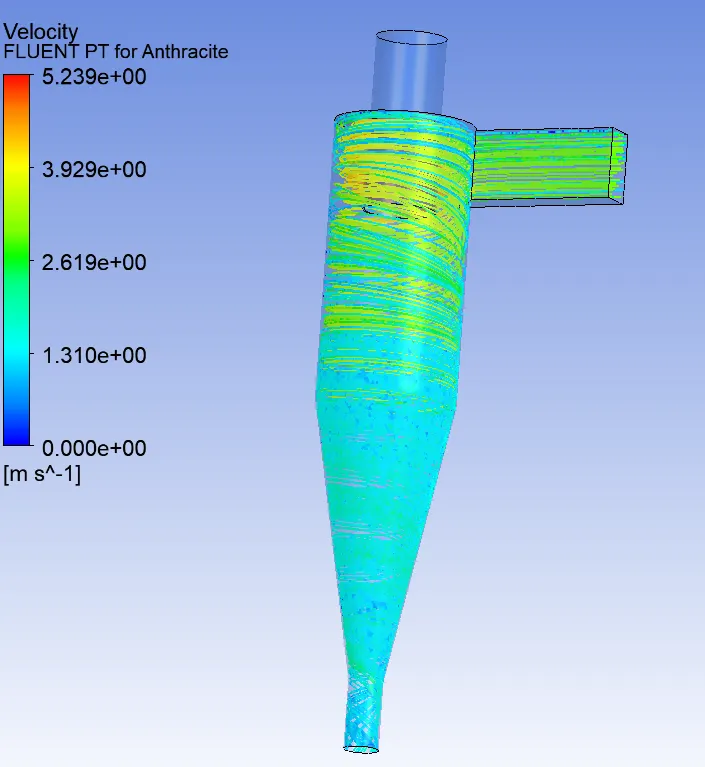
Particle inlet velocity and inlet velocity = 3 m/s
Particle time:-
Velocity:-
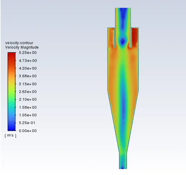
Pressure contour:-
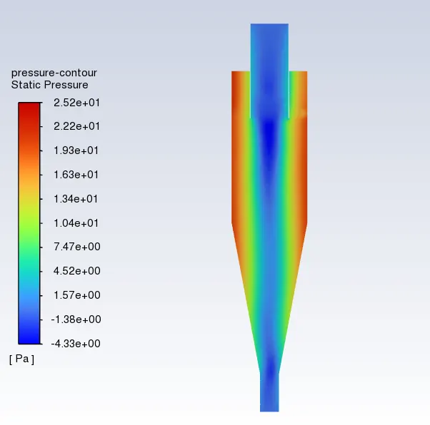
Particle Tracking:-
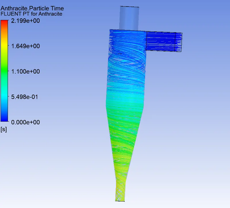
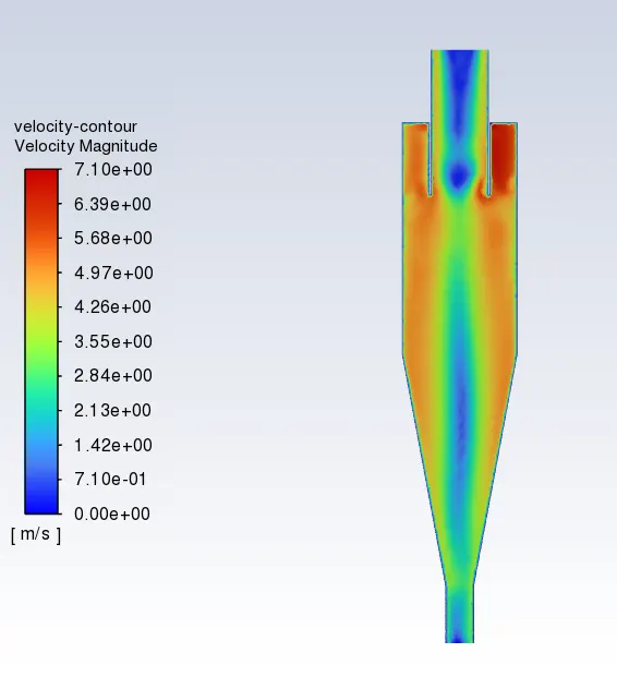
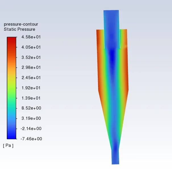
4.Velocity= 4 m/s
Particle inlet velocity and inlet velocity = 4 m/s
Particle time:-
Velocity:-
Pressure contour:-
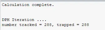
Particle Tracking:-
5.Velocity= 5m/s
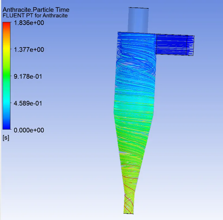
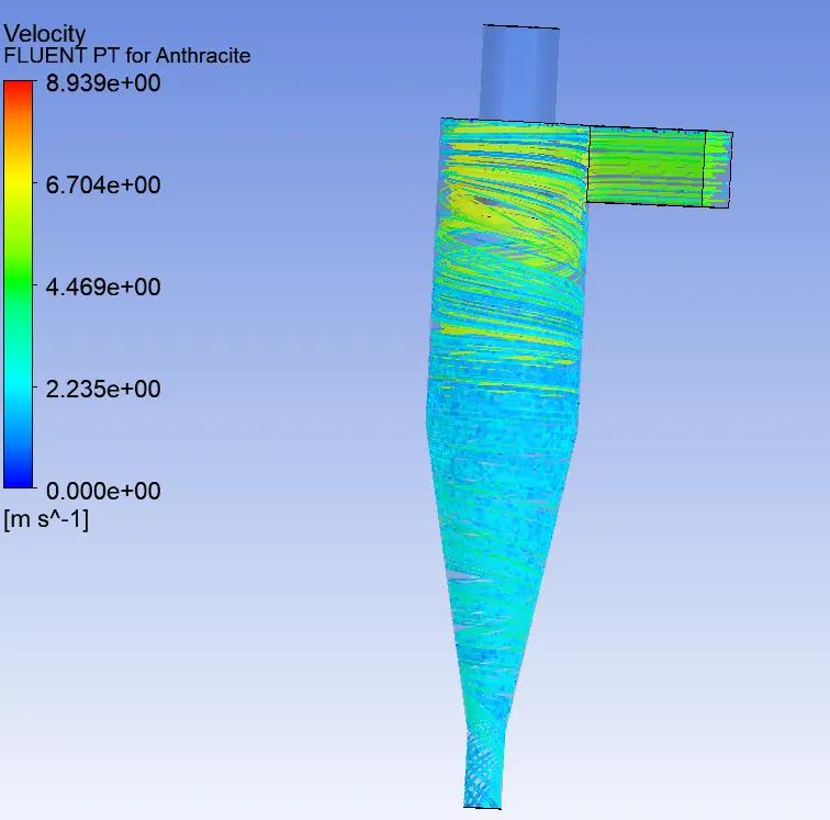
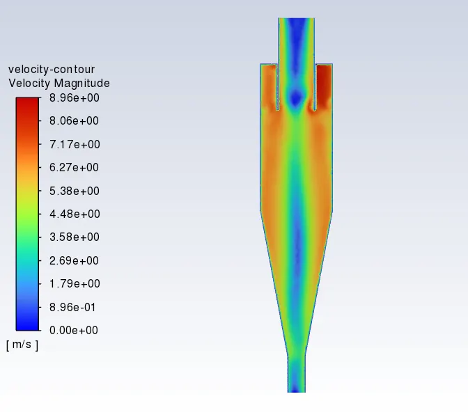
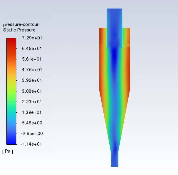
Particle inlet velocity and inlet velocity = 5 m/s
Particle time:-
Velocity:-
Pressure contour:-
Particle Tracking:-
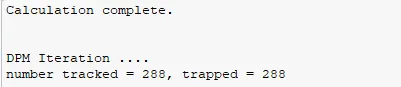
Separation Efficiency for Different Velocities:-
| Sr.No | Particle Velocity | Particles Tracked | Trapped | Escaped | Efficiency (%) |
| 1 | 1 m/s | 288 | 244 | 44 | 84.73 |
| 2 | 2 m/s | 288 | 288 | 0 | 100 |
| 3 | 3 m/s | 288 | 288 | 0 | 100 |
| 4 | 4 m/s | 288 | 288 | 0 | 100 |
| 5 | 5 m/s | 288 | 288 | 0 | 100 |
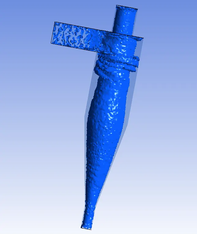
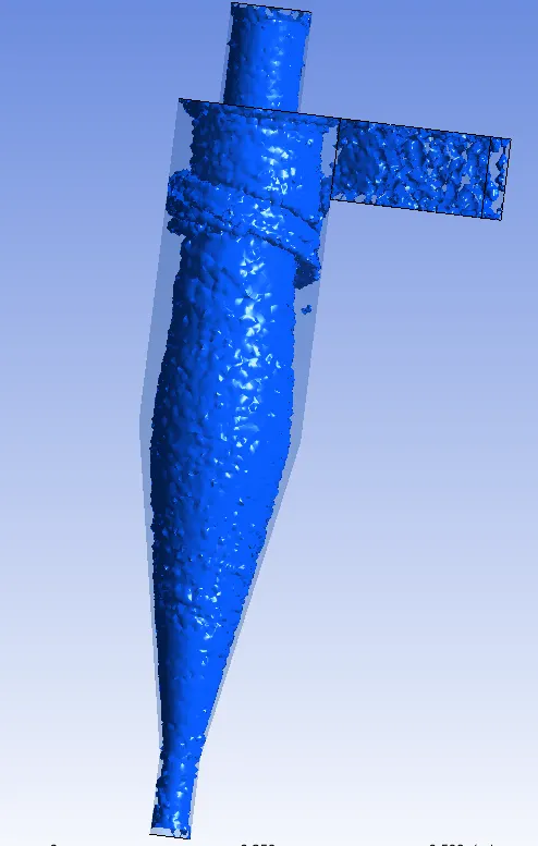
Vortex Region: -
Cyclone Separator Animation: -
Conclusion:-
1. Separation efficiency increase with the increase in the diameter of the particle.
2. Separation efficiency increase with the increase in velocity.
3. Larger particle sizes have higher efficiency, although inlet velocity is low compared to lower size particles.
3. Pressure drop is almost identical with constant velocity, although particle size changes.